ACCC conductor overview
•
2 likes•2,085 views

Overview of the high-capacity, low-sag ACCC conductor used to improve the efficiency, capacity, reliability and resiliency of the electric power transmission grid

Recommended
Recommended
More Related Content
What's hot
What's hot (20)
Similar to ACCC conductor overview
Similar to ACCC conductor overview (20)
More from Dave Bryant
More from Dave Bryant (11)
Recently uploaded
Recently uploaded (20)
ACCC conductor overview
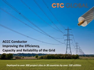
- 1. ACCC Conductor Improving the Efficiency, Capacity and Reliability of the Grid Deployed to over 300 project sites in 30 countries by over 100 utilities
- 2. 1900 2000 Lets take a quick look back… What has changed? Generation, Transmission and Demand-Side Appliances saw improvements, but the fundamentals remained basically the same
- 3. Until Now… 2010 +++ Why… Because Efficiency, Capacity and Reliability Offer Substantial Social & Economic Benefits Globally, we have invested billions of dollars improving the efficiency of generation and demand-side appliances. Now we are investing billions more gathering data about generation capacity & consumer habits. Some call this “Smart Grid.” What about the grid itself?
- 4. A true “Smart Grid” needs to be Efficient, Reliable & Robust In August 2003, the US/Canada blackout was caused by a number of factors: • This included incorrect telemetry data, a “race condition” computer bug in an Energy Management System and three 345kV transmission line trips due to excessive conductor sag. This led to cascading sag-trip outages on the 138kV distribution system. • These events and lack of effective communication between utilities ultimately shut down 508 generation units at 265 power plants. • The use of a high-capacity, low-sag conductor such as ACCC® could have prevented the cascading outages, in spite of the computer & telemetry glitches It takes more than computers & telemetry to build a “Smart Grid” ACCC® ACSR
- 5. Why is this so important? Because, without Reliable & Affordable Electricity… • We can’t pump water to grow crops • We can’t develop the infrastructure to attract new business • We can’t improve the quality of life for millions of people …and build stable, peaceful, and productive economies
- 6. ACCC (Aluminum Conductor Composite Core) Its hybrid carbon fiber core is 70% lighter and 50% stronger than steel. Its has a coefficient-of-thermal-expansion about 10 times less than steel. This allows the use of 28% more aluminum which helps increase capacity, improve efficiency & mitigate thermal sag. High Performance Conductor for a Modern Grid
- 7. Greater Strength & Reduced Sag Higher Ampacity Limits at Cooler Temperatures Able to Tolerate N-1 Conditions Increased Spans on Fewer / Shorter Structures Proven Reliability with Reduced Line Losses Selected as the Most Cost Effective Solution High-Capacity, Low-Sag ACCC Offers: ACCC has been installed by over 100 utilities at over 300 project sites. 10 years of Installation & Operating Experience
- 8. Carbon Fiber Widely Utilized High Strength, Light Weight & Excellent Resistance to Cyclic Load Fatigue
- 9. ACSS ACCC After Sheave Test, 100 Million Cycles of Vibration, 100 Thousand Cycles of Galloping, and Tensile Test Testing performed by American Electric Power (AEP) proved the ACCC conductor’s superior resistance to vibration and cyclic load fatigue. ACCC is Resistant to Cyclic Load Fatigue
- 10. 0 10 20 30 40 50 60 70 80 0 20 40 60 80 100 120 140 160 180 200 220 240 260 CableSag(Inches) Temperature (C) ACCC GAP Invar ACCR ACSS ACSR How Does it Compare to Other Conductors? Comparison testing performed by Hydro One on a 65 meter span, 1600 amps, Drake size Cooler operating temperatures underscore improved efficiency and reduced losses
- 11. 1. Developed & Tested the Composite Core 2. Tested Electrical Properties of the Conductor 3. Developed & Tested Ancillary Hardware 4. Assessed Environmental Exposure and Longevity 5. Evaluated Conventional Installation Procedures 6. Commercially Deployed in 2005 7. ISO Certified in 2006 The Substantial Path to ACCC® Deployment In consultation with several International Utilities and laboratories, CTC Global:
- 12. Core Testing: 2.1.1 Tensile Testing 2.1.2 Flexural, Bending & Shear Tests 2.1.3 Sustained Load Tests 2.1.4 Tg Tests 2.1.5 CTE Measurements 2.1.6 Shear Testing 2.1.7 Impact and Crush Testing 2.1.8 Torsion Testing 2.1.9 Notched Degradation Testing 2.1.10 Moisture Resistance Testing 2.1.11 Long Term Thermal Testing 2.1.12 Sustained Load Thermal Testing 2.1.13 Cyclic Thermal Testing 2.1.14 Specific Heat Capacity Testing 2.1.15 High Temperature Short Duration 2.1.16 High Temperature Core Testing 2.1.17 Thermal Oxidation Testing 2.1.18 Brittle Fracture Testing 2.1.19 UV Testing 2.1.20 Salt Fog Exposure Tests 2.1.21 Creep Tests 2.1.22 Stress Strain Testing 2.1.24 Micrographic Analysis 2.1.25 Dye Penetrant Testing 2.1.26 High Temperature Shear Testing 2.1.27 Low Temperature Shear Testing Mechanical Conductor Testing: 2.2.28 Stress Strain Testing 2.2.29 Creep Testing 2.2.30 Aeolian Vibration Testing 2.2.31 Galloping Tests 2.2.32 Self Damping Tests 2.2.33 Radial Impact and Crush Tests 2.2.34 Turning Angle Tests 2.2.35 Torsion Tests 2.2.36 High Temperature Sag Tests 2.2.37 High Temperature Sustained Load 2.2.38 High Temperature Cyclic Load Tests 2.2.39 Cyclic Ice Load Tests 2.2.40 Sheave Wheel Tests 2.2.41 Ultimate Strength Tests 2.2.42 Cyclic Thermo-Mechanical Testing 2.2.43 Combined Cyclic Load Testing 2.2.44 Conductor Comparison Testing Electrical Conductor Testing: 2.3.45 Resistivity Testing 2.3.46 Power Loss Comparison Testing 2.3.47 Ampacity 2.3.48 EMF Measurements 2.3.49 Impedance Comparison Testing 2.3.50 Corona Testing 2.3.51 Radio Noise Testing 2.3.52 Short Circuit Testing 2.3.53 Lightning Strike Testing 2.3.54 Ultra High Voltage AC & DC Testing Systems & Hardware Testing: 2.4.55 Current Cycle Testing 2.4.56 Sustained Load Testing 2.4.57 Ultimate Assembly Strength Testing 2.4.58 Salt Fog Emersion Testing 2.4.60 Static Heat Tests 2.4.61 Suspension Clamp Testing 2.4.62 Thermo-Mechanical Testing 2.4.63 Cyclic Load Testing Field Testing: 2.5.64 Ambient Temperature 2.5.65 Tension, Sag, and Clearance 2.5.66 Conductor Temperature 2.5.67 Electric Current 2.5.68 Wind Speed and Direction 2.5.69 Solar Radiation 2.5.70 Rainfall 2.5.71 Ice Buildup 2.5.72 Splice Resistance 2.5.73 Infrared Measurements 2.5.74 Corona Observations 2.5.75 Electric and Magnetic Fields 2.5.76 Wind and Ice Load Measurements 2.5.77 Vibration Monitoring 2.5.78 Typhoon Test US / UK / France / Canada / Mexico / China / Brazil / Chile / Belgium / Indonesia / Germany Testing & Validation
- 13. Torsion Testing “After completing nearly one and a half revolutions per foot, my lab guys got tired of trying to break it so they gave up.” Craig Pon, Kinectrics 4 Revolutions 54 Revolutions
- 14. Bending Tests Conductor bent 90 degrees 10 times around a 6 inch radius. No visual damage to core was noted. Dye penetrant did appear after 2 minutes in the outer glass strands showing some degradation.
- 15. Thermal Oxidation Tests Core sample cooked at 220OC for one year Oxidation limited to ~60 microns in depth
- 16. Longevity Assessment by Alpha Star Primary Contractor to Boeing, Airbus and NASA Substantial Empirical Test Data provided the basis for high-level & very accurate computer modeling
- 17. Substantial Experience 25,000 km at ~300 project sites Over 35,000 Dead-Ends & Splices in service Countries: • USA • China • France • UK • Poland • Spain • Portugal • Mexico • Chile • Qatar • Indonesia • Belgium • Brazil • Germany • South Africa • South Korea • Russia • India • Costa Rica • Columbia • Congo • Mozambique • Netherlands • Nigeria • Vietnam US Utilities: • AEP • APS • PacifiCorp • NV Energy • Austin Energy • Xcel Energy • MI PUD • KS PUD • KAMO • OG&E • Ozark Electric • WAPA • STEC • Entergy • Riverside PUD • Florida Power & Light • Keys Energy • Progress Energy • Mohave Electric • SCANA • National Grid • Alexandria (LA) PUD • Duke Energy • Oncor • CIPCO • Black Hills Power • Com Ed • TECO
- 18. Utah, USA Reconductor Project Project Name: PacifiCorp 90 South to Oquirrh, Utah Project Goal: Increase Ampacity (use existing structures) Conductor Size: Drake Conductor Length: 30 km Voltage: 138 kV Energized: 2005 Over 100 existing structures saved
- 19. Kansas, USA New Line Project Name: Kingman to Cunningham, Kansas Project Goal: Install New Line Conductor Size: Hawk Conductor Length: 108 km Voltage: 34.5 kV Energized: 2006
- 20. Nevada, USA Heavy Ice Application Project Name: NV Energy Line 107 (Reno to Carson City) Project Goal: Increase Ampacity (existing structures) Conductor Size: Linnet Conductor Length: 90 km Voltage: 120 kV Energized: 2009
- 21. Mexico Bay Corrosive Marine Environment Project Name: CFE Carmen to Noreste Goal: Increase ampacity reduce line sag, avoid corrosion Conductor Size: Hawk Conductor Length: 32 km Voltage: 230 kV Energized: 2009
- 22. Chile Long Span Application Project Name: Chilectra El Salto to Torre 8 Line Project Goal: Increase Ampacity – (existing structures) Conductor Size: Linnet Conductor Length: 28 km Voltage: 110 kV Energized: 2009
- 23. Spain Wind Farm Link Project Name: NEO Energia 80 turbine upgrade Project Goal / Type: Increase Ampacity (existing structures) Conductor Size: Amsterdam Conductor Length: 57 km Voltage: 66 kV Energized: 2008
- 24. Germany Extra High Voltage Application Project Name: Amprion Gmbh Project Goal / Type: Trial Line Conductor Size: Oslo (bundled) Length: 8.6 km Voltage: 400 kV Energized: 2009
- 25. Nevada, USA Extreme Wind Survival Project Name: NV Energy Line 107 (Reno to Carson City) Project Goal: Increase Ampacity (existing structures) Conductor Size: Linnet Conductor Length: 90 km Voltage: 120 kV Energized: 2009 100+ mph Winds: 2010 Conductor Undamaged
- 26. Nevada, USA Fire Storm Survival Project Name: NV Energy Line 107 (Reno to Carson City) Project Goal: Increase Ampacity (existing structures) Conductor Size: Linnet Conductor Length: 90 km Voltage: 120 kV Energized: 2009 Firestorm: 2012 – ACCC CONDUCTOR UNDAMAGED
- 27. Portugal River Crossing Project Name: River Mondego Project Goal: Increase Amps - Reduce Sag Conductor Size: Amsterdam Span Length: 475 Meters Voltage: 60 kV Energized: 2012
- 28. Fujian Provence, China Typhoon Survival (2,600’ spans)ED
- 30. UK France California Kansas Ice & Wind Load Testing
- 31. Lessons Learned
- 32. 1. Pulling sleeve “sock” swivels broke causing conductor to drop (US, Poland, Columbia) Inspect/test older equipment prior to use 2. Installation grips slipped causing birdcage (Vietnam, US, Russia) Use correct size grip 3. Conductor damaged at dead-end interface (US, China) Do not kick dead-end out of compression die, use soap to lubricate dies 4. Conductor damaged at installation grip (Indonesia) Control loose end while installing dead-end, don’t drop assembly which could cause excessive bending at Chicago grip 5. Core damaged while being bent around very small reel alignment pulleys (US, Poland) Use hydraulic reel brakes to control back tension Use mid-span sheave wheel to avoid sharp bending when necessary Installation Events & Corrective Actions
- 36. Installation Training and Support Check out our installation Training Videos on YouTube
- 37. A few of CTC’s International Customers:
- 38. Why Did These Utilities Choose ACCC? Because, after discovering its technical merits and evaluating its durability, it provided the most economical solution for their specific projects
- 39. The Value of Line Loss Reduction Reduced line losses saves money… every year
- 40. The Value of Generation Capacity Savings Reduced line losses reduces generation capacity investment It is much less expensive to save energy than it is to produce it
- 41. The Value of Emission Reduction Reduced line losses reduces fuel consumption …and associated emissions
- 42. • Over 40 standard conductor sizes • New ULS conductors for extreme spans • Design & Engineering Support • 24/7 Customer Service • Installation Training & Support • Extensive Engineering Database GLOBAL Support
- 43. ACCC Engineering Manual: Helpful resource for understanding the unique attributes of ACCC Conductor
- 45. Stay Informed with our Monthly Newsletters:
- 46. • Privately held Delaware Corporation • Headquartered in Irvine, California • R&D began in 2003 • Trial Lines Installed in 2004 • Commercially Deployed in 2005 • ISO Certified Production in 2006 • Stranding Partners Worldwide • Over 25,000 km at over 300 project sites CTC Global Corporation
- 48. Low Thermal Sag and High Strength Allow: Increased capacity, increased revenue & reduced congestion Fewer short-circuit events & improved reliability Increased spans between fewer and/or shorter structures Added Aluminum Content (without any weight penalty) Allow: A 25 to 40% reduction in line losses (depending upon load) Reduced fuel consumption & reduced emissions Reduces generation capacity requirements Additional Advantages: Higher strength core reduces risk of mechanical failure Composite core is impervious to corrosion Composite core resists cyclic load fatigue Summary of Technical Advantages:
- 49. ACCC® Conductor Improving the Efficiency, Capacity, Reliability & Resilience of the Grid CTC Global 2026 McGaw Avenue Irvine, California 92614 USA +1 (949) 428-8500 www.ctcglobal.com