1) Wireless power transfer uses inductive coupling between transmitter and receiver coils to transfer electrical energy without interconnects. It was first studied by Nikola Tesla in the late 1800s.
2) Magnetic induction is commonly used for wireless power transfer but efficiency decays with distance due to reduced mutual inductance between coils. Resonant coupling tunes both coils to the same frequency to improve efficiency.
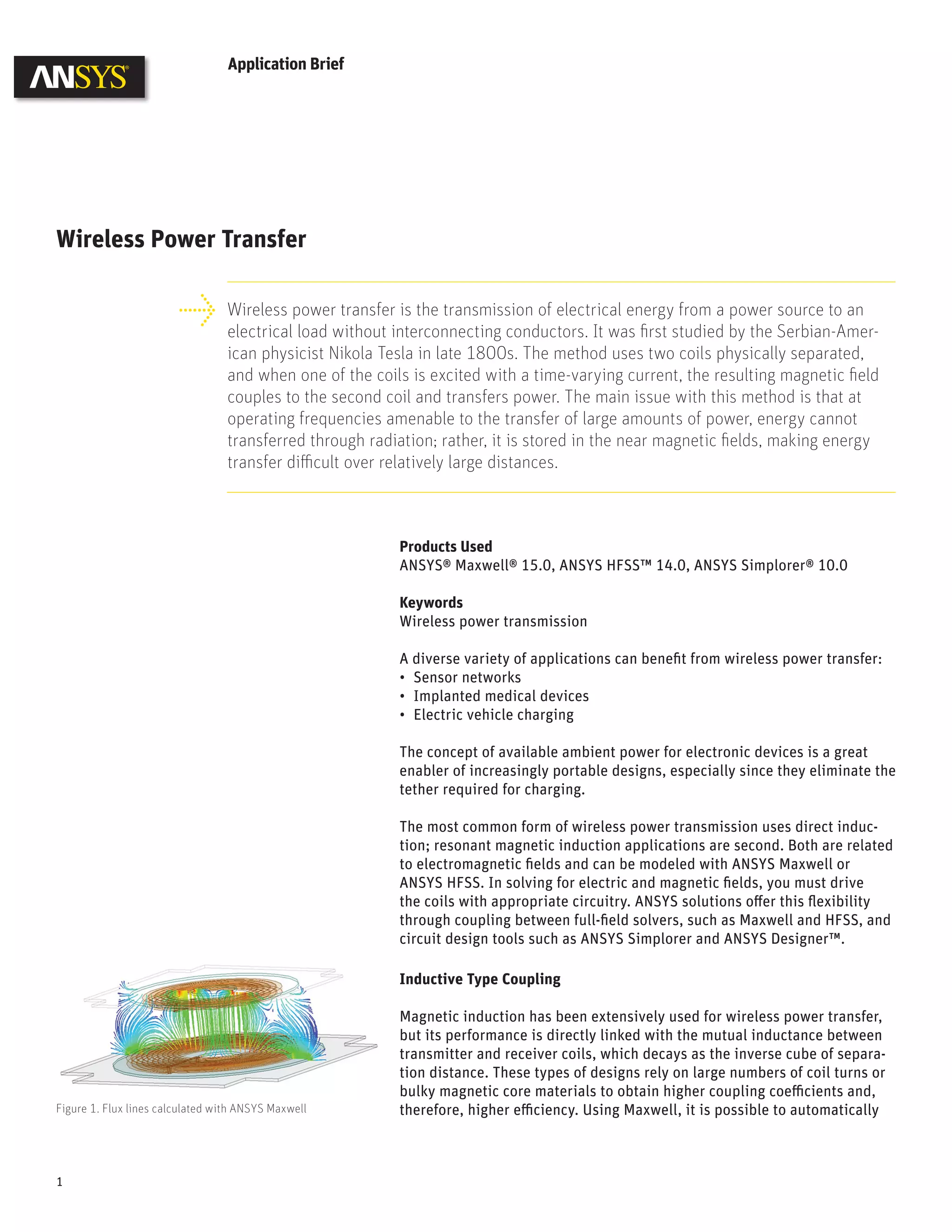
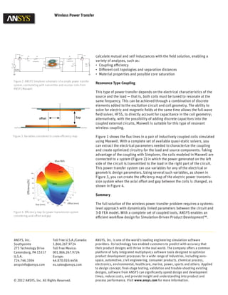
3) ANSYS software such as Maxwell and HFSS can model electromagnetic fields and calculate coil parameters to optimize wireless power transfer designs through circuit coupling and efficiency mapping of parameters like coil offset and gap.