The document discusses a novel method for maximum power point tracking (MPPT) in solar photovoltaic (PV) water pumping systems to enhance power output by focusing on maximizing load voltage. This new approach, termed maximum load voltage point tracking (MVPT), simplifies the process by requiring only load voltage monitoring rather than the more complex PV panel power monitoring. The theoretical findings are supported by MATLAB-Simulink simulations, demonstrating that the method results in improved power harnessing even at varying radiation levels.
![Full Paper
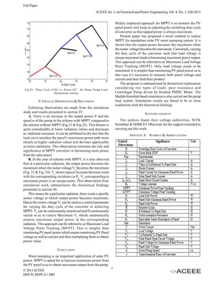
ACEEE Int. J. on Electrical and Power Engineering, Vol. 4, No. 1, Feb 2013
Solar Photo Voltaic Water Pumping: Harnessing
Maximum Power
Mrityunjaya Kappali 1*, Dr. Uday Kumar R. Y.2 and V. R. Sheelavant 3
1*
& 3 :Faculty, Electrical & Electronics Engineering,
SDM College of Engg. & Tech., Dharawd -580002, India.
Email: mrkappali@rediffmail.com
2
Professor, Electrical & Electronics Engineering,
National Institute of Technology Karnataka, Surathkal,
Mangalore -575025, India.
Abstract- Among alternate sources of electricity, Solar Photo
Voltaic (PV) energy is gaining prominence due to its plentiful
availability. Water pumping is an important application of
solar PV power. However people are not opting for it in large
numbers as the ‘cost per watt’ for solar pumping systems is
high. The cost can be reduced by harnessing more power per
unit installed capacity of the solar panel. One method of
realising this is by Maximum Power Point Tracking (MPPT)
wherein a power electronic converter is used to match pump
with the PV panel. Widely employed approach for MPPT is to
monitor the PV panel power and keep on adjusting the duty
cycle of converter so that tapped power is always maximum.
Present paper proposes a novel method to realise MPPT for Fig.1. Typical “Vp vs. Ip” for PV Panel
standalone solar PV water pumping system. It is shown that
the output power becomes the maximum when the motor
voltage becomes the maximum. Conversely, varying the duty
cycle of the converter such that load voltage is always maximum
leads to harnessing maximum power output. This approach
can be referred to as Maximum Load Voltage Point Tracking
(MVPT). We need to monitor only load voltage. It is simpler
than monitoring PV panel power as in that case it’s necessary
to measure both panel voltage and current and then find their
product.
The proposal of MVPT for realizing MPPT is substantiated
by theoretical explanation considering two types of loads: Pure
Resistance and Centrifugal Pump driven by Permanent Magnet
(PM ) brushed DC Motor. The Matlab-Simulink based Fig.2. Typical ‘Vp vs. Pp ’ for PV Panel
simulation is also carried out. Simulation results are found put power of the panel becomes the maximum. The process
to be in close conformity with the theoretical findings. of controlling the operating point of solar PV panel so that it
Index Terms: Maximum Power Harnessing; Water Pumping; always corresponds to maximum power at the corresponding
Solar Photo Voltaic; Brushed DC Motor Pump. radiation is referred to as Maximum Power Point Tracking
(MPPT). This needs matching between the load and PV panel
I. INTRODUCTION and can be accomplished by connecting a power electronic
converter with variable switching duty cycle (D) as the inter-
People are not opting for solar PV based Water pumping phase between the PV panel and the load [4]. There exist
in big nunber as the “cost per watt” of these systems is high. different strategies to vary D [5] which can be broadly cat-
Around the world only 60000 solar pumping systems are egorized as:
installed [1]. This number is just 5000 in India [2]. The cost
A. Interruptive Type
can be reduced by harnessing more power per unit installed
capacity of the solar panel. This has mainly two approaches. The first one is to
Solar PV panel exhibits [3] typical “Voltage vs. Current” maintain Vp at a value which is a fixed percentage of open
(Vp-Ip) (Fig.1) and “Voltage vs. Power” (Vp-Pp) (Fig.2) charac- circuit voltage (Voc). This requires monitoring of Voc. Another
teristics as a function of solar radiation. At each radiation, approach is to maintain the panel current (Ip) as a fixed
represented proportionally by the panel short circuit current percentage of short circuit current (I sc ). This requires
Iph, there exists a particular operating point at which the out- monitoring of Isc. These two approaches, though simple,
require regular delinking (interruption) of panel from the load
1* Corresponding author.
© 2013 ACEEE 1
DOI: 01.IJEPE.4.1.1062](https://image.slidesharecdn.com/1062-130304012626-phpapp01/85/Solar-Photo-Voltaic-Water-Pumping-Harnessing-Maximum-Power-1-320.jpg)
![Full Paper
ACEEE Int. J. on Electrical and Power Engineering, Vol. 4, No. 1, Feb 2013
Solar Photo Voltaic Water Pumping: Harnessing
Maximum Power
Mrityunjaya Kappali 1*, Dr. Uday Kumar R. Y.2 and V. R. Sheelavant 3
1*
& 3 :Faculty, Electrical & Electronics Engineering,
SDM College of Engg. & Tech., Dharawd -580002, India.
Email: mrkappali@rediffmail.com
2
Professor, Electrical & Electronics Engineering,
National Institute of Technology Karnataka, Surathkal,
Mangalore -575025, India.
Abstract- Among alternate sources of electricity, Solar Photo
Voltaic (PV) energy is gaining prominence due to its plentiful
availability. Water pumping is an important application of
solar PV power. However people are not opting for it in large
numbers as the ‘cost per watt’ for solar pumping systems is
high. The cost can be reduced by harnessing more power per
unit installed capacity of the solar panel. One method of
realising this is by Maximum Power Point Tracking (MPPT)
wherein a power electronic converter is used to match pump
with the PV panel. Widely employed approach for MPPT is to
monitor the PV panel power and keep on adjusting the duty
cycle of converter so that tapped power is always maximum.
Present paper proposes a novel method to realise MPPT for Fig.1. Typical “Vp vs. Ip” for PV Panel
standalone solar PV water pumping system. It is shown that
the output power becomes the maximum when the motor
voltage becomes the maximum. Conversely, varying the duty
cycle of the converter such that load voltage is always maximum
leads to harnessing maximum power output. This approach
can be referred to as Maximum Load Voltage Point Tracking
(MVPT). We need to monitor only load voltage. It is simpler
than monitoring PV panel power as in that case it’s necessary
to measure both panel voltage and current and then find their
product.
The proposal of MVPT for realizing MPPT is substantiated
by theoretical explanation considering two types of loads: Pure
Resistance and Centrifugal Pump driven by Permanent Magnet
(PM ) brushed DC Motor. The Matlab-Simulink based Fig.2. Typical ‘Vp vs. Pp ’ for PV Panel
simulation is also carried out. Simulation results are found put power of the panel becomes the maximum. The process
to be in close conformity with the theoretical findings. of controlling the operating point of solar PV panel so that it
Index Terms: Maximum Power Harnessing; Water Pumping; always corresponds to maximum power at the corresponding
Solar Photo Voltaic; Brushed DC Motor Pump. radiation is referred to as Maximum Power Point Tracking
(MPPT). This needs matching between the load and PV panel
I. INTRODUCTION and can be accomplished by connecting a power electronic
converter with variable switching duty cycle (D) as the inter-
People are not opting for solar PV based Water pumping phase between the PV panel and the load [4]. There exist
in big nunber as the “cost per watt” of these systems is high. different strategies to vary D [5] which can be broadly cat-
Around the world only 60000 solar pumping systems are egorized as:
installed [1]. This number is just 5000 in India [2]. The cost
A. Interruptive Type
can be reduced by harnessing more power per unit installed
capacity of the solar panel. This has mainly two approaches. The first one is to
Solar PV panel exhibits [3] typical “Voltage vs. Current” maintain Vp at a value which is a fixed percentage of open
(Vp-Ip) (Fig.1) and “Voltage vs. Power” (Vp-Pp) (Fig.2) charac- circuit voltage (Voc). This requires monitoring of Voc. Another
teristics as a function of solar radiation. At each radiation, approach is to maintain the panel current (Ip) as a fixed
represented proportionally by the panel short circuit current percentage of short circuit current (I sc ). This requires
Iph, there exists a particular operating point at which the out- monitoring of Isc. These two approaches, though simple,
require regular delinking (interruption) of panel from the load
1* Corresponding author.
© 2013 ACEEE 1
DOI: 01.IJEPE.4.1.1062](https://image.slidesharecdn.com/1062-130304012626-phpapp01/75/Solar-Photo-Voltaic-Water-Pumping-Harnessing-Maximum-Power-1-2048.jpg)
![Full Paper
ACEEE Int. J. on Electrical and Power Engineering, Vol. 4, No. 1, Feb 2013
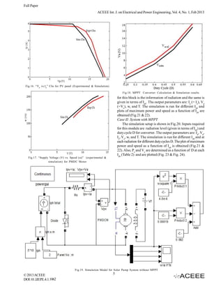
Load Equation: The pump is used to lift water with delivery
head Hd = 5m. The “Speed (ω) vs. Torque (T)” characteristic
is obtained experimentally to derive the pump load equation
(11) which is found to be of the same format mentioned in the
literature [6].
(11)
For PMDC motor, following equations can be written:
(12)
(13)
(14)
Fig.5. “Vp vs. I p”(Exp) of PV panel
TABLE I. VALUES DERIVED FROM PRACTICAL VP-I P C HS FOR SYSTEM WITH MPPT
Using (12) to (14), the load equation (11) can be written in
&R LOAD AT ISC=5.8A terms of Va & Ia as shown in (15).
(15)
The pump load can be represented referred to panel side
(Fig.8 & 9). The referred load equation (16) is obtained using
(5) and (6) in (15).
(16)
70-100W, Total Head: 9 m, Tata BP Solar make. For this unit, Fig.8. System with MPPT and pump load
the following parameters are determined experimentally:
Motor Inertia: 6.83 x 10⁻³ Kgm2, Armature Resistance: 0.7 &!,
Armature Inductance: 0.12 x 10⁻³ H, Voltage constant, Kb =
0.033 V/rad/s (Fig.7).
Fig.9. Motor pump load referred to panel side
Va’-Ia’ characteristics are obtained for different switching
duty cycles (D) and then are superimposed with Vp-Ip charac-
teristics of 148Wp panel at different radiations (Fig.10). The
Fig.6. Solar Pumping with MPPT converter intersection points (operating points) are determined. Using
these values, “ D vs. Va “ (Fig.11) and “ D vs. Pp “ (Fig.12)
characteristics are plotted. It’s observed that at each radia-
tion, power output of the panel is maximum when Va becomes
maximum. Va shows typical increase/decrease trend with the
corresponding variations in Pp. Va corresponding to maxi-
mum power is an unique point. Thus the theoretical infer-
ence, Va following variations of Pp, made for pure resistance
load in section II, is valid for pump load also.
IV. SIMULATION OF THE SYSTEM
This section deals with the simulation of Solar PV water
pumping system considering both the cases: with and without
Fig.7. “ω vs. E b” for PMDC motor the provision of MPPT (Fig.6&13 respectively). Details of
© 2013 ACEEE 3
DOI: 01.IJEPE.4.1.1062](https://image.slidesharecdn.com/1062-130304012626-phpapp01/85/Solar-Photo-Voltaic-Water-Pumping-Harnessing-Maximum-Power-3-320.jpg)
![Full Paper
ACEEE Int. J. on Electrical and Power Engineering, Vol. 4, No. 1, Feb 2013
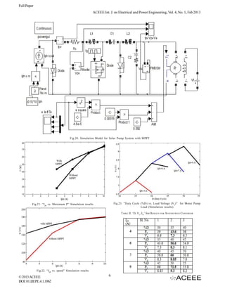
(17) & (18).
(17)
(18)
From experiment, Rs is found to be = 2.13 &!. Iph, being directly
proportional to the radiation, is used as a measure of radiation.
Fig.13. Solar Pumping without MPPT
Fig.10. Panel and Motor-Pump load characteristics superimposed
Fig.14. PV Panel Equivalent Circuit
Fig.11. “Load Voltage Va vs. D (Duty Cycle)” for motor pump load
Fig.15. MPPT Converter
MPPT Converter: It is the same as given in section III
and designed [8] for switching frequency of 20 kHz and duty
cycle range of 0.3 to 0.6. The simulation module is as shown
in Fig.15.
Motor-Pump Unit: Specifications are the same as given
in section III. The DC motor is modeled representing the
permanent magnet as separate excitation with constant
voltage source.
A. Component Simulation
As a first step, simulation of each component is done
independently and verified. Simulation results are in close
conformity with the experimental values for PV panel & Motor
(Fig.16 & Fig.17) and with calculated values for Converter
Fig.12. “Panel Power P p vs. D (Duty Cycle)” for pump load (Fig.18). This establishes validity of the simulation models of
different components considered for simulation are given the components.
below. B. System Simulation
PV Panel: Specifications are the same as given in section
Here two cases are considered: a) Solar Pump System
II. PV panel can be represented by a simple equivalent circuit
without MPPT b) Solar Pump System with MPPT.
[7] with a current source having a diode in parallel and
Case I: System without MPPT
resistance Rs in series. The simulation module is as shown in
PV panel is connected directly to the motor-pump unit
Fig.14. The current and power are given by the equations
and the simulation setup is shown in Fig.19. Input required
© 2013 ACEEE 4
DOI: 01.IJEPE.4.1.1062](https://image.slidesharecdn.com/1062-130304012626-phpapp01/85/Solar-Photo-Voltaic-Water-Pumping-Harnessing-Maximum-Power-4-320.jpg)
![Full Paper
ACEEE Int. J. on Electrical and Power Engineering, Vol. 4, No. 1, Feb 2013
REFERENCES [4] Van Der Merwe L. etal; ‘Maximum power point tracking-
implementation strategies’ IEEE Int Symp on Ind Electronics,
[1] Short T. D., Mueller M. A.; ‘Solar powered water pumps: 1998, vol 1, pp: 214 - 217
problems, pitfalls and potential’, International Conference on [5] Cristinel Ababei et al “Toward integrated PV panels and power
PEMD, 2002, pp280–285. electronics using printing technologies” Solar Energy, July 2010,
[2] Surendra T.S., Subbaraman S. V. V.; ‘Solar PV water pumping 1111–1123.
comes of age in India’ IEEE Photovoltaic Specialists [6] Mohanlal Kolhe et al “Performance Analysis of a Directly
Conference, 2002, pp1485 – 1488. Coupled Photovoltaic Water-Pumping System” IEEE
[3] Vongmanee V. etal; ‘Vector control of induction motor drive Transactions on Energy Conversion, Vol. 19, No. 3, September
system supplied by pv arrays’ IEEE Int Conf on Commn, 2004, 613-618
Circuits and Systems, 2002, vol 2, pp1753-1756 [7] A. A. Ghoneim; “Design Optimization of Photovoltaic Powered
Water Pumping Systems”, Elsevier Energy Conversion and
Management, 47 (2006), 1449-1463.
[8] M. H. Rashid; ‘Power Electronics’, 3rd Edition, 2004, PHI
Ltd-Pearson Publication.
© 2013 ACEEE 8
DOI: 01.IJEPE.4.1.1062](https://image.slidesharecdn.com/1062-130304012626-phpapp01/85/Solar-Photo-Voltaic-Water-Pumping-Harnessing-Maximum-Power-8-320.jpg)


![[1] a control of stand alone photovoltaic water](https://cdn.slidesharecdn.com/ss_thumbnails/1acontrolofstand-alonephotovoltaicwater-200723180816-thumbnail.jpg?width=640&height=640&fit=bounds)