![Contents
Names of things and what they do ................4 Saving a control map on your computer................................................ 23
Loading a control map ........................................................................ 23
Panel .................................................................................................. 4
Loading a memory set as a control map ................................................ 23
Side panel ........................................................................................... 7
Importing a memory set ........................................................... 23
Using control maps ........................................8 Parameter setting items ....................................................................... 24
NO ASSIGN.......................................................................... 24
What is a control map?......................................................................... 8
Channel Message ................................................................... 24
Control maps and the current memory..................................................... 8
System Realtime/F6 [F6/F8/FA/FB/FC/FF]............................... 28
Switching control maps ......................................................................... 9
System Ex. [F0...F7] ................................................................ 29
Saving a control map............................................................................ 9
Free Message [...]................................................................... 30
Receiving a control map from your computer (Bulk Receive) ..................... 10
Tempo ................................................................................... 30
Saving control map data on your computer (Bulk Transmit) ...................... 12
Protecting the control maps .................................................................. 13
Playing (Play mode) .................................... 32
Using PCR Editor...........................................14 Go ahead and play............................................................................ 32
Convenient performance functions ........................................................ 32
Setting the MIDI ports.......................................................................... 14
Selecting the current channel (MIDI transmit channel) .............................. 33
Windows users ....................................................................... 15
MIDI channel.......................................................................... 33
Mac OS X users...................................................................... 15
Selecting sounds (Program Change/Bank)............................................. 34
Explanation of the menus..................................................................... 16
Program Change .................................................................... 34
File menu ............................................................................... 16
Bank Select ............................................................................ 35
Edit menu............................................................................... 16
Selecting the Lower and Upper sounds.................................................. 36
Communication menu .............................................................. 16
Selecting the Lower sound........................................................ 36
Options menu......................................................................... 16
Selecting the Upper sound ....................................................... 36
Help menu ............................................................................. 16
Layering two sounds (Dual).................................................................. 37
Keyboard shortcuts ............................................................................. 17
Playing two sounds in combination (Split) .............................................. 37
Explanation of each window................................................................ 18
Employing performance dynamics (Velocity) .......................................... 38
Main window ......................................................................... 18
Specifying a fixed velocity (Key Velocity) ................................... 38
Message assignment window ................................................... 18
Changing the keyboard touch (Velocity Curve) ........................... 38
Using PCR Editor to assign MIDI messages ............................................ 20
Sending the current value of all controllers (Snapshot) ............................. 39
Assigning a MIDI message ....................................................... 20
Muting the controller values (PRM MUTE) .............................................. 39
Viewing the assigned MIDI messages ........................................ 21
When “stuck notes” occur (Panic) ......................................................... 40
Transferring data between PCR Editor and the PCR................................. 22
Sending ................................................................................. 22
Receiving ............................................................................... 22
2](data:image/gif;base64,R0lGODlhAQABAIAAAAAAAP///yH5BAEAAAAALAAAAAABAAEAAAIBRAA7)
More Related Content
What's hot
What's hot (20)
Similar to A Pcr 300 500 800 Om
Similar to A Pcr 300 500 800 Om (20)
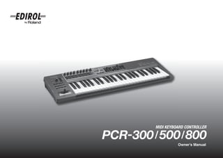
A Pcr 300 500 800 Om
- 2. Contents Names of things and what they do ................4 Saving a control map on your computer................................................ 23 Loading a control map ........................................................................ 23 Panel .................................................................................................. 4 Loading a memory set as a control map ................................................ 23 Side panel ........................................................................................... 7 Importing a memory set ........................................................... 23 Using control maps ........................................8 Parameter setting items ....................................................................... 24 NO ASSIGN.......................................................................... 24 What is a control map?......................................................................... 8 Channel Message ................................................................... 24 Control maps and the current memory..................................................... 8 System Realtime/F6 [F6/F8/FA/FB/FC/FF]............................... 28 Switching control maps ......................................................................... 9 System Ex. [F0...F7] ................................................................ 29 Saving a control map............................................................................ 9 Free Message [...]................................................................... 30 Receiving a control map from your computer (Bulk Receive) ..................... 10 Tempo ................................................................................... 30 Saving control map data on your computer (Bulk Transmit) ...................... 12 Protecting the control maps .................................................................. 13 Playing (Play mode) .................................... 32 Using PCR Editor...........................................14 Go ahead and play............................................................................ 32 Convenient performance functions ........................................................ 32 Setting the MIDI ports.......................................................................... 14 Selecting the current channel (MIDI transmit channel) .............................. 33 Windows users ....................................................................... 15 MIDI channel.......................................................................... 33 Mac OS X users...................................................................... 15 Selecting sounds (Program Change/Bank)............................................. 34 Explanation of the menus..................................................................... 16 Program Change .................................................................... 34 File menu ............................................................................... 16 Bank Select ............................................................................ 35 Edit menu............................................................................... 16 Selecting the Lower and Upper sounds.................................................. 36 Communication menu .............................................................. 16 Selecting the Lower sound........................................................ 36 Options menu......................................................................... 16 Selecting the Upper sound ....................................................... 36 Help menu ............................................................................. 16 Layering two sounds (Dual).................................................................. 37 Keyboard shortcuts ............................................................................. 17 Playing two sounds in combination (Split) .............................................. 37 Explanation of each window................................................................ 18 Employing performance dynamics (Velocity) .......................................... 38 Main window ......................................................................... 18 Specifying a fixed velocity (Key Velocity) ................................... 38 Message assignment window ................................................... 18 Changing the keyboard touch (Velocity Curve) ........................... 38 Using PCR Editor to assign MIDI messages ............................................ 20 Sending the current value of all controllers (Snapshot) ............................. 39 Assigning a MIDI message ....................................................... 20 Muting the controller values (PRM MUTE) .............................................. 39 Viewing the assigned MIDI messages ........................................ 21 When “stuck notes” occur (Panic) ......................................................... 40 Transferring data between PCR Editor and the PCR................................. 22 Sending ................................................................................. 22 Receiving ............................................................................... 22 2
- 3. Settings (Edit mode)......................................41 Troubleshooting........................................... 82 Assigning MIDI messages on the PCR keyboard ..................................... 41 Problems with connections................................................................... 82 Note assign............................................................................ 42 Deleting the USB driver ....................................................................... 84 Aftertouch assign .................................................................... 44 Problems while using the PCR .............................................................. 85 Control change assign ............................................................. 46 Program change assign ........................................................... 48 Tempo assign ......................................................................... 52 RPN/NRPN assign .................................................................. 53 Appendix..................................... 87 System exclusive assign ........................................................... 55 Convenient functions ........................................................................... 66 Two MIDI ports ........................................................... 88 Copy assignment .................................................................... 66 Canceling an assignment (NO ASSIGN).................................... 67 Connecting the PCR directly to a sound module ........... 89 Control map list .......................................................... 90 System settings ............................................68 Clock settings..................................................................................... 70 MIDI implementation chart ......................................... 91 F8 Clock On/Off .................................................................... 70 Main specifications ..................................................... 92 F8 Clock Default Tempo........................................................... 70 F8 Clock Port Set .................................................................... 71 Index ......................................................................... 93 Keyboard settings ............................................................................... 72 Keyboard Velocity Curve ......................................................... 72 Keyboard Port Set ................................................................... 74 Keyboard Aftertouch Curve ...................................................... 74 Pad settings ....................................................................................... 75 Pad Velocity Curve.................................................................. 75 Pad Aftertouch Curve............................................................... 75 MIDI settings ...................................................................................... 76 Before using this unit, carefully read the sections entitled: “USING THE UNIT MIDI I/F Switch ...................................................................... 76 SAFELY” and “IMPORTANT NOTES” (separate sheet). They provide important MIDI Merge Destination ........................................................... 77 information concerning the proper operation of the unit. Additionally, in order Advanced Driver Switch........................................................... 78 to feel assured that you have gained a good grasp of every feature provided Control map settings ........................................................................... 79 by your new unit, Owner’s manual should be read in its entirety. The manual Startup Memory ...................................................................... 79 should be saved and kept on hand as a convenient reference. VALUE knob settings ........................................................................... 80 VALUE encoder....................................................................... 80 Other settings..................................................................................... 81 * All product names mentioned in this document are trademarks or registered trademarks of their Dynamic Mapping/V-LINK ....................................................... 81 respective owners. H-activity On/Off.................................................................... 81 Factory Reset .......................................................................... 81 Copyright © 2007 ROLAND CORPORATION All rights reserved. No part of this publication may be reproduced in any form without the written permission of ROLAND CORPORATION. 3
- 4. Names of things and what they do Panel fig.Panel-Left.eps 1 Display This shows a variety of information, such as the current state. Indication Summary When you operate a controller, the value of the parameter assigned to that controller is briefly displayed. Information Alphanumeric characters such as MIDI channels and program changes are also dis- played. DYNAMIC MAPPING This will light when DYNAMIC MAPPING is active. This will light when the PCR is connected to your computer USB via USB. 1 This will blink when a MIDI message is transmitted from DATA OUT USB or MIDI OUT. This will light when the value shown in the display is a hexa- HEX 4 decimal value. 5 * The display will dim if you leave the PCR without operating it for several seconds. 2 6 * The explanations in this manual include illustrations that depict what should typically be 3 7 shown by the display. Note, however, that your unit may incorporate a newer, enhanced version of the system, so what you actually see in the display may not always match what appears in the manual. 8 2 [DYNAMIC MAPPING] button, [V-LINK] button When you press the [DYNAMIC MAPPING] button, “DYNAMIC MAPPING” or 9 10 11 12 “V-LINK” will turn on. The function of the [DYNAMIC MAPPING] button is specified by the System setting 13 14 15 DYNAMIC MAPPING/V-LINK (p. 81). DYNAMIC MAPPING Dynamic Mapping is an extended function for future use. For details, refer to the Roland website. V-LINK V-LINK ( ) is a function that allows music and images to be performed 16 together. By using MIDI to connect two or more V-LINK compatible devices, you can easily enjoy a wide range of visual effects that are linked to the expressive elements of a music performance. 4
- 5. Names of things and what they do 3 VALUE knob 11 [LOWER] button, [DATA] button By turning the VALUE knob you can change the value of the MIDI CHANNEL, Use this button when you want to play or make settings for the Lower part. PROGRAM CHANGE, CONTROL MAP, or USER. If the [LOWER] button is lit, the keyboard (notes and aftertouch), bender lever In Edit mode, use this knob to select the item that you want to edit. (pitch bend, modulation), foot pedal messages, and program change messages will be transmitted on the current channel specified for the Lower part. 4 [MIDI CHANNEL] button (-> Selecting the Lower and Upper sounds (p. 36)) After pressing the [MIDI CHANNEL] button so it’s lit, you can turn the VALUE knob to specify the channel on which the keyboard and bender will transmit messages. 12 [UPPER] button, [CHK SUM] button (-> Selecting the current channel (MIDI transmit channel) (p. 33)) Use this button when you want to play or make settings for the Upper part. If the [UPPER] button is lit, the keyboard (notes and aftertouch), bender lever (pitch 5 [PROGRAM CHANGE] button bend, modulation), foot pedal messages, and program change messages will be After pressing the [PROGRAM CHANGE] button so it’s lit, you can turn the VALUE transmitted on the current channel specified for the Upper part. knob to transmit a program change message on the current channel. (-> Selecting the Lower and Upper sounds (p. 36)) (-> Selecting sounds (Program Change/Bank) (p. 34)) 13 [EDIT] button 6 [CONTROL MAP] button Use this button to assign MIDI messages to the controllers or to make system After pressing the [CONTROL MAP] button so it’s lit, you can turn the VALUE knob settings. to switch among control maps stored in the PCR. (-> Assigning MIDI messages on the PCR keyboard (p. 41)) (-> Switching control maps (p. 9)) (-> System settings (p. 68)) 14 [PRM MUTE] button, [ENTER] button 7 [USER] button After pressing the [USER] button so it’s lit, you can turn the VALUE knob to change Use this to mute controller message output. the value of a user-assigned parameter. When you’re not in Play mode, you can use this as the [ENTER] button. (-> VALUE knob settings (p. 80)) 15 OCTAVE [-]/[+] buttons, [BACK] button, [CANCEL] 8 Controllers [L1]–[L4] (buttons) button You can assign the desired MIDI messages to these buttons. Use these buttons to raise or lower the octave of the keyboard. (-> Assigning a MIDI message (p. 20)) When you’re not in Play mode, you can use these as the [BACK] button, which returns you to the previous setting, and the [CANCEL] button, which cancels the 9 [AFTERTOUCH] button setting. This specifies whether the keyboard will (ON) or will not (OFF) transmit aftertouch messages. 16 Bender lever, [BEND] and [MOD] controller You can use this to modify the pitch or to apply vibrato. 10 [DUAL/SPLIT] button You can also assign the desired MIDI messages to this controller. This switches between Dual mode and Split mode. (-> Assigning MIDI messages on the PCR keyboard (p. 41)) (-> Layering two sounds (Dual) (p. 37)) (-> Playing two sounds in combination (Split) (p. 37)) 5
- 6. Names of things and what they do fig.Panel-Top.eps 17 21 18 19 20 22 23 17 Controllers [R1]–[R9] (knobs) 20 [HEX] button You can assign the desired MIDI messages to these knobs. When you’re not in Play mode, you can press this button to switch to hexadecimal (-> Assigning a MIDI message (p. 20)) input mode (p. 64). When you’re in Play mode (p. 32), this button will function as a conventional 18 Controllers [A1]–[A9], [B1]–[B9] (pads) controller [B9]. You can assign the desired MIDI messages to these pads. (-> Assigning a MIDI message (p. 20)) 21 Controllers [H1], [H2] (crossfader) The force with which you press these controllers can be used to transmit a You can assign the desired MIDI messages to this crossfader. corresponding velocity value or aftertouch value. (-> Assigning a MIDI message (p. 20)) When you’re not in Play mode, you can use these buttons as [0]–[9] and [A]–[F] buttons to enter numeric values. 22 Controllers [C1]–[C3] (buttons) You can assign the desired MIDI messages to these buttons. 19 [DECIMAL] button (-> Assigning a MIDI message (p. 20)) When you’re not in Play mode, you can press this button to switch to decimal input mode (p. 64). 23 Controllers [S1]–[S9] (sliders) When you’re in Play mode, this button will function as a conventional controller You can assign the desired MIDI messages to these sliders. [A9]. (-> Assigning a MIDI message (p. 20)) 6
- 7. Names of things and what they do Side panel fig.Panel-Side.eps 27 MIDI MERGE switch This switches the MIDI IN message Merge function on/off. (-> MIDI Merge Destination (p. 77)) 28 MIDI IN/OUT connectors You can connect these to the MIDI connectors of other MIDI devices in order to transmit and receive MIDI messages. (-> MIDI settings (p. 76)) 29 Controllers [P1], [P2] (foot pedals) You can connect suitable pedals to these jacks and use them as controllers. You can connect a separately available pedal switch (DP-2, BOSS HOLD 24 25 26 27 28 29 30 FS-5U) here and use it as a hold pedal. You can connect a separately available expression pedal (EV-5, EXPRESSION EV-7) here and use it to control the tone or volume in real time. 24 DC IN jack You can connect a separately available AC adaptor (p. 92) to this jack. If you You can assign the desired MIDI messages to these controllers. wish to purchase an AC adaptor, please contact your dealer. (-> Assigning a MIDI message (p. 20)) 25 Power switch * Use only the specified expression pedal. By connecting any other expression pedals, you risk causing malfunction and/or damage to the unit. DC Power turned on when using the AC adaptor OFF Power switched off 30 Security slot ( ) Power turned on when a USB cable is connected http://www.kensington.com You can use the USB (i.e., bus power) setting if the PCR-300/500/ 800 is connected to your computer via a USB cable. The power will be supplied from the computer via the USB cable. USB If you want to use the PCR on bus power, set the power switch to the USB position. * With some computers, the PCR may not operate on bus power. If so, you’ll need to use the separately available AC adaptor (p. 92). 26 USB connector Use this if you’re connecting the PCR to your computer via a USB cable. 7
- 8. Using control maps What is a control map? The PCR-300/500/800 have fifty fully assignable controllers; you can freely assign You can also download the latest control maps from the Roland website and load them any MIDI message to each of these controllers. into the PCR. The MIDI settings assigned to the controllers are collectively called a “control map.” This is the same as what was called a “memory set” on previous models of the PCR series. Memory Sets and Control Maps The “memory sets” in earlier models of the PCR series are now called “control maps” For details on how to assign MIDI messages to controllers, refer to Using PCR Editor (p. 14) or Assigning MIDI messages on the PCR keyboard (p. 41). on the PCR-300/500/800. Using the PCR Editor version 2 software included with this product, you can import MIDI settings that are assigned to the controllers (i.e., the control map) can be stored “memory sets” and use them as “control maps.” in the PCR’s own memory or in DAW software on your computer. Simply by switching For details, refer to Using PCR Editor (p. 14). control maps, you can control a wide range of applications. Control maps and the current memory About the PCR’s memory fig.CurrentMemory-e.eps The PCR-300/500/800 holds sixteen control maps in its internal memory. In order to Control maps use a control map, you must copy it into a location called “the current memory.” SONAR Any changes you make to the contents of the current memory will be lost when you Logic turn off the power. If you want to keep the changes you’ve made to the current Cubase memory, refer to Saving a control map (p. 9). : : etc... You can use the Startup Memory (p. 79) to specify which control map should be loaded into current memory when the power is turned on. Current Memory 8
- 9. Using control maps Switching control maps Saving a control map When the PCR-300/500/800 is shipped from the factory, it contains sixteen control If you want to keep the changes you’ve made to the current memory, use the following maps. By switching among these control maps, you can quickly select control maps procedure to save the control map. that are suitable for a wide variety of software. For details on the memory numbers of You can save the control map in memory numbers 1–F. You can’t save to memory these control maps and their factory settings, refer to Control map list (p. 90). number 0. fig.H-MemorySet.eps * If you’ve changed the settings of the current memory, be sure to “SAVE” if you want to keep your changes. 1 Press the [CONTROL MAP] button. fig.H-Edit.eps The [CONTROL MAP] button will light. The display will indicate the currently selected 1 Press the [EDIT] button so it’s lit. memory number. 2 Turn the [VALUE] dial to select the memory number you want to call up. fig.D-Edit.eps The display will indicate “EDIT.” fig.D-Save.eps 2 Turn the VALUE knob to make the display indicate “SAVE.” fig.D-Protect.eps 3 Press the [ENTER] button. * If the display indicates “PTC,” the Protect setting is ON, and you’ll be unable to save the memory. Turn the Protect setting OFF, and repeat the procedure from step 1. (-> Protecting the control maps (p. 13)) You can also switch control maps using the following method. 4 Use the VALUE knob or controllers [A1]–[A8] and [B1]–[B8] to specify the 1. Press the [EDIT] button so it’s lit. The display will indicate “EDIT.” memory number “1”–”F” in which you want to save the control map. The specified memory number will blink in the display. 2. Press the [CONTROL MAP] button. It will light, and the display will indicate the currently selected memory number. 5 Press [ENTER] to save the control map. 3. Use controllers [A1]–[A8], [B1]–[B8], or the VALUE knob to specify the * If you press another button instead of the [ENTER] button, the Save operation will be cancelled. memory number you want to call up. 4. Press the [ENTER] button. 9
- 10. Using control maps Receiving a control map from your computer (Bulk Receive) The PCR-300/500/800 can receive control map data in the form of a bulk dump. 4 Verify that the display indicates “BLR” (Bulk Receive), and then press the [ENTER] If you want control map data you’ve created using PCR Editor to be received into the button. PCR’s current memory, you’ll need to make settings in PCR Editor so that the PCR will If the display indicates “BLT” (Bulk Transmit), use the VALUE knob to make it be ready to receive a bulk dump. If you want the PCR to receive this data as messages indicate “BLR” (Bulk Receive). from your DAW software, you’ll need to make settings on the PCR keyboard so that it will be ready to receive a bulk dump. Here we’ll explain how to make settings on the PCR keyboard so that it will be able 5 Use the VALUE knob or the controllers to choose the reception method. Choose the method that’s appropriate for the data you’ll be receiving. to receive a bulk dump. For more about PCR Editor, refer to Using PCR Editor (p. 14). For details on how Controller Item Display Explanation to receive a control map from PCR Editor, refer to Transferring data between PCR One control map will be received. Editor and the PCR (p. 22). SINGLE The received data will overwrite the [A1 (0)] BULK current memory. fig.H-Edit.eps Memories 1–F will not be affected. 1 Press the [EDIT] button so it’s lit. Data for all fifteen control maps will [A2 (1)] ALL BULK be received. The received data will overwrite internal memories 1–F. fig.D-RSBulk-Wait.eps 6 Verify that the display indicates the correct choice, and press the [ENTER] button. The rightmost digit of the display will blink, and the PCR will wait for bulk data to arrive. fig.D-Edit.eps The display will indicate “EDIT.” About the display in Bulk mode fig.D-Bulk.eps 2 Turn the VALUE knob to make the display indicate “BULK.” Receive/Transmit Receive Transmit fig.D-BulkR.eps SINGLE BULK / ALL BULK 3 Press the [ENTER] button. “BLR” will blink in the display (Bulk Receive). SINGLE ALL BULK BULK Transmitting/Receiving/Waiting Receiving Receive Transmit Waiting Waiting Transmitting (blinking) (blinking) 10
- 11. Using control maps 7 Operate PCR Editor or your DAW software to transmit the control map data. Select “EDIROL PCR” as the MIDI output device for PCR Editor or your DAW software. For details on how to make this setting in your DAW software, refer to the owner’s manual for the DAW software you’re using. fig.D-End.eps 8 When the PCR has finished receiving the control map data, the display will indicate “END.” Press the [ENTER] button to complete the operation. Error indication If the data was not received correctly, “ERR” will be blinking in the display. If this occurs, press the [CANCEL] button and perform the procedure again from step 1. Control map data received as Single Bulk will be loaded into the current memory, meaning that it will be lost when you turn off the power. However, if you save this control map into one of the internal memories, you won’t need to re-transmit it to the PCR. Refer to Saving a control map (p. 9). 11
- 12. Using control maps Saving control map data on your computer (Bulk Transmit) The PCR-300/500/800 can transmit control map data to your DAW software in the Controller Item Display Explanation form of a bulk dump. In order to transmit a control map you’ve edited on the PCR keyboard to PCR Editor [A1 (0)] BULK RECEIVE Receive bulk data or other software you’re using, you’ll need to make settings on the PCR to make it transmit the bulk data. For more about PCR Editor, refer to Using PCR Editor (p. 14). For details on how [A2 (1)] BULK TRANSMIT Transmit bulk data to transmit a control map from PCR Editor, refer to Transferring data between PCR Editor and the PCR (p. 22). fig.H-Edit.eps 5 Press the [ENTER] button. 1 Press the [EDIT] button so it’s lit. 6 Use the VALUE knob or controllers to choose the type of transmission. Choose the type of data you want to transmit. Controller Item Display Explanation The control map data of the current [A1 (0)] SINGLE BULK memory will be transmitted. fig.D-Edit.eps The display will indicate “EDIT.” Data for all fifteen control maps in [A2 (1)] ALL BULK internal memory (memories 1–F) will be transmitted. fig.D-Bulk.eps 2 Turn the VALUE knob to make the display indicate “BULK.” fig.D-TSBulk-Wait.eps 7 Check the indication in the display, then press the [ENTER] button. fig.D-BulkR.eps The rightmost digit of the display will blink, and the PCR will wait to 3 Press the [ENTER] button. transmit bulk data. “BLR” will blink in the display (Bulk Receive). fig.D-BulkT.eps 8 Put PCR Editor or your DAW software in recording mode, and then press the 4 Turn the VALUE knob to make the display indicate “BLT” (Bulk PCR’s [ENTER] button. Data transmission will begin. Transmit). Choose “EDIROL PCR 2” as the MIDI input port for PCR Editor or your DAW Alternatively, you can press controller [A2 (1)] instead of using the software. For details on how to make this setting in your DAW software, refer to VALUE knob. the owner’s manual for the software you’re using. fig.D-End.eps 9 When the PCR has finished transmitting the control map data, the display will indicate “END.” Press the [ENTER] button to complete the operation. You’ll also need to stop recording on your DAW software. 12
- 13. Using control maps Protecting the control maps By turning the Protect setting on, you can protect the control map data from being accidentally overwritten. This will disable All Bulk reception (p. 10) and Save (p. 9) operations, protecting your valuable data from being overwritten. The Protect on/off setting is remembered even when the PCR is powered off. fig.H-Edit.eps 1 Press the [EDIT] button so it’s lit. fig.D-Edit.eps The display will indicate “EDIT.” fig.D-Protect.eps 2 Turn the VALUE knob to make the display indicate “PTC.” 3 Check the indication in the display, then press the [ENTER] button. The display will indicate the current protect status. Controller Item Display Explanation Control map data in internal mem- [A1 (0)] PROTECT OFF ory can be rewritten. Control map data in internal mem- [A2 (1)] PROTECT ON ory cannot be rewritten. 4 Use the VALUE knob to choose the desired setting, and press the [ENTER] button. 13
- 14. Using PCR Editor PCR Editor Ver. 2 is an application that lets you use your computer to create control The PCR-300/500/800 has a total of fifty controllers: [R1]–[R9], [S1]–[S9], [A1]– maps (called “memory sets” on earlier models of the PCR series) for the EDIROL PCR [A9], [B1]–[B9], [C1]–[C3], [L1]–[L4], [H1]–[H2], [P1]–[P2], [BEND], [MOD], and series. [AFTERTOUCH]. You can freely assign the MIDI message that will be transmitted by fig.controller.eps each of these controllers. Although it is possible to make MIDI message assignments on the PCR itself (-> Assigning MIDI messages on the PCR keyboard (p. 41)), it’s easiest to use PCR Editor, since this allows you to easily assign messages in a graphical screen that resembles the PCR’s panel. The fifty messages assigned to the controllers are collectively called a “control map.” PCR Editor Ver. 2 lets you edit control map data and transfer it between the PCR and your computer, and also save or load control map settings as SMF data. Setting the MIDI ports In order to transfer control maps between PCR Editor and the PCR, you’ll need to * The explanation that follows is for when the PCR is connected via USB. If you’re using a MIDI specify the MIDI ports that PCR Editor is to use. connection, specify the MIDI input port and MIDI output to which your PCR is MIDI-connected instead of “EDIROL PCR 2” and “EDIROL PCR.” What are MIDI ports? Input ports Output ports Input port Explanation Output port Explanation EDIROL PCR MIDI IN Receives data that arrives at the PCR’s MIDI IN connector. Transmits MIDI messages to the device connected to the PCR’s EDIROL PCR MIDI OUT Receives data from the PCR’s sliders, knobs, and buttons that MIDI OUT connector. EDIROL PCR 1 are assigned to “PORT 1.” Transmits MIDI messages to the PCR. Receives data from the PCR’s sliders, knobs, and buttons that EDIROL PCR If you’re sending bulk data to the PCR, choose “PCR” as the are assigned to “PORT 2.” output port. EDIROL PCR 2 If you’re receiving bulk data from the PCR, choose “PCR 2” as the input port. In order to send a control map you’ve created in PCR Editor to the PCR so that it can be used, you’ll need to select “PCR” as the output port. The output destination for the MIDI messages sent when you operate the PCR’s sliders, knobs, and buttons can be specified independently for each controller. For details, refer to Two MIDI ports (p. 88). 14
- 15. Using PCR Editor Windows users Mac OS X users If you have not yet installed PCR Editor in your computer, install it now as If you have not yet installed PCR Editor in your computer, install it now as described in the included setup guide. described in the included setup guide. 1 Use a USB cable to connect the PCR to your Mac, then switch on the PCR’s 1 Use a USB cable to connect the PCR to your computer, then switch on the PCR’s power. power. 2 From the Mac Finder, open the [Applications]-[PCR Editor V2] folder, and 2 In Windows, choose [Start]-[All Programs]-[PCR Editor V2]-[PCR Editor 2] to start double-click PCR Editor V2 to start up PCR Editor. up PCR Editor. 3 In PCR Editor, choose [Options]-[MIDI Devices]. 3 In PCR Editor, choose [Options]-[MIDI Devices]. fig.MacMIDIPort-e.eps fig.WinMIDIPort-e.eps 4 In the MIDI Devices dialog box, make the MIDI 4 In the MIDI Devices dialog box, make the MIDI device settings shown in the illustration. device settings shown in the illustration. 5 Click [OK] to close the dialog box. 5 Click [OK] to close the dialog box. * Microsoft and Windows are registered trademarks of Microsoft Corporation. * Apple and Macintosh are registered trademarks of Apple Computer, Inc. * The screen shots in this document are used in compliance with the guidelines of the Microsoft * Mac OS is a trademark of Apple Computer, Inc. Corporation. * Windows® is known officially as: “Microsoft® Windows® operating system.” 15
- 16. Using PCR Editor Explanation of the menus File menu Communication menu Menu Explanation Menu Explanation Creates a new control map. Transmits the control map currently being edited to the current New In the new control map, all controllers will be set to “NO AS- memory of the PCR keyboard. Transmit SIGN.” For details, refer to Transferring data between PCR Editor and the Loads a control map that was saved in SMF format. PCR (p. 22). Open For details, refer to Loading a control map (p. 23). Receives the current memory of the PCR into PCR Editor. Saves the control map currently being edited by overwriting the Receive For details, refer to Transferring data between PCR Editor and the Save PCR (p. 22). original SMF. Saves the control map currently being edited in SMF format with Save As the name you specify. For details, refer to Saving a control map on your computer (p. 23). Import Memory Set Loads a memory set created in PCR Editor version 1 as a version Options menu 2 control map. Exports an HTML-format list of the messages assigned to each con- troller of the control map currently being edited. Menu Explanation Export Assign List * The HTML file created by this command cannot be loaded by Specifies the MIDI ports used to communicate with the PCR key- means of [File]-[Open]. MIDI Devices board. Displays an HTML-format list of the messages assigned to each For details, refer to Setting the MIDI ports (p. 14). View Assign List controller of the control map currently being edited. Shows the MIDI message settings assigned to each controller in Show Messages the main window of PCR Editor. For details, refer to Viewing the assigned MIDI messages (p. 21). Edit menu Help menu Menu Explanation Copy Copies the setting of the selected controller to the clipboard. Menu Explanation Paste Pastes the setting from the clipboard to the selected controller. PCR Editor Help Opens the online manual. NO ASSIGN Sets the assignment of the selected controller to “NO ASSIGN.” 16
- 17. Using PCR Editor Keyboard shortcuts You can use the following keyboard shortcuts in PCR Editor. Command Windows Macintosh [File]–[New] Ctrl + N Command + N [File]–[Open] Ctrl + O Command + O [File]–[Save] Ctrl + S Command + S [File]–[Save As] Ctrl + Shift + S Command + Shift + S [File]–[Exit] Alt + F4 Command + Q [Edit]–[Copy] Ctrl + C Command + C [Edit]–[Paste] Ctrl + V Command + V [Edit]–[NO ASSIGN] Del Del Next controller Ctrl + F Command + F Previous controller Ctrl + B Command + B * In some text boxes, such as the main window’s Title field, the [Edit]–[Copy] and [Edit]–[Paste] commands are used for text editing. 17
- 18. Using PCR Editor Explanation of each window Main window Message assignment window fig.EditorMainWindow-e.eps fig.EditorMessageWindow1.epsfig.EditorMessageWindow2.eps 1 2 1 2 3 4 6 7 5 8 * The available items will depend on the controller and on the type of message you assign. 1 Controller name 1 Title Shows the name of the controller you’re editing. You can enter a name for the control map currently being edited. Only single-byte alphanumeric characters can be entered as the control map name. 2 Assign Message The name you enter here is displayed as the title of the HTML file produced by the Lets you select the type of MIDI message to assign to the controller. [File]-[Export Assign List] command. Menu Explanation 2 Controllers NO ASSIGN Cancels the MIDI message assignment Channel Message Assigns a channel message (CC, note, etc.) Click the controller to which you want to assign a MIDI message. When you move the mouse over a controller (i.e., over the clickable area of a controller), the mouse System Realtime/F6 Assigns a system realtime message or F6 (Tune Request) cursor will change to the shape. A message assignment window will open System Ex Assigns a system exclusive message of up to twenty-four bytes when you click the controller in this state. Free Message Assigns a MIDI message of up to twenty-four bytes (multiple messages are allowed) Tempo Assigns tempo control 3 Message assignment fields Here you can specify the value for each parameter of the MIDI message you’ve selected in the Assign Message list 2 . For details on the parameters of each MIDI message, refer to Parameter setting items (p. 24). 18
- 19. Using PCR Editor 4 Output Port 8 Comment This specifies the USB port on the USB-connected computer to which the MIDI You can enter a comment for the assigned message. Only single-byte message will be sent. alphanumeric characters can be used when entering the comment. The comment you enter here is shown in the “PARAMETER” column of the HTML Port Explanation file produced by the [File]-[Export Assign List] command. Port 1 The message will be sent to “EDIROL PCR 1.” * Comments can be loaded only from an SMF file saved by PCR Editor. Port 2 The message will be sent to “EDIROL PCR 2.” The message will be sent to both “EDIROL PCR 1” and “EDIROL Port 1+2 PCR 2.” 5 Button Mode For a button-type controller, this specifies the button’s mode. Mode Explanation Switched on when button is pressed; switched off when button is Unlatch released. Latch Button acts as a toggle, switching on or off each time it’s pressed. Each time you press the button, the value will increment by 1 (or decrement by 1 if the minimum value is higher than the maximum Increase value). When the value has reached the maximum (minimum) val- ue, it will “wrap around” to the minimum (maximum) value. * You can’t select this if the message type is NOTE. 6 Aftertouch Mode If the controller currently being edited is [A1]–[A9] or [B1]–[B9], this specifies the aftertouch setting. Mode Explanation OFF No aftertouch. Channel Pressure Channel aftertouch will be applied to the specified channel. Polyphonic aftertouch will be applied to an individual note Polyphonic Key Pressure number. 7 Virtual Center Click If the controller currently being edited is [R1]–[R9] or [S1]–[S9], this specifies a virtual center click (p. 65). Mode Explanation OFF No “dead zone” near the center. ON “Dead zone” near the center. 19
- 20. Using PCR Editor Using PCR Editor to assign MIDI messages fig.EH-AssignType.eps_25 Assigning a MIDI message 3 According to the type of MIDI message you’ve selected, set the various parameters in Here’s how to assign a MIDI message to each controller. the message assignment area. fig.EH-Assign.eps_81 For details on the parameters, refer to 1 In the main window, click the controller to Parameter setting items (p. 24). which you want to assign a MIDI message. fig.EH-AssignPort.eps_25 4 In the Output Port field, specify the MIDI output port. 5 If desired, use the Comment field to add a fig.EH-AssignMessage.eps_25 comment. 2 In the message assignment window, use the Assign Message field to select the type of MIDI message that you want to assign. 6 Click [OK]. 20
- 21. Using PCR Editor Viewing the assigned MIDI messages Display Meaning NO ASSIGN You can use either of the following two methods to view the MIDI messages you’ve assigned. Note Assignment list Channel Pressure If you want to use your browser to view a list of the assignments for the current control Polyphonic Key Pressure map, choose [File]-[View Assign List]. This method is convenient when you want to see the control map settings at a glance. If you want to save the assignment list as an HTML Control Change file, choose [File]-[Export Assign List]. The “Save As” dialog box will appear; specify the save destination, assign a file name, and click [Save]. Program Change Viewing the assigned messages Program Change (Min-Max) If you want the current settings to be shown on each controller in the main window, Bank Select + Program Change choose [Options]-[Show Messages], and add a check mark next to [Show Messages]. This method shows the current settings in simplified form as follows. Program Change - Dec fig.EditorViewAssign-e.eps Program Change - Inc RPN NRPN Encoder Simulate System Realtime/F6 System Ex. Free Message Tempo The color of the indication shows the Output Port setting. Color Output Port Yellow Port 1 Light blue Port 2 Light green Ports 1+2 Pink NO ASSIGN 21
- 22. Using PCR Editor Transferring data between PCR Editor and the PCR Sending Receiving If you’ve used PCR Editor to create control map settings and want to use them on the If you want to use PCR Editor to edit a control map that’s currently in the PCR PCR keyboard, you’ll need to send the control map currently being edited to the PCR’s keyboard, you’ll need to load the control map from the PCR’s current memory into PCR current memory as described below. Editor so that it can be edited. Proceed as follows: fig.EditorR1-e.eps * When you send this data, the PCR’s current memory will be overwritten. If you want to preserve the settings of the PCR’s current memory, you must save them as one of the internal control maps. 1 From the menu bar, choose [Communication]- (-> Saving a control map (p. 9)) [Receive]. fig.EditorT1-e.eps 1 From the menu bar, choose [Communication]- [Transmit]. fig.EditorR2-e.eps 2 A confirmation dialog box will appear. Click [Continue]. fig.EditorT2-e.eps 2 A confirmation dialog box will appear. Click [Continue]. fig.EditorR3-e.eps 3 The Receive Control Map dialog box will appear. As instructed by the dialog box, transmit bulk data fig.EditorT3-e.eps from the PCR. 3 The Transmit Control Map dialog box will appear. As instructed by the dialog box, set the PCR to wait for bulk data to be received. fig.EditorR4-e.eps 4 When you’re ready, click [Continue]. 4 A dialog box will indicate that the data is being transferred. fig.EditorR4-e.eps When the dialog box disappears, reception has 5 A dialog box will indicate that the data is being been completed. transferred. When the dialog box disappears, transmission has 5 The PCR’s display will indicate “END.” Press the been completed. PCR’s [ENTER] button to return to Play mode. 6 The PCR’s display will indicate “END.” Press the PCR’s [ENTER] button to return to Play mode. 22
- 23. Using PCR Editor Saving a control map on your computer Loading a memory set as a control map A control map that you edit using PCR Editor can be saved as an SMF-format file on A “memory set (SMF file)” created for an earlier model in the PCR series can be loaded your computer, as well as being transferred to or from the PCR keyboard. as a “control map” for the PCR-300/500/800. * The comments that have been entered for the controllers are also saved in the SMF. To save a control map as an SMF file, proceed as follows. Importing a memory set 1 From the menu bar, choose [File]-[Save As]. Controllers that do not exist on earlier models of the PCR series will be set to “NO If you want to save the settings while overwriting the file that was most recently ASSIGN.” opened, choose [File]-[Save]. * You can’t load an SMF that does not contain memory set data for an earlier model of the PCR series. The SMF must contain settings for all controllers of the earlier PCR series model. 2 Specify a file name and click [Save]. Here’s how to import a memory set. 1 From the menu bar, choose [File]-[Import Memory Set]. Loading a control map 2 Specify the file that you want to load, and click [Open]. You can load control map data that was saved in SMF format. * You can’t load an SMF that does not include PCR control map data. The SMF must contain settings for all controllers. * The contents of the comment field can be loaded only from an SMF file that was saved by PCR Editor. Here’s how to load a control map from an SMF file. 1 From the menu bar, choose [File]-[Open]. 2 Specify the SMF file that you want to load, and click [Open]. 23
- 24. Using PCR Editor Parameter setting items The setting items shown in the message assign window will depend on the MIDI message you’ve selected. This section explains the setting items for each MIDI message. Values for parameters are specified in decimal. * Within the explanation, values in square brackets [ ] are in hexadecimal. NO ASSIGN Channel Message Clears any message assignment. Assigns a channel message. Channel Pressure [Dn vv] No message will be sent even if you operate a Use the Type field to select the type of message you Assign a channel pressure message. controller that’s set to NO ASSIGN. want to assign. According to the message you’ve fig.EditorChPres.eps_35 fig.EditorNoAssign.eps_35 selected, set the following parameters. Note [9n kk vv] Assign a note message. fig.EditorChannelMessage.eps_35 You can specify the following parameters for NO ASSIGN has no parameters to set. Channel Pressure. Item Content MIDI Channel MIDI channel [n] You can specify the following parameters for Note. Lower value [vv] of channel Min Value pressure Item Content Upper value [vv] of channel Max Value MIDI Channel MIDI channel [n] pressure Note Number Note number [kk] Velocity Velocity [vv] AFT Mode Aftertouch 24
- 25. Using PCR Editor Channel Message Polyphonic Key Pressure [An kk vv] Control Change [Bn cc vv] Program Change [Cn pp] Assign a polyphonic key pressure message. Assign a control change message. Assign a program change message (with a fixed fig.EditorPolyKeyPres.eps_35 fig.EditorCC.eps_35 program number). fig.EditorPC1.eps_35 You can specify the following parameters for You can specify the following parameters for Control Polyphonic Key Pressure. Change. You can specify the following parameters for Program Change. Item Content Item Content MIDI Channel MIDI channel [n] MIDI Channel MIDI channel [n] Item Content Note Number Note number [kk] Control Number Control number [cc] MIDI Channel MIDI channel [n] Lower value [vv] of key Lower limit of the control PC Number Program number [pp] Min Value Min Value pressure value [vv] Upper value [vv] of key Upper limit of the control * The range of the program number [pp] is 1–128. Max Value Max Value pressure value [vv] 25
- 26. Using PCR Editor Channel Message Program Change (Min-Max) [Cn pp] Bank Select + Program Change Program Change – Dec Assign a program change message (with a variable [Bn 00 mm Bn 20 ll Cn pp] Assign the program change decrement function (PC program number). Assign a bank select message and program change DEC). fig.EditorPC2.eps_35 message (all values fixed). This will transmit a program change number that is fig.EditorBankSelect.eps_35 one less than the program change number most recently transmitted in the PCR’s program change mode. fig.EditorPCDec.eps_35 You can specify the following parameters for Program Change (Min-Max). You can specify the following parameters for Bank Select + Program Change. Item Content MIDI Channel MIDI channel [n] Item Content There are no parameters to specify for Program Lower limit of the program Min Number MIDI Channel MIDI channel [n] Change – Dec. number [pp]. Bank MSB Bank number MSB [mm] Upper limit of the program Max Number Bank LSB Bank number LSB [ll] number [pp]. PC Number Program number [pp] * The range of the program number [pp] is 1–128. * The range of the program number [pp] is 1–128. 26