A Novel Design and Computational Fluid Dynamics of Swirl Flow Enhancing Device in Intake of IC Engine

The present paper work is directed to a device located at the intake port at the junction of the intake manifold and the engine head. This location allows the device to be used with any type of carburetor or fuel injection system. It is the object of the present device to utilize at least three fixed, helically twisted blades to impart additional swirl mixing of the fuel/air mixture. This fuel/air mixture has already been pre-heated by its travel through the intake manifold. The "violent swirl" created by the device provides a more uniform fuel/air mixture, thereby causing a more complete and efficient combustion. The overall result of using the device is better gas mileage, increased performance, easier starting, and less pollution. The object of the project work to improve the fuel/air mixture of the fuel injected engines, preventing valves from being burned or eroded by clogged injectors. As a result of forcing the air to enter the intake port in a high velocity swirl, there is disruption of any direct fuel streams upon the head of the cylinder intake valve which occur as a result of clogged injectors. Another object of the project work is to provide a device that improves the homogeneity of the fuel/air mixture delivered by the carburetor to the cylinders of an internal combustion engine with little or no obstruction in the mixture flow resulting in no starving of the engine. Another object to deliver the fuel/air mixture to the center of the cylinder for a uniform flame front. The swirling mixture delivered by the present invention results in cleaner, more-efficient combustion.

Recommended
More Related Content
What's hot
What's hot (20)
Similar to A Novel Design and Computational Fluid Dynamics of Swirl Flow Enhancing Device in Intake of IC Engine
Similar to A Novel Design and Computational Fluid Dynamics of Swirl Flow Enhancing Device in Intake of IC Engine (20)
More from IJSRD
More from IJSRD (20)
Recently uploaded
Recently uploaded (20)
A Novel Design and Computational Fluid Dynamics of Swirl Flow Enhancing Device in Intake of IC Engine
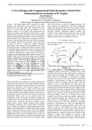
- 1. IJSRD - International Journal for Scientific Research & Development| Vol. 3, Issue 10, 2015 | ISSN (online): 2321-0613 All rights reserved by www.ijsrd.com 633 A Novel Design and Computational Fluid Dynamics of Swirl Flow Enhancing Device in Intake of IC Engine Jayakrishnan.S Assistant Professor Department of Automobile Technology Nehru College of Engineering and Research Centre, Thrissur, Kerala Abstract— The present paper work is directed to a device located at the intake port at the junction of the intake manifold and the engine head. This location allows the device to be used with any type of carburetor or fuel injection system. It is the object of the present device to utilize at least three fixed, helically twisted blades to impart additional swirl mixing of the fuel/air mixture. This fuel/air mixture has already been pre-heated by its travel through the intake manifold. The "violent swirl" created by the device provides a more uniform fuel/air mixture, thereby causing a more complete and efficient combustion. The overall result of using the device is better gas mileage, increased performance, easier starting, and less pollution. The object of the project work to improve the fuel/air mixture of the fuel injected engines, preventing valves from being burned or eroded by clogged injectors. As a result of forcing the air to enter the intake port in a high velocity swirl, there is disruption of any direct fuel streams upon the head of the cylinder intake valve which occur as a result of clogged injectors. Another object of the project work is to provide a device that improves the homogeneity of the fuel/air mixture delivered by the carburetor to the cylinders of an internal combustion engine with little or no obstruction in the mixture flow resulting in no starving of the engine. Another object to deliver the fuel/air mixture to the center of the cylinder for a uniform flame front. The swirling mixture delivered by the present invention results in cleaner, more- efficient combustion. Key words: Internal Combustion Engine, Swirl, CATIA V5, Computational Fluid Dynamics (CFD) I. INTRODUCTION The present paper work is directed to a device located at the intake port at the junction of the intake manifold and the engine head. This location allows the device to be used with any type of carburetor or fuel injection system. It is the object of the present device to utilize at least three fixed, helically twisted blades to impart additional swirl mixing of the fuel/air mixture. The strategic location of the device in the flow path creates the violent swirl of the fuel/air mixture immediately before and as the mixture enters the combustion cylinder. This fuel/air mixture has already been pre-heated by its travel through the intake manifold. The "violent swirl" created by the device provides a more uniform fuel/air mixture, thereby causing a more complete and efficient combustion. The overall result of using the device is better gas mileage, increased performance, easier starting, and less pollution. It is another object of the project work to improve the fuel/air mixture of the fuel injected engines, preventing valves from being burned or eroded by clogged injectors. As a result of forcing the air to enter the intake port in a high velocity swirl, there is disruption of any direct fuel streams upon the head of the cylinder intake valve which occur as a result of clogged injectors. The device requires no modification to the basic combustion engine. The configuration and size of the invention will vary according to the type of intake opening found in the various four-cycle internal combustion engines, whether one cylinder or more, whether in-line, opposed, V-type, or radial engines. In this work for design CATIA V5 and for analyzing CFD software for analyzing swirl flow. II. GEOMETRY DESIGN The schematic diagram of the swirl device usage is as shown in Figure1. Fig. 1: Schematic Diagram of the Airflow Including the Swirl Device Wing structure of air swirling device for internal combustion engine, which has a swirling device body mounted in the air flow system of the engine, a plurality of wings mounted slantingly and radically on said swirling device body for accelerating or increasing an airflow revolution, and one or more slits formed on prescribed positions of said plurality of wings for suppressing the formation of eddy in a negative pressure zone on the rear surface of each of said plurality of wings, said wing structure comprising: a plurality of auxiliary wings protrudly provided to the outside with reference to the surface of each of said plurality of wings, so that the airflow collided against the surface of each of said plurality of wings goes straight ahead. A wing structure of air swirling device for internal combustion engine, which has a swirling device body mounted in the air flow system of the engine, a plurality of wings mounted slantingly and radically on said swirling device body for accelerating or increasing an airflow revolution, and one or more slits formed on prescribed positions of said plurality of wings for suppressing the formation of eddy in a negative pressure zone on the rear surface of each of said plurality of wings, said wing structure comprising: one or more airflow holes formed at prescribed positions for reducing airflow resistance due to eddy generated at a negative pressure zone of each of said plurality of wings; and a plurality of auxiliary wings protrudly provided to the outside with reference to the surface of each of said plurality of wings, so that the airflow
- 2. A Novel Design and Computational Fluid Dynamics of Swirl Flow Enhancing Device in Intake of IC Engine (IJSRD/Vol. 3/Issue 10/2015/135) All rights reserved by www.ijsrd.com 634 collided against the surface of each of said wings go straight ahead. A wing structure of an air swirling device used in an air cleaner or an air duct of an internal combustion engine, which induces a swirl action of air filtered through an air cleaner of a spark ignition internal combustion engine of a carburetor or fuel injection type, a diesel engine, and so on. The wing structure of the swirling device introduces airflows into a combustion chamber of the engine, which is effective in reducing resistance due to negative pressure and eddy formed on the wings in the air swirling device, thereby improving processibility of the wings and increasing the amount of air flow and the speed of air flow in the combustion chamber. Fig. 2: Swirl Enhancing Device with Inlet Manifold III. EQUATIONS USED BP = (2×π×N×T)/60 Kw TFC = (density of petrol × volume)/time in sec. Kg/hr SFC= TFC/BP Kg/Kwhr BTF= ((BP×3600)/ (TFC×CV) ×100 % ITE = ((IP×3600)/ (TFC×Cv)) ×100 % (Calorific Value, Cv of petrol = 44835 KJ/Kg) IP= BP+FP IV. EXPERIMENTAL SETUP A. Test Rig Specifications: 1) Engine: Four Cylinder Four Stroke vertical water cooled variable speed petrol engine. ‘PAL’ make .the engine is provided with clutch plate, cover assembly Bell housing, accelerator control, self start motor, dynamo, battery ignition switch, HT coil, cutout, solenoid switch etc. Bore: 73mm Stroke: 70mm Compression Ratio: 9:1 Loading device: Froude’s dynamometer Flow rate: 300 lpm Torque Arm Length: 410mm Fuel arrangement: 3-way clock connecting tube. Air intake measurement: Air intake reservoir with orifice plate and differential manometer. Multi-channel Digital Temperature Indicator to measure the temperature at various points. A sensor with digital panel: to indicate the RPM. V. RESULTS & DISCUSSION The device enhances the turbulence and hence results in better air-fuel mixing process among all the configurations of diesel engine. As a result, the thermal efficiency is increased and SFC and soot emission are reduced. It can be concluded that MM8 is the best trade-off between performance and emissions. Based on this investigation, the following conclusions are drawn: More power output is derived from the same given charge. Lesser emission due to far more complete combustion is provided and lesser carbon deposits in the combustion chamber, piston crown and exhaust system occur due to controlled complete combustion. There is no pinging or detonation or auto ignition due to reduced temperature in the combustion chamber and no residue of unburnt fuel. There is better fuel economy due to improved and complete combustion. A. Simulation Results: Fig. 3: Simulation Result with Out Device Fig. 4: Simulation Result with Device 1 Fig. 5: Simulation Result with Device 2 Fig. 6: Simulation Result with Device 3
- 3. A Novel Design and Computational Fluid Dynamics of Swirl Flow Enhancing Device in Intake of IC Engine (IJSRD/Vol. 3/Issue 10/2015/135) All rights reserved by www.ijsrd.com 635 Simulation with Engine Speed 1500 rpm the swirl device is simulated to detail the air flows. If the blade is taken out from the swirl device, the result shows that the intake manifold will not create a swirl flow before the mixtures enter the cylinder. The intake mixture will flow straight following the shape of the intake manifold. The simulation results of the swirl device are shown in Figure 2 shows that the air motion is straight at the inlet and change direction following the blade angle when the flow reaches the blades. It is because the blades act as guide vanes to guide the flow to change direction before flow through the blades and the swirl motion of the intake mixture created. Based on the simulation results, the following conclusions are drawn concerning the swirl created. Swirl will be generated after flow through the swirl device. The swirl device will increase significantly the swirl ratio when smaller blade angle used in the swirl device. VI. CONCLUSION Based on the simulation results, the following conclusions are drawn concerning the swirl created. Swirl will be generated after flow through the swirl device. The swirl device will increase significantly the swirl ratio when smaller blade angle used in the swirl device. And as per the experiment slight change in performance is occurred. By improving the existing design can create device without any frictional loss and By varying the design and number of blades we can reduce the eddy generation at negative pressure zone of the rear surface of the blades. Thus the carbon monoxide (CO) levels can be reduced up to about 17% at engine idle speed, the engine power can be increased up to about 11%, fuel economy can be improved to about 6%, and knocking of the engine can be reduced up to about 5%. ACKNOWLEDGEMENTS The author is grateful to the Centre for Research in Engineering design, Green Manufacturing and Computing (CRDGC), Department of mechanical Engineering, Nehru College of Engineering and Research Centre for facilitating this work. REFERENCES [1] Ballaney P. L. 1965. Thermal Engineering, Khanna Publishers. [2] Heywood J. B. 2002. Internal Combustion Engine Fundamental, Mcgraw Hill. [3] Swirl Device Characterstic Analysis In Intake Manifold Rosli Abu Bakar, Azhar Abdul Aziz, Chin Kok Leong, Mohd Fadzil Abd Rahim & Devarajan Ramasamy. [4] Automotive Development Center, Universiti Teknologi Malaysia (Utm). [5] Whitelaw J. H., Xu H. M. 1995. Cyclic Variations In A Lean-Burn Spark Ignition Engine Without And With Swirl, Sae Paper 950683. [6] Wing Structure of Air Swirling Device For Internal Combustion Engine Patent No: 6041753. [7] The Effect Of Swirl On Air / Fuel Mixing In A 4 Valve Gdi Engine Aeronautical And Automotive Engineering, Lough Borough University, Leicestershire, Uk (Ilass – Europe 2010, 23rd Annual Conference On Liquid Atomization And Spray Systems, Brno, Czech Republic, September 2010). [8] J.H. Ferziger and M. Peric, Computational Methods for Fluid Dynamics Springer, 1996. [9] P.Wesseling, Principles of Computational Fluid Dynamics. Springer,2001. APPENDIX BP Brake power TFC Total Fuel Consumption SFC Specific Fuel Consumption IP Indicated Power ITF Indicated Thermal Efficiency BTP Brake Thermal Efficiency