This document presents an interactive computation tree logic (CTL) model checker developed using a client/server architecture, enabling scalable and efficient verification of reactive systems. The tool leverages web services to address the challenges of state explosion and computational resources, and incorporates a graphical interface for model design. Experimental results indicate its effectiveness in handling large systems and improving the applicability of model checking in software design.
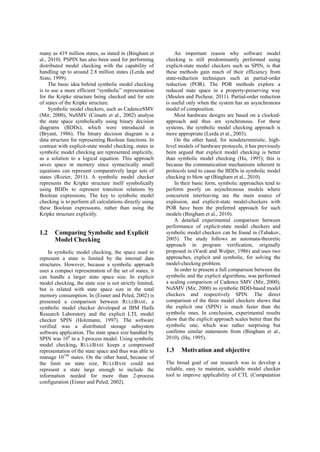
![model M (where are defined the sets S, Rel, and P)
and a formula , and provides as output the
denotation of – the set of states where the formula
is satisfied, using the following general algorithm:
assign atomic propositions by labelling
function P;
handle Boolean operators by standard set
operations;
handle temporal operators AX, EX by
computing pre-images using expressions
given in (1);
handle temporal operators AG, EG, AF, EF,
AU, EU by applying rules described in table
1, until a fixpoint is reached.
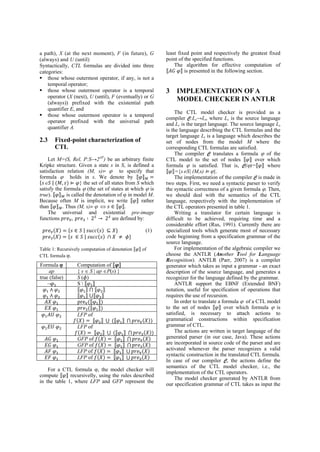
The algorithm for computing ⟦ ⟧ is
presented in figure 1 (Clarke et al., 1996).
For the formal specification of the AG operator
given in figure 1, the corresponding action
included in our ANTLR grammar of CTL language
is detailed in figure 2.
Z:=; Z':= ⟦ ⟧;
while (ZZ') do
Z:=Z';
Z':=Z' ∀ ;
endwhile
⟦ AG φ ⟧:=Z';
Figure 1: Formal definition of the set expression ⟦ ⟧.
private HashSet PreAll(HashSet Z) {
HashSet rez = new HashSet();
for (Node n1 : model) {
Iterator<Edge> it =
n1.getLeavingEdgeIterator();
HashSet succ = new HashSet();
while (it.hasNext()) {
Edge e = it.next();
Node n2 = e.getTargetNode();
succ.add(n2.getIndex());
}
if (Z.containsAll(succ)) {
rez.add(n1.getIndex());
}
}
return rez;
}
ctlFormula returns [HashSet set]
@init { }
: 'ag' e=implExpr {
HashSet rez = new HashSet();
HashSet rez1 = new HashSet($e.set);
while (!rez.equals(rez1)) {
rez.clear();
rez.addAll(rez1);
HashSet tmp = PreAll(rez1);
rez1.retainAll(tmp);
}
$set = rez1;
}
Figure 2: Implementation of the AG operator in ANTLR.
Analogue were implemented all CTL temporal
operators.
For efficient representation of CTL models, our
tool is based on SingleGraph class from
GraphStream package (GraphStream, 2012).
4 EMBEDDING THE CTL
MODEL CHECKER INTO A
WEB SERVICE
We choose to publish our implementation of
CTL model checker as a Web service in order to
utilize the combined resources of distributed
computers and to bring advantages of distributed
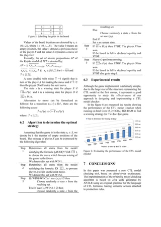
verification to various clients over the Web. As we
can see from the figure 3, the transport protocol
(HTTP) used by the Web Service enables clients to
invoke its methods through firewalls.
The architecture of the Web service
implementation is represented in figure 3.
Figure 3: The architecture of the ATL model checker Web
Service.
The Web service will receive from a client the
XML representation of a CTL model S and a CTL
formula to be verified. The original form of the
CTL model S is then reconstructed and passed to the
algebraic compiler C generated by ANTLR using
our CTL extended grammar. For a syntactically
correct formula , the compiler will return as result](https://image.slidesharecdn.com/adistributedctlmodelchecker-141022123452-conversion-gate02/85/A-Distributed-CTL-Model-Checker-5-320.jpg)


![谷歌留痕技术 [ 𝙩𝙤𝙥 𝟮𝟯𝟯. 𝙘 𝙤𝙢 ]](https://cdn.slidesharecdn.com/ss_thumbnails/top233-260130174328-3833018c-thumbnail.jpg?width=640&height=640&fit=bounds)


