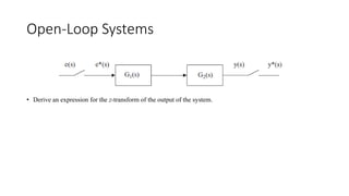
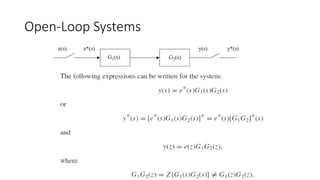
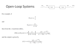
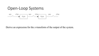
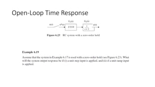
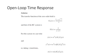
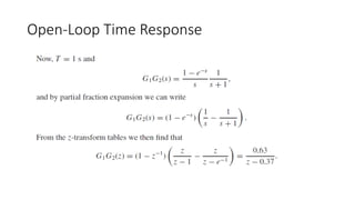
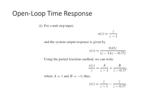
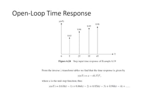
The document discusses pulse transfer functions and open-loop systems in digital control. It defines the pulse transfer function as the ratio of the z-transform of the sampled output to the input at sampling instants, emphasizing that sampling an already sampled signal has no further effect. Additionally, it covers deriving expressions for the z-transform of the output and obtaining the open-loop time response through inverse z-transforms for systems like RC circuits.

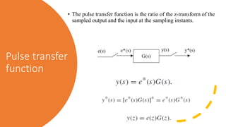
![Pulse transfer function
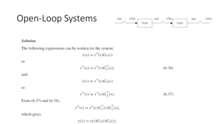
• If at least one of the continuous functions has been sampled, then the z-transform of the product is equal to the
product of the z-transforms of each function (note that [e*(s)]* = [e*(s)], since sampling an already sampled
signal has no further effect).
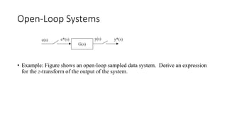
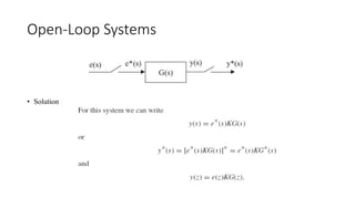
• G(z) is the transfer function between the sampled input and the output at the sampling instants and is called
the pulse transfer function.](https://image.slidesharecdn.com/pulsetransferfunctionandmanipulationofblockdiagramss121-240509154643-0f6642de/85/_PULSE_TRANSFER_FUNCTION_AND_MANIPULATION_OF_BLOCK_DIAGRAMS_s1_21-pdf-3-320.jpg)


![AUTONOMOUA_ROBOTICS_Week333333_5[1].pptx](https://cdn.slidesharecdn.com/ss_thumbnails/autonomouaroboticsweek51-240729082503-8b068bef-thumbnail.jpg?width=640&height=640&fit=bounds)


