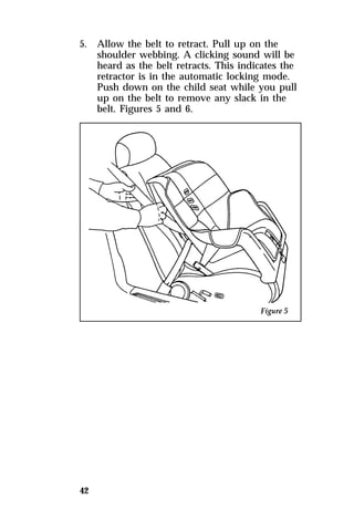
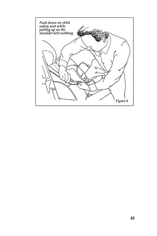
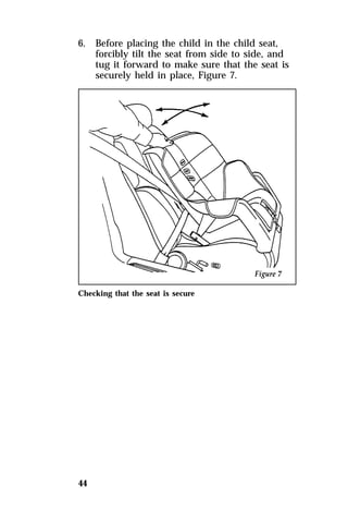
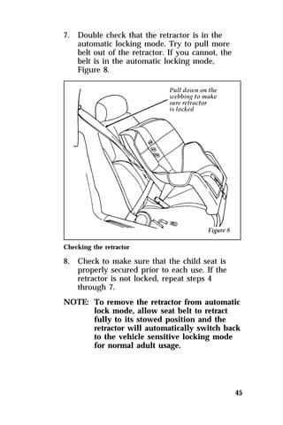
This document provides an overview and instructions for various features in a Ford Sable owner's manual. It includes sections on safety restraints like seat belts, starting the vehicle, instrument controls, driving instructions, maintenance, and more. The introduction discusses Ford's commitment to quality and customer satisfaction. It also notes that some information may not apply depending on options for the specific vehicle.


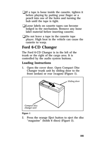
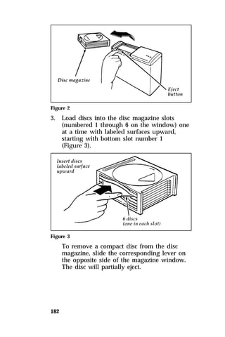
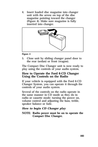
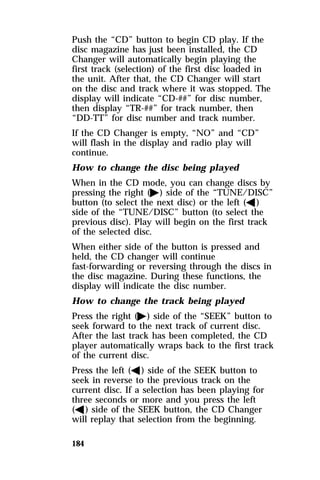
![NOTE: If your speed increases above your set
122
speed while driving in j (Overdrive)
on a downhill grade, you may want to
shift to D (Drive) to reduce vehicle
speed (or, turn j [Overdrive] off by
depressing the O/D OFF switch on the
gearshift lever). The speed control
cannot reduce the vehicle speed if it
goes above your set speed on a
downhill grade. For the best fuel
economy during normal driving
conditions, leave the gearshift in j
(Overdrive), or resume as soon as
practical.
RWARNING
To keep control of your vehicle, do
not use the speed control in heavy
traffic or on roads that are winding,
slippery, or unpaved.
Accelerating With the Speed Control
Operating
You can use the accelerator pedal to speed up
momentarily. When you take your foot off the
accelerator, the vehicle will return to the set
speed.
NOTE: When driving in hilly terrain, at high
altitudes, or when pulling a trailer, you
may want to drive in D (Drive) (or
turn j [Overdrive] off by depressing
the O/D OFF switch). This will
improve speed control performance.](https://image.slidesharecdn.com/96sable-140829162841-phpapp01/85/96-sable-149-320.jpg)
![[AS10350(ALL)08/95]](https://image.slidesharecdn.com/96sable-140829162841-phpapp01/85/96-sable-196-320.jpg)

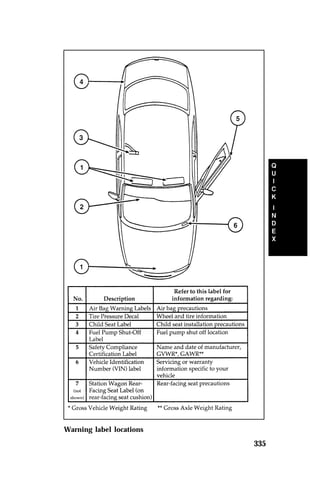
![NOTE: When adding accessories, equipment,
passengers, and luggage to your
vehicle, do not exceed the total weight
capacity of the vehicle or of the front
or rear axle (GVWR, GAWR as shown
on the Safety Compliance Certification
Label). Consult your dealer for specific
weight information.
249
NOTE: The Federal Communications
Commission (FCC) regulates the use of
mobile communications systems —
such as two-way radios, telephones,
and theft alarms — that are equipped
with radio transmitters. Any such
equipment installed in your vehicle
should comply with FCC regulation
and should be installed only by a
qualified technician.
NOTE: Mobile communications systems may
harm the operation of your vehicle,
particularly if they are not properly
designed for automotive use or are not
properly installed. For example, when
operated, such systems may cause the
engine to stumble or stall. In addition,
such systems may themselves be
damaged or their operation affected by
operating your vehicle. (Citizens band
[CB] transceivers, garage door openers,
and other transmitters whose power
output is 5 watts or less will not
ordinarily affect your vehicle’s
operation.)
NOTE: Because we have no control over the
installation, design, or manufacture of
such systems, Ford cannot assume
responsibility for any adverse effects or
damage that may result if you use this
equipment.](https://image.slidesharecdn.com/96sable-140829162841-phpapp01/85/96-sable-276-320.jpg)

![264
RWARNING
The fuel system may be under
pressure. If the fuel cap is venting
vapor or if you hear a hissing sound,
wait until it stops before completely
removing the cap. Otherwise, fuel
may spray out and injure you or
others.
2. Make sure that you pump unleaded fuel and
put the nozzle all the way inside the fuel
filler pipe.
NOTE: To help reduce early nozzle shutoffs
and fuel spillage, park your vehicle so
that the fuel filler door is not
downhill. Do not tilt or turn the nozzle
upside down when filling. Avoid
excessively fast fuel dispensing rates
(over 10 gallons [38 liters] per minute).
3. If you spill any fuel on the body of your
vehicle, clean it off immediately. The fuel
may dull or soften the paint if you do not
wash it off.
4. To replace the fuel cap, align the tabs on the
cap with the notches on the filler pipe. Turn
it clockwise until it stops.
5. Push the fuel door closed.
If the Service Engine Soon warning light comes
on and stays on when you start the engine, the
fuel cap may not be properly seated. Turn off
the engine, remove the fuel cap and replace it,
being careful to align the cap properly. For more
information, see Warning lights in the Index.](https://image.slidesharecdn.com/96sable-140829162841-phpapp01/85/96-sable-291-320.jpg)
![279
RWARNING
Failure to follow these instructions
could result in serious personal
injury from hot engine coolant or
steam blowout and/or damage to the
engine cooling system or engine.
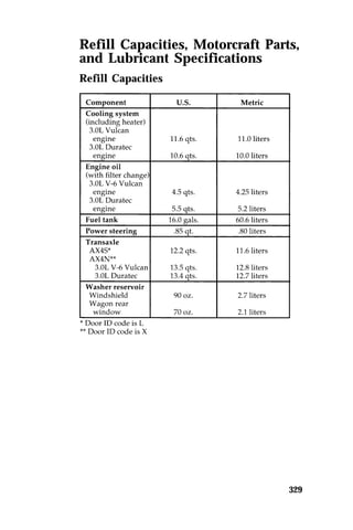
To find out how much engine coolant mixture
your vehicle’s coolant system can hold, see Refill
capacities for fluids in the Index.
Add engine coolant only to the coolant
reservoir. If the coolant level is low, add to the
reservoir a 50/50 mixture of water and the type
of engine coolant that Ford specifies. You may
add water by itself only in an emergency, but
you should replace it with a 50/50 mixture as
soon as possible.
Ford Premium Cooling System Fluid is an
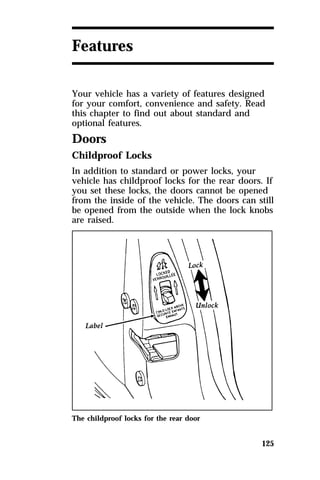
optimized formula that will protect all metal and
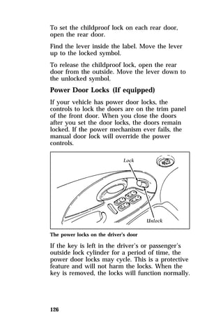
rubber elastomers used in Ford engines for four
years or 50,000 miles (80,000 km). It is not
necessary and not recommended to use
supplemental coolant additives in your vehicle.
These additives may harm your engine cooling
system. Follow the recommended service interval
for changing your engine coolant.
NOTE: When you change or add engine
coolant, it is important to maintain
your engine coolant concentration
between 40% (-11°F [-24°C]) and 60%
(-62°F [-52°C]), depending on your local
climate conditions. Below 40% you will
lose freeze protection and above 60%
your engine may overheat on a warm
day.](https://image.slidesharecdn.com/96sable-140829162841-phpapp01/85/96-sable-306-320.jpg)
![284
RWARNING
Do not add the windshield washer
fluid to the engine coolant reservoir.
This could damage your cooling
system. Do not add engine coolant to
the washer fluid reservoir. This could
damage your wiper/washer system.
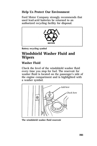
Use specially formulated windshield washer
fluid rather than plain water, because specially
formulated washer fluids contain additives that
dissolve road grime. For safety reasons, washer
fluids containing an appropriate antifreeze such
as methanol should be used in freezing weather
(temperatures below 32°F [0°C]). State or local
regulations on Volatile Organic Compounds
(VOC’s) may restrict use of the most common
antifreeze, methanol. Washer fluids containing
non-methanol antifreeze agents should be used
only if they provide cold weather protection
without damaging the vehicle’s paint finish,
wiper blades, and windshield washer system.
RWARNING
Washer solution contains methanol
which is poisonous. Observe all
warnings indicated on label of
washer solution.
Checking the washer fluid for the
liftgate (If equipped)
If your wagon has a rear window wiper, check
the reservoir for its washer fluid regularly. This
is not the same reservoir that your windshield
wipers use. The opening for this reservoir is on
the right side of the liftgate opening, below the
tail lamp. Refill this reservoir with the same](https://image.slidesharecdn.com/96sable-140829162841-phpapp01/85/96-sable-311-320.jpg)