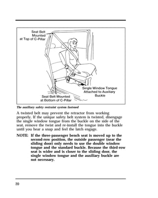
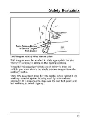
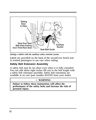
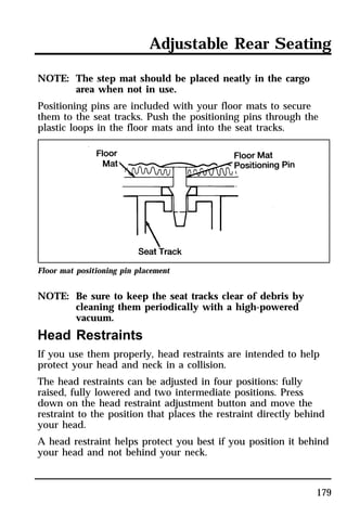
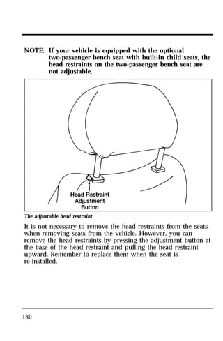
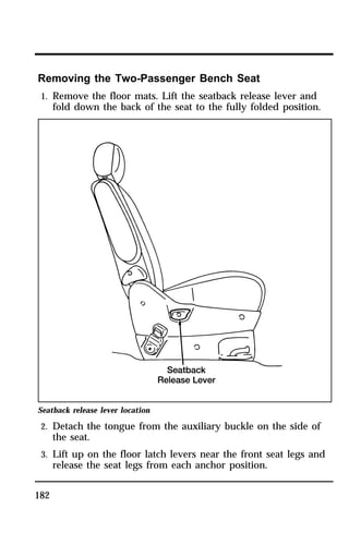
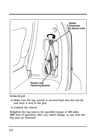
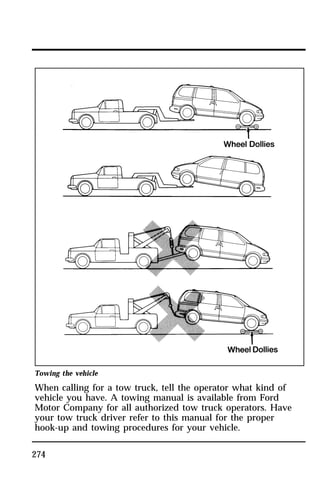
This document provides an overview and table of contents for an owner's manual for the Ford Villager. It includes sections on safety restraints, starting the vehicle, warning lights and gauges, instrument panel controls, steering column controls, features, adjustable rear seating, electronic sound systems, driving the vehicle, roadside emergencies, customer assistance, reporting safety defects, accessories, and servicing the vehicle. The introduction discusses the purpose of the owner's manual and provides guidance on how to use it.

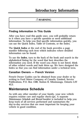
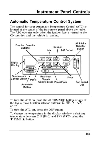
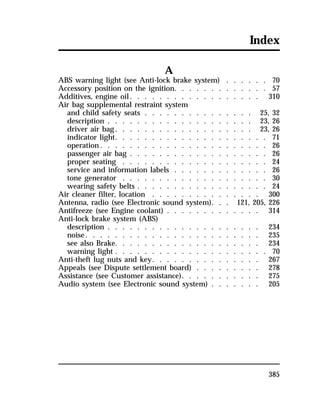
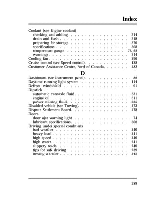
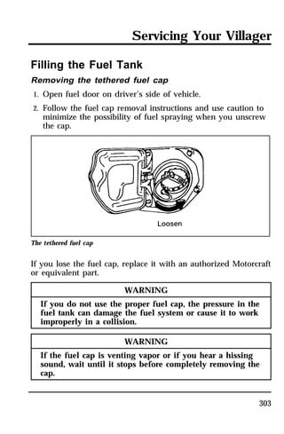
![The ATC maintains the temperature you select and
automatically controls the airflow for your comfort. It also
allows you to override the automatic operation of airflow and
fan speed with manual function selector buttons and the fan
speed dial.
When you select the AUTOMATIC button, the system
determines airflow location and fan speed automatically. It also
automatically determines whether you will be receiving fresh
outside airflow, recirculated interior airflow, or a combination of
both. You can manually override the airflow source (outside or
recirculated air) and airflow location by selecting one of the
function selector buttons. You can also manually override the
fan speed by rotating the fan speed dial.
Whether you operate in the AUTOMATIC mode or manually
override the AUTOMATIC mode settings, the ATC will continue
to maintain the air temperature you have selected. However, if
you choose to manually override the airflow location by
selecting one of the function selector buttons, you will also need
to select the A/C button if you desire cool air-conditioned air.
(Your ATC automatically operates the air conditioning [if
required] when you are in the AUTOMATIC mode without
illuminating the A/C button, but the system requires you to
manually select the A/C button if you desire A/C operation
when you manually override airflow location.)
If you want continuous maximum cooling, push the N side of
the TEMP button until 60°F (16°C) shows in the display
window. The ATC will cool at its maximum level and disregard
the 60°F (16°C) setting until a warmer temperature is selected. If
you want continuous maximum heating, push the M side of the
TEMP button until 90°F (32°C) shows in the display window.
The ATC will provide maximum heat regardless of the 90°F
(32°C) setting until a cooler temperature is selected.
104](https://image.slidesharecdn.com/96villager-140829162849-phpapp01/85/96villager-104-320.jpg)
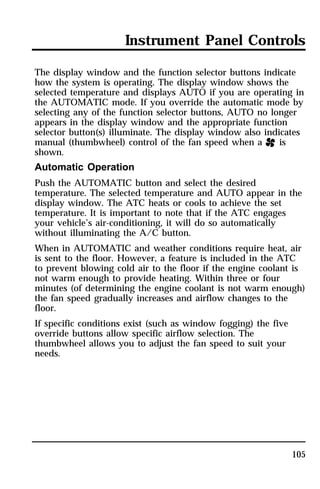
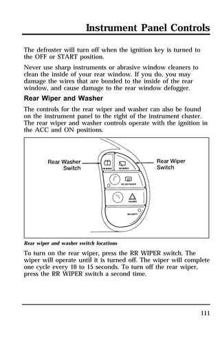
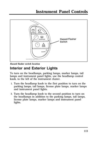
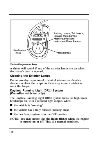
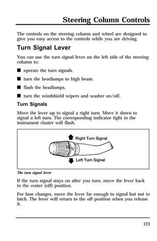
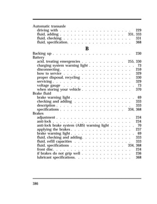
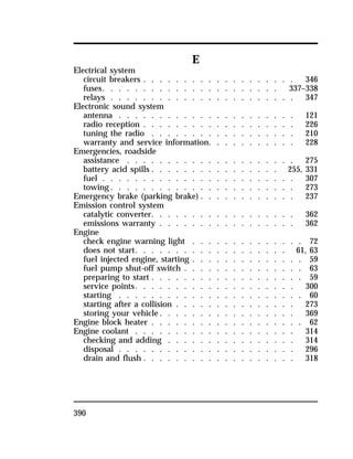
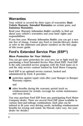
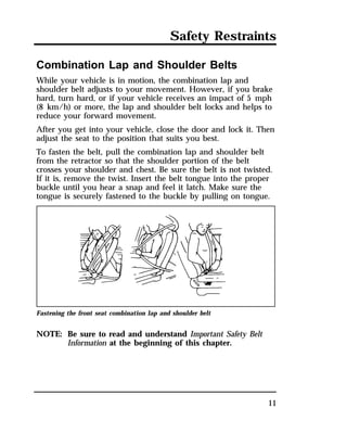
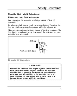
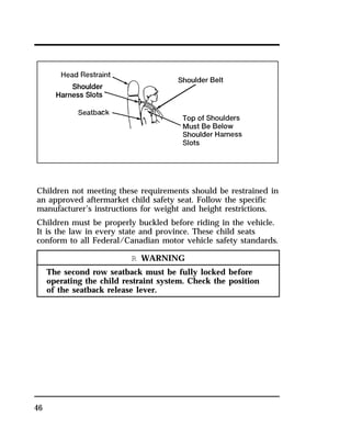
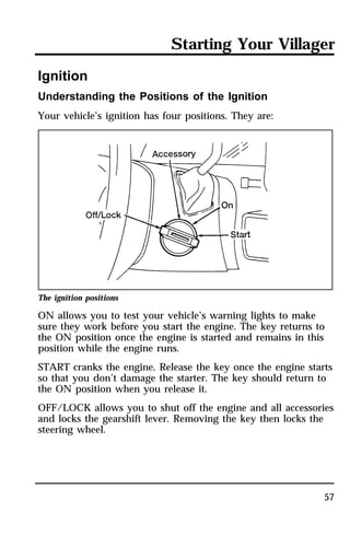
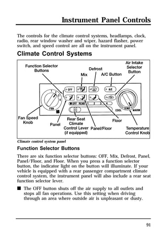
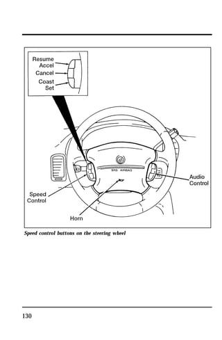
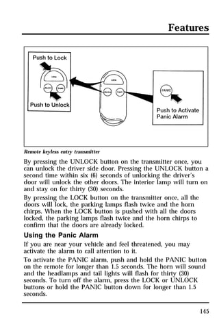
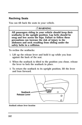
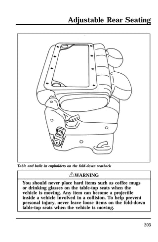
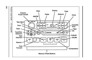
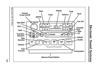
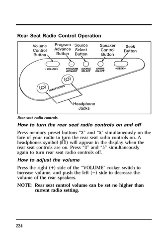
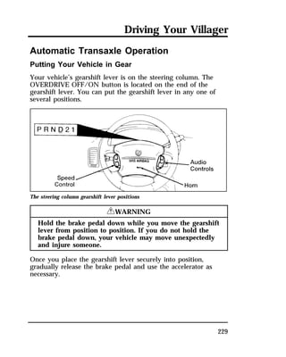
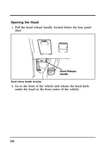
![Steering Column Controls
Speed control main switch location
Setting the Speed Control
To set the speed control, accelerate your vehicle to the desired
speed (at least 30 mph [48 km/h]), push and release the
COAST/SET button on the left side of the steering wheel. The
CRUISE light in the instrument cluster will come on. Take your
foot off the accelerator pedal. Your vehicle will maintain the set
speed.
129](https://image.slidesharecdn.com/96villager-140829162849-phpapp01/85/96villager-128-320.jpg)
![NOTE: Mobile communication systems, particularly if not
290
properly installed, may adversely affect the operation
of the vehicle. For example, such systems, when
operated, may cause the engine to stumble or stall. In
addition, such systems may themselves be damaged,
or their operation affected, by the operation of the
vehicle. (Citizens band [CB] transceivers, garage door
openers, and other transmitters whose power output is
5 watts or less, ordinarily will not affect vehicle
operation.)
NOTE: Because Ford has no control over the operation or
manufacture of such systems or their installation, Ford
cannot assume responsibility for any adverse effects or
damage if this equipment is used.](https://image.slidesharecdn.com/96villager-140829162849-phpapp01/85/96villager-285-320.jpg)
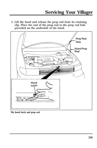
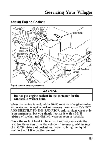
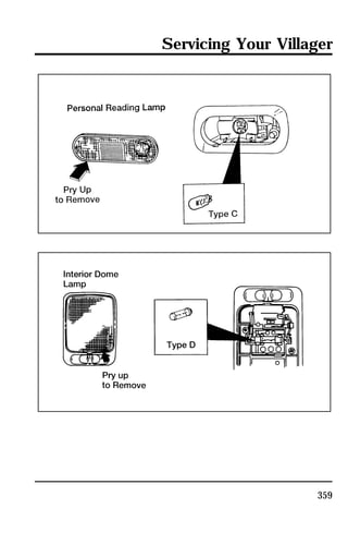
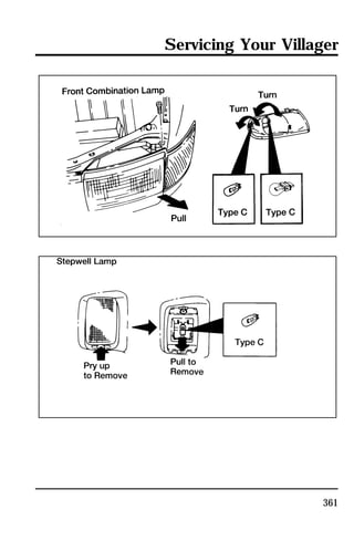
![Servicing Your Villager
Recycled engine coolant
Ford Motor Company recommends that Ford and
Lincoln-Mercury dealers use recycled engine coolant produced
by Ford-approved processes. Not all coolant recycling processes
produce coolant which meets Ford specification ESE-M97B44-A,
and use of such coolant may harm engine and cooling system
components.
Always dispose of used automotive fluids in a responsible
manner. Follow your community’s regulations and standards for
recycling and disposing of automotive fluids.
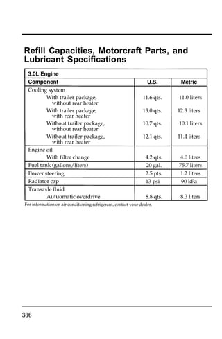
Coolant refill capacity
To find out how much fluid your vehicle’s cooling system can
hold, see Refill capacities for fluids in the Index.
Have your dealer check the engine cooling system for leaks if
you have to add more than a quart (liter) of engine coolant per
month.
Severe winter climate
If you drive in extremely cold climates (less than -34°F [-36°C]),
it may be necessary to increase the coolant concentration above
50%. Refer to the chart on the coolant container to ensure the
coolant concentration in your vehicle is such that the coolant
will not freeze at the temperature level in which you drive
during winter months. Never increase the engine coolant
concentration above 60%. Leave a 50/50 mixture of engine
coolant and water in your vehicle year-round in non-extreme
climates.
Checking hoses
Inspect all engine and heater system hoses for deterioration,
leaks and loose clamps before adding or replacing engine
coolant. Make whatever repairs or replacements are necessary
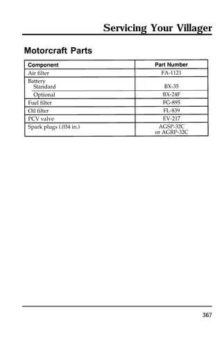
using Motorcraft parts or their equivalents.
317](https://image.slidesharecdn.com/96villager-140829162849-phpapp01/85/96villager-311-320.jpg)
![Use specially formulated windshield washer fluid rather than
plain water, because specially formulated washer fluids contain
additives that dissolve road grime. For safety reasons, washer
fluids containing an appropriate antifreeze such as methanol
should be used in freezing weather (temperatures below 32°F
[0°C]). State or local regulations on Volatile Organic Compounds
(VOC’s) may restrict use of the most common antifreeze,
methanol. Washer fluids containing non-methanol antifreeze
agents should be used only if they provide cold weather
protection without damaging the vehicle’s paint finish, wiper
blades, and windshield washer system.
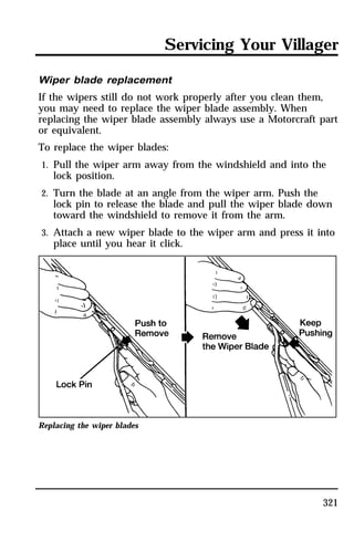
Wiper Blades
Check the windshield wiper blades at least twice a year. Also
check them whenever they seem less effective than usual.
Substances such as tree sap and some hot wax treatments used
by commercial car washes reduce the effectiveness of wiper
blades.
If the blades do not wipe properly, clean both the windshield
and the wiper blades. Use undiluted windshield washer solution
or a mild detergent. Rinse thoroughly with clear water. Do not
use fuel, kerosene, paint thinner, or other solvents to clean your
wiper blades. These will damage your blades.
To reach the wiper blades easily, turn the ignition switch to
ACCESSORY and turn your wipers on. Wait for them to reach a
vertical position and turn the ignition to OFF. Moving the
wipers manually may damage them.
320](https://image.slidesharecdn.com/96villager-140829162849-phpapp01/85/96villager-314-320.jpg)