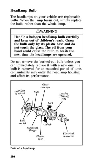
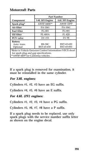
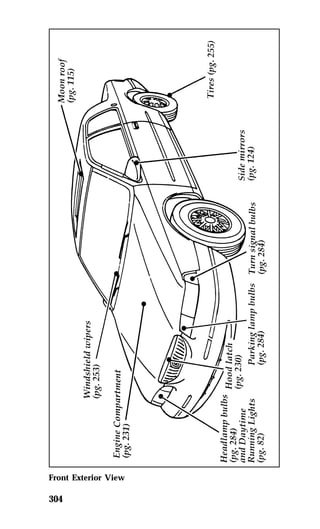
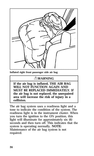
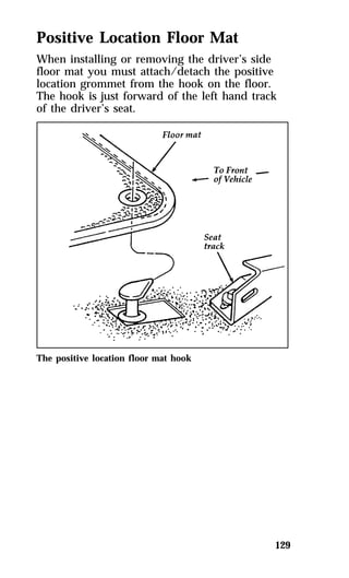
This document provides an overview of Ford's guiding principles for quality, customer focus, continuous improvement, employee involvement, partnerships, and integrity. It then discusses how to use the vehicle owner's guide, including safety information about wearing seatbelts, adjusting seatbelts, cleaning and maintaining the vehicle, and basic vehicle operation instructions. It emphasizes that seatbelts should be worn correctly to provide optimal safety.

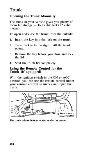

![NOTE: Mobile communications systems may
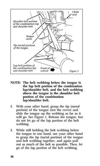
220
harm the operation of your vehicle,
particularly if they are not properly
designed for automotive use or are not
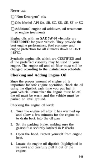
properly installed. For example, when
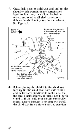
operated, such systems may cause the
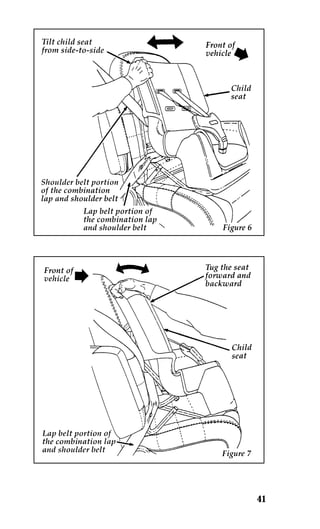
engine to stumble or stall. In addition,
such systems may themselves be
damaged or their operation affected by
operating your vehicle. (Citizens band
[CB] transceivers, garage door openers,
and other transmitters whose power
output is 5 watts or less will not
ordinarily affect your vehicle’s
operation.)
NOTE: Because we have no control over the
installation, design, or manufacture of
such systems, Ford cannot assume
responsibility for any adverse effects or
damage that may result if you use this
equipment.](https://image.slidesharecdn.com/96cougar-140829162811-phpapp01/85/96-cougar-219-320.jpg)
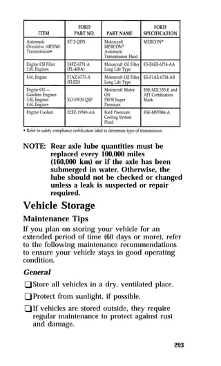
![Ford Premium Cooling System Fluid is an
optimized formula that will protect all metals
and rubber elastomers used in Ford engines for
four years or 50,000 miles (80,000 km). It is not
necessary and not recommended to use
supplemental coolant additives in your gasoline
powered vehicle. These additives may harm
your engine cooling system. Follow the
recommended service interval for changing your
engine coolant.
NOTE: When you change or add engine
coolant, it is important to maintain
your engine coolant concentration
between 40% (-11°F [-24°C]) and 60%
(-62°F [-52°C]), depending on your local
climate conditions. Below 40% you will
lose freeze protection and above 60%
your engine may overheat on a warm
day.
247
NOTE: The use of an improper coolant may
void your warranty for the engine
cooling system. Use only a premium
nationally recognized brand name
engine coolant. Do not use alcohol,
methanol antifreeze or engine coolant
mixed with alcohol or methanol
antifreeze. If you do not use the proper
coolant, the aluminum radiator on your
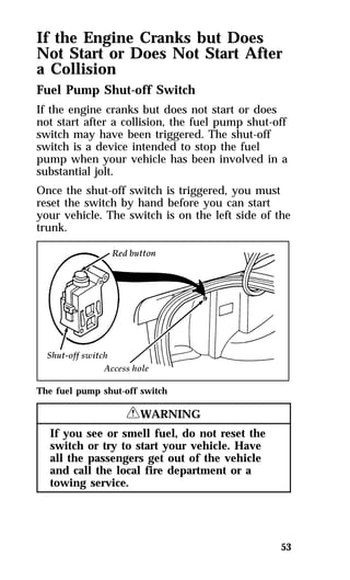
vehicle will corrode.
Ford Motor Company expressly authorizes the
Ford Rotunda engine coolant recycling process
and chemicals. Use only Ford Rotunda recycled
engine coolant or an equivalent recycled engine
coolant that is certified by the supplier to meet
Ford specification ESE-M97B44-A.](https://image.slidesharecdn.com/96cougar-140829162811-phpapp01/85/96-cougar-244-320.jpg)
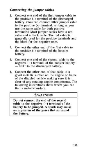
![Windshield Washer Fluid and
Wipers
Washer Fluid
Check the level of the windshield washer fluid
periodically, or when the optional lamp indicates
low fluid. The reservoir for washer fluid is
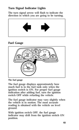
located on the driver’s side of the engine
compartment. Visual inspection can determine if
the washer fluid is adequate. Do not operate the
washer when the reservoir is empty.
253
The reservoir for the windshield washer fluid
RWARNING
Do not put windshield washer fluid in the
container for the engine coolant.
Use specially formulated windshield washer
fluid rather than plain water, because specially
formulated washer fluids contain additives that
dissolve road grime. For safety reasons, washer
fluids containing an appropriate antifreeze such
as methanol should be used in freezing weather
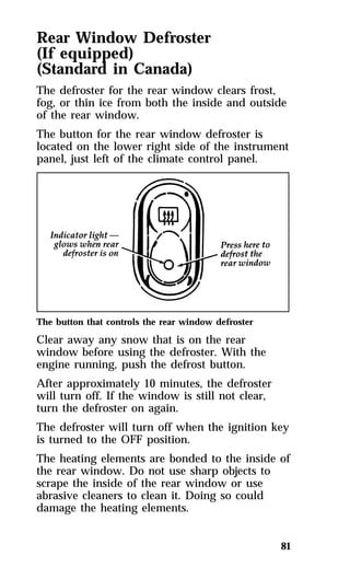
(temperatures below 32°F [0°C]). State or local
regulations on Volatile Organic Compounds
(VOC’s) may restrict use of the most common
antifreeze, methanol. Washer fluids containing](https://image.slidesharecdn.com/96cougar-140829162811-phpapp01/85/96-cougar-250-320.jpg)