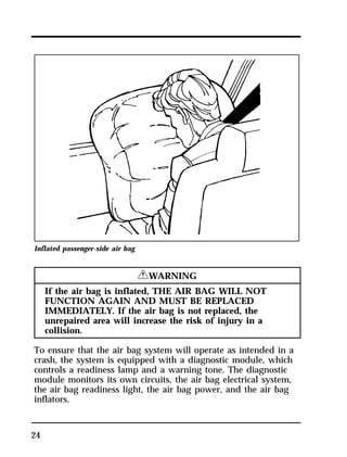
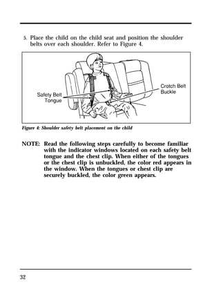
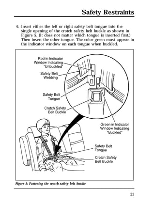
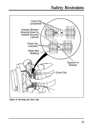
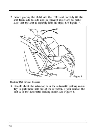
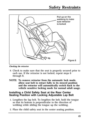
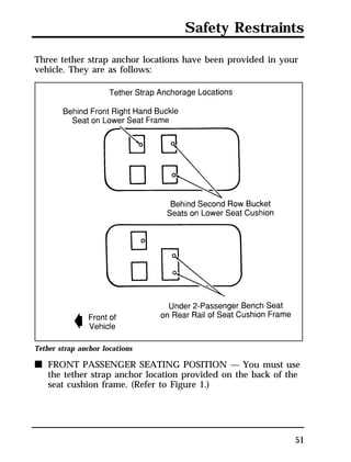
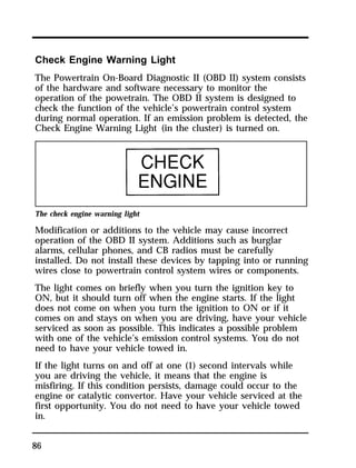
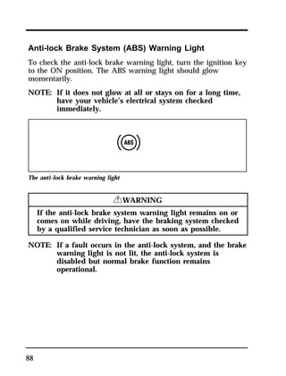
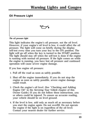
This document provides an overview of safety restraints and instructions for properly using safety belts in a Ford Windstar vehicle. It describes how safety belts should fit snugly across the hips and chest when worn correctly to provide optimal restraint in a collision. The document warns that safety belts must be used properly by all passengers, including pregnant women, to avoid greatly increasing the risk of injury.


![Accessories
297
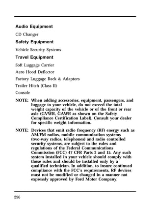
NOTE: Mobile communication systems, particularly if not
properly installed, may adversely affect the operation
of the vehicle. For example, such systems, when
operated, may cause the engine to stumble or stall. In
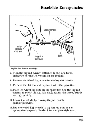
addition, such systems may themselves be damaged,
or their operation affected, by the operation of the
vehicle. (Citizens band [CB] transceivers, garage door
openers, and other transmitters whose power output is
5 watts or less, ordinarily will not affect vehicle
operation.)
NOTE: Because Ford has no control over the operation or
manufacture of such systems or their installation, Ford
cannot assume responsibility for any adverse effects or
damage if this equipment is used.](https://image.slidesharecdn.com/96windstar-140829162852-phpapp02/85/96windstar-297-320.jpg)
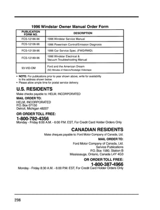
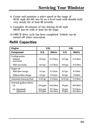
![additives in your gasoline powered vehicle. These additives may
harm your engine cooling system. Follow the recommended
service interval for changing your engine coolant.
NOTE: When adding to or changing your engine coolant, it is
322
important to maintain a coolant concentration between
40% (s11°F [s24°C]) and 60% (s62°F [s52°C])
depending on your local climate conditions. When
coolant concentration falls below 40%, you will lose
freeze protection; above 60%, your engine may
overheat on a warm day. If coolant concentration is
outside this range, you may lose corrosion and rust
protection for the metals in your engine cooling
system.
NOTE: Do not use an engine coolant that does not meet all
14 requirements of Ford specification ESE-M97B44-A.
The use of a coolant that does not meet the 14
requirements may void your warranty for the engine
cooling system. Use only a premium, nationally
recognized brand name engine coolant.
Ford Motor Company expressly authorizes the Ford Rotunda
engine coolant recycling process and chemicals. Use only Ford
Rotunda recycled engine coolant or an equivalent non-Ford
Rotunda recycled engine coolant that is certified by the supplier
to meet Ford specification ESE-M97B44-A.
NOTE: Always dispose of used automotive fluids in a
responsible manner. Follow your community’s
standards for disposing of these types of fluids. Call
your local recycling center to find out about recycling
automotive fluids.
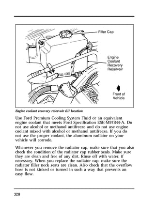
Leave the coolant in all year. Make sure that the coolant will
not freeze at the temperature level in which you usually drive
during winter months. Keep an engine coolant in your engine
that has a protection rating of at least s20°F (s29°C).](https://image.slidesharecdn.com/96windstar-140829162852-phpapp02/85/96windstar-322-320.jpg)
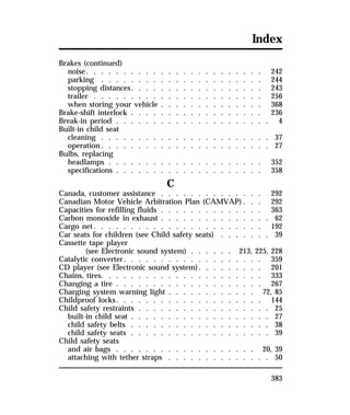
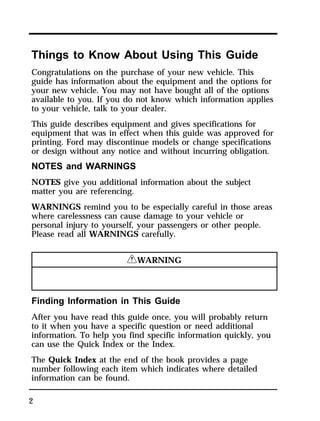
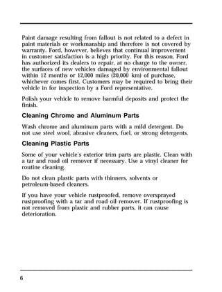
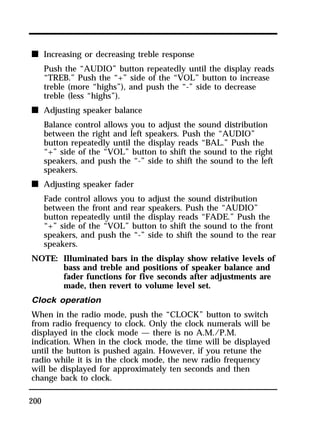
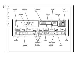
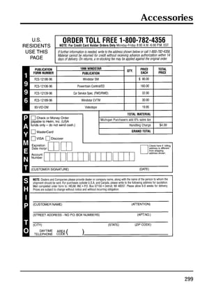
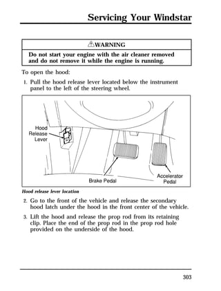
![Windshield washer fill location
Use specially formulated windshield washer fluid rather than
plain water, because specially formulated washer fluids contain
additives that dissolve road grime. For safety reasons, washer
fluids containing an appropriate antifreeze such as methanol
should be used in freezing weather (temperatures below 32°F
[0°C]). State or local regulations on Volatile Organic Compounds
(VOC’s) may restrict use of the most common antifreeze,
methanol. Washer fluids containing non-methanol antifreeze
agents should be used only if they provide cold weather
protection without damaging the vehicle’s paint finish, wiper
blades, and windshield washer system.
326
RWARNING
Washer solution contains methanol which is poisonous.
When adding windshield washer solution, be sure to observe all
warnings indicated on the washer solution container.](https://image.slidesharecdn.com/96windstar-140829162852-phpapp02/85/96windstar-326-320.jpg)