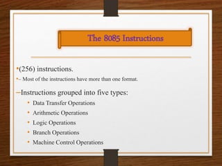
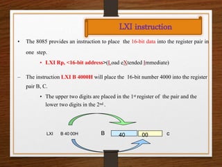
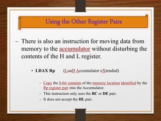
Introduction to 8085
Instructions
Presented by
SUDESHNA DEY
Asst.Professor (ECE)
Dream Institute of Technology
CONTENT:
NEXT
Introduction
Instruction
Data Format
PIN
Description
•(256) instructions.
•– Most of the instructions have more than one format.
–Instructions grouped into five types:
• Data Transfer Operations
• Arithmetic Operations
• Logic Operations
• Branch Operations
• Machine Control Operations
The 8085 Instructions
Instruction and Data Formats
• Each instruction has two parts.
– The first part is the task or operation to
be performed.
• This part is called the “opcode” (operation
code).
– The second part is the data to be operated
on
• Called the “operand”.
Data Transfer Operations
– These operations simply COPY the data from the
source to the destination.
– MOV, MVI, LDA, and STA
– They transfer:
• Data between registers.
• Data Byte to a register or memory location.
• Data between a memory location and a register.
• Data between an IO Device and the accumulator
The data in the source is not changed.
LXI instruction
• The 8085 provides an instruction to place the 16-bit data into the register pair in
one step.
• LXI Rp, <16-bit address>(Load eXtended Immediate)
– The instruction LXI B 4000H will place the 16-bit number 4000 into the register
pair B, C.
• The upper two digits are placed in the 1st register of the pair and the
lower two digits in the 2nd .
LXI B 40 00H B c
40 00
Memory “Register
• Most of the instructions of the 8085 can use a
memory location in place of a register.
– The memory location will become the “memory” register M.
• MOV M B
– copy the data from register B into a memory location.
– Which memory location?
• The memory location is identified by the contents
of the HL register pair.
– The 16-bit contents of the HL register pair are treated
as a 16-bit address and used to identify the memory
location.
Using the Other Register Pairs
– There is also an instruction for moving data from
memory to the accumulator without disturbing the
contents of the H and L register.
• LDAX Rp (LoaD Accumulator eXtended)
– Copy the 8-bit contents of the memory location identified by the
Rp register pair into the Accumulator.
– This instruction only uses the BC or DE pair.
– It does not accept the HL pair.
Address & Data Bus
Address & Data Bus
Address & Data Bus
Address & Data Bus
Address & Data Bus
8085-instruction.ppt

8085-instruction.ppt

  • 1.
    Introduction to 8085 Instructions Presentedby SUDESHNA DEY Asst.Professor (ECE) Dream Institute of Technology
  • 2.
  • 3.
    •(256) instructions. •– Mostof the instructions have more than one format. –Instructions grouped into five types: • Data Transfer Operations • Arithmetic Operations • Logic Operations • Branch Operations • Machine Control Operations The 8085 Instructions
  • 4.
    Instruction and DataFormats • Each instruction has two parts. – The first part is the task or operation to be performed. • This part is called the “opcode” (operation code). – The second part is the data to be operated on • Called the “operand”.
  • 5.
    Data Transfer Operations –These operations simply COPY the data from the source to the destination. – MOV, MVI, LDA, and STA – They transfer: • Data between registers. • Data Byte to a register or memory location. • Data between a memory location and a register. • Data between an IO Device and the accumulator The data in the source is not changed.
  • 6.
    LXI instruction • The8085 provides an instruction to place the 16-bit data into the register pair in one step. • LXI Rp, <16-bit address>(Load eXtended Immediate) – The instruction LXI B 4000H will place the 16-bit number 4000 into the register pair B, C. • The upper two digits are placed in the 1st register of the pair and the lower two digits in the 2nd . LXI B 40 00H B c 40 00
  • 7.
    Memory “Register • Mostof the instructions of the 8085 can use a memory location in place of a register. – The memory location will become the “memory” register M. • MOV M B – copy the data from register B into a memory location. – Which memory location? • The memory location is identified by the contents of the HL register pair. – The 16-bit contents of the HL register pair are treated as a 16-bit address and used to identify the memory location.
  • 8.
    Using the OtherRegister Pairs – There is also an instruction for moving data from memory to the accumulator without disturbing the contents of the H and L register. • LDAX Rp (LoaD Accumulator eXtended) – Copy the 8-bit contents of the memory location identified by the Rp register pair into the Accumulator. – This instruction only uses the BC or DE pair. – It does not accept the HL pair.
  • 9.
  • 10.
  • 11.
  • 12.
  • 13.