More Related Content

PPTX
FUNDAMENTAL OF VOLTAGE AND CURRENT 
PPT
Analog and Digital Multimeters 
PPTX
ELECTRICAL INSTRUMENTS 3.pptx 
DOCX

DOCX

PPT
Belajar multimeter analog dan digital di bidang elekktronika 
PPTX

PPTX
TOPIC 2.5- Testing Equipments.pptx Similar to 7.2.1 CETP Instructor PowerPoint Template.ppt

PPTX
Electrical Test Equipment and devices in Works 
PDF

PPT

PDF

PDF
Basicelectricalmeasuringinstruments 160111044802 
PPTX
Basic electrical measuring instruments 
PDF

PDF
How to Use a Multimeter - SparkFun Learn.pdf 
PPTX
Lect 4 analog meter PMMC.pptx 
PPTX

PPSX
Grade 10: Robotics Electrical Measurements Grade 10: Robotics Electrical Meas... 
PPTX

PPTX
4. Test instruments and their connections 
PPTX

PPT
How_to_use_a_Digital_Multi__meter___.ppt 
PPTX
How to use a digital multimeter 
PPT
Multimeter beee engg basic electronic en 
PPTX
Current and Voltage Measurement - Using a Multimeter 
PPT

PPTX
Eee 326 measurement and instrumentations Recently uploaded

PDF
Albert Pintoy - Specializing In Low-Latency 
PDF
Presentation-on-Energy-Transition-in-Bangladesh-Employment-and-Skills.pdf 
PPTX
Unit 1 Introduction to Information Technology in Business.pptx 
PPTX
MECCA Empire – Hotel Shuttle System for the 2026 FIFA World Cup 
PPTX
Best CMMS for IoT Integration: Real-Time Asset Intelligence & Smart Maintenan... 
PPTX
firewall Selection in production life pptx 
PPTX
TPM Metrics & Measurement: Drive Performance Excellence with TPM | MaintWiz 
PPTX
Vertical turbine pump explains installed in power plants 
PPTX
ISO 14224 Compliance & CMMS Software — A Comprehensive Guide for Reliable Mai... 
PPT
new Introduction to PACS.ppt Picture Archieving and communication and medicine 
PPTX
How to Create an Effective Monthly Maintenance Plan for Reliable Plant Operat... 
PPTX
Salesforce Bulk Connector V1 and V2 Deep Dive! 
PPTX
How to Select the Right CMMS Software for Your Organization — A Complete Buye... 
PPTX
Shutdown Maintenance Explained — Full Plant Turnaround & Best Practices with ... 
PPTX
Role of In Vitro and In Vivo Testing biomedical engineering 
PPTX
Revolutionizing Facilities Management with MaintWiz — AI CMMS for Smart FMaaS 
PDF
AI-Driven CTI for Business: Emerging Threats, Attack Strategies, and Defensiv... 
PPTX
22304_BCO_CO3_LO4_PPT MSBTE Building construction.pptx 
PDF
Human computer Interface ppt aUNIT 3.pdf 
PPTX
How to Implement Kaizen in Your Organization for Continuous Improvement Success 7.2.1 CETP Instructor PowerPoint Template.ppt
- 1.
7.2.1 Student Book © 2005 Propane Education & Research Council Page 1
7.2.1
Identifying Basic Meter and Hazard
Reducing Guidelines Used in
Measuring Electrical Quantities
The multimeter is a primary tool for the appliance service
technician. In this module, you will learn to:
1. Identify the operating principle of the basic analog meter
movement
2. Identify how to read a typical analog multimeter scale
3. Identify the operating principle and functions of a voltmeter
4. Identify the operating principle and functions of an ammeter
- 2.
7.2.1 Student Book © 2005 Propane Education & Research Council Page 1
5. Identify the operating principle and functions of an
ohmmeter
6. Identify the operating principle and functions of digital
multimeters (DMM)
7. Identify the operating principle and functions of clamp
meters
8. Identify principles of meter safety and meter categories
- 3.
7.2.1 Student Book © 2005 Propane Education & Research Council Page 1
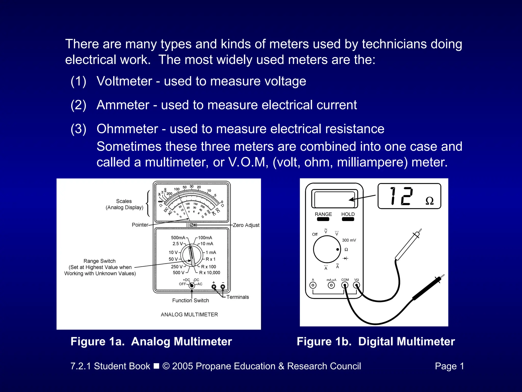
There are many types and kinds of meters used by technicians doing
electrical work. The most widely used meters are the:
(1) Voltmeter used to measure voltage
‑
(2) Ammeter used to measure electrical current
‑
(3) Ohmmeter used to measure electrical resistance
‑
Sometimes these three meters are combined into one case and
called a multimeter, or V.O.M, (volt, ohm, milliampere) meter.
Figure 1a. Analog Multimeter Figure 1b. Digital Multimeter
- 4.
7.2.1 Student Book © 2005 Propane Education & Research Council Page 2
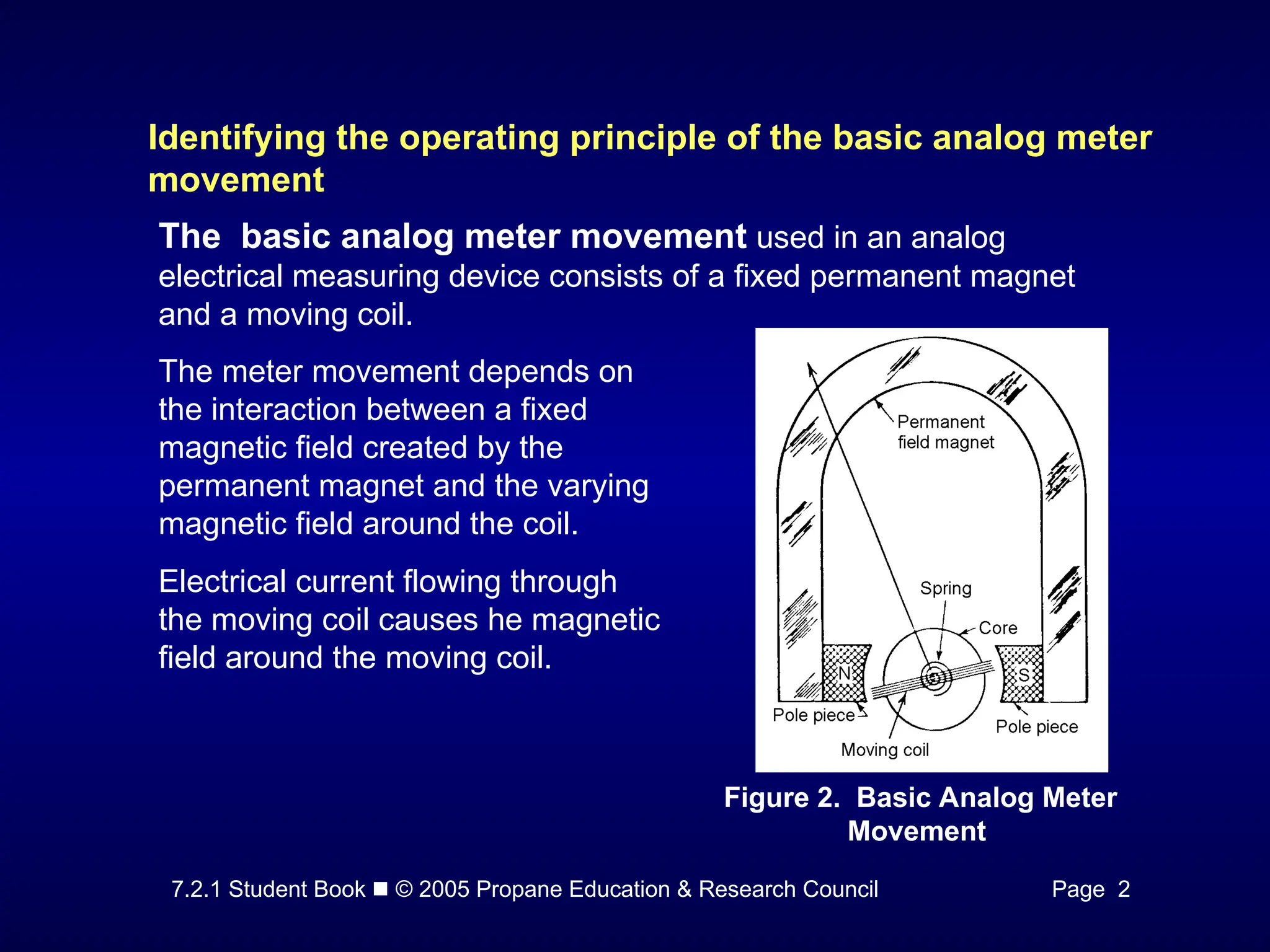
Identifying the operating principle of the basic analog meter
movement
The basic analog meter movement used in an analog
electrical measuring device consists of a fixed permanent magnet
and a moving coil.
The meter movement depends on
the interaction between a fixed
magnetic field created by the
permanent magnet and the varying
magnetic field around the coil.
Electrical current flowing through
the moving coil causes he magnetic
field around the moving coil.
Figure 2. Basic Analog Meter
Movement
- 5.
7.2.1 Student Book © 2005 Propane Education & Research Council Pages 2& 3
Identifying how to read a typical analog multimeter scale
Figure 3. Typical Analog Multimeter Face
- 6.
7.2.1 Student Book © 2005 Propane Education & Research Council Pages 2& 3
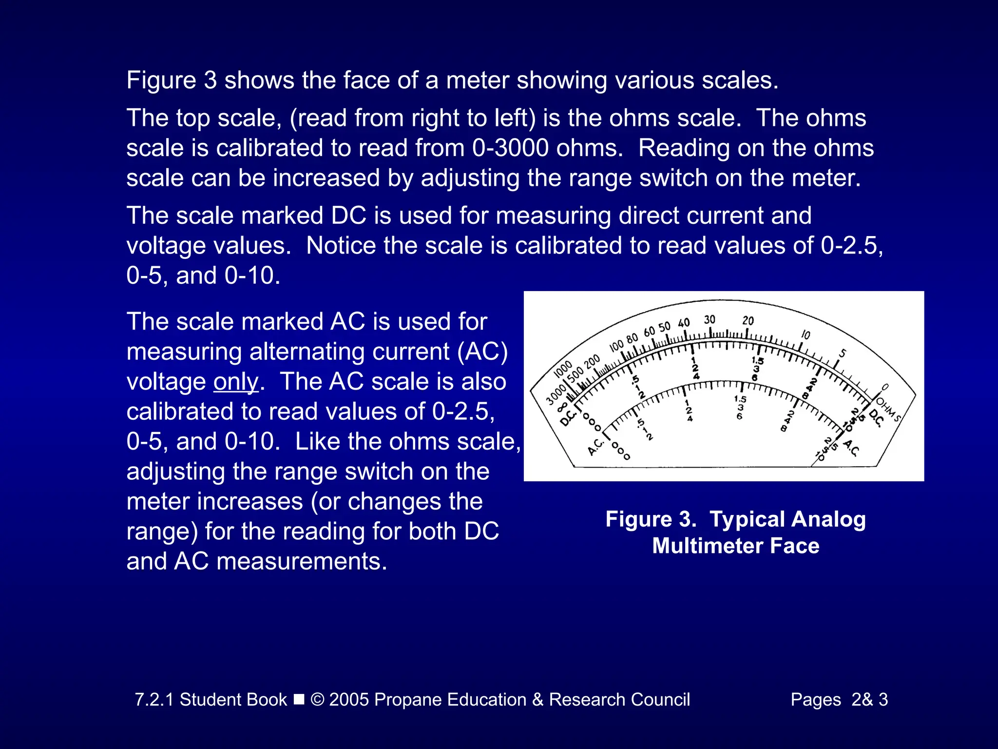
Figure 3 shows the face of a meter showing various scales.
The top scale, (read from right to left) is the ohms scale. The ohms
scale is calibrated to read from 0 3000 ohms. Reading on the ohms
‑
scale can be increased by adjusting the range switch on the meter.
The scale marked DC is used for measuring direct current and
voltage values. Notice the scale is calibrated to read values of 0 2.5,
‑
0 5, and 0 10.
‑ ‑
The scale marked AC is used for
measuring alternating current (AC)
voltage only. The AC scale is also
calibrated to read values of 0 2.5,
‑
0 5, and 0 10. Like the ohms scale,
‑ ‑
adjusting the range switch on the
meter increases (or changes the
range) for the reading for both DC
and AC measurements.
Figure 3. Typical Analog
Multimeter Face
- 7.
7.2.1 Student Book © 2005 Propane Education & Research Council Page 3
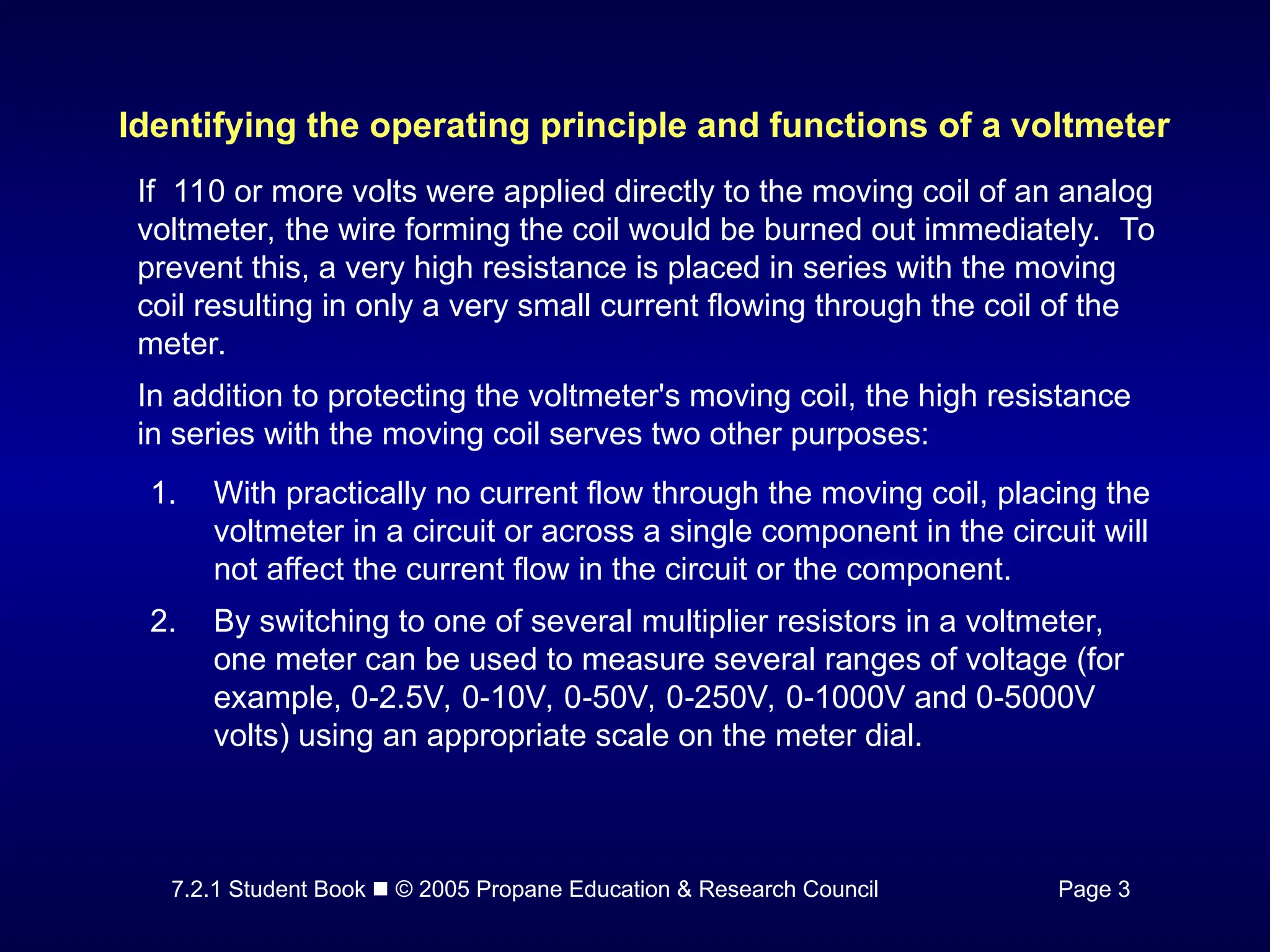
Identifying the operating principle and functions of a voltmeter
If 110 or more volts were applied directly to the moving coil of an analog
voltmeter, the wire forming the coil would be burned out immediately. To
prevent this, a very high resistance is placed in series with the moving
coil resulting in only a very small current flowing through the coil of the
meter.
In addition to protecting the voltmeter's moving coil, the high resistance
in series with the moving coil serves two other purposes:
1. With practically no current flow through the moving coil, placing the
voltmeter in a circuit or across a single component in the circuit will
not affect the current flow in the circuit or the component.
2. By switching to one of several multiplier resistors in a voltmeter,
one meter can be used to measure several ranges of voltage (for
example, 0 2.5V, 0 10V, 0 50V, 0 250V, 0 1000V and 0 5000V
‑ ‑ ‑ ‑ ‑ ‑
volts) using an appropriate scale on the meter dial.
- 8.
7.2.1 Student Book © 2005 Propane Education & Research Council Page 4
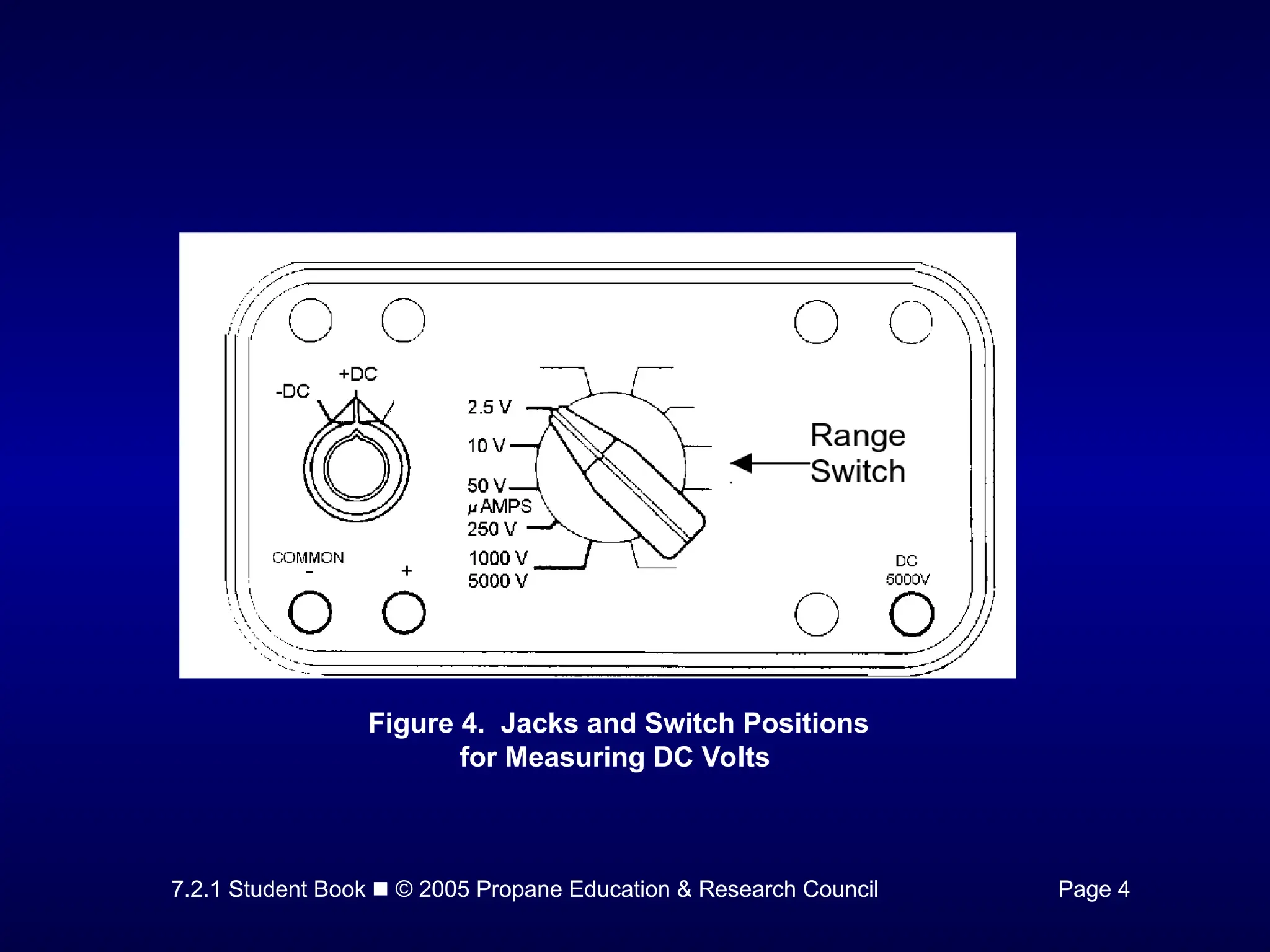
Figure 4. Jacks and Switch Positions
for Measuring DC Volts
- 9.
7.2.1 Student Book © 2005 Propane Education & Research Council Page 4
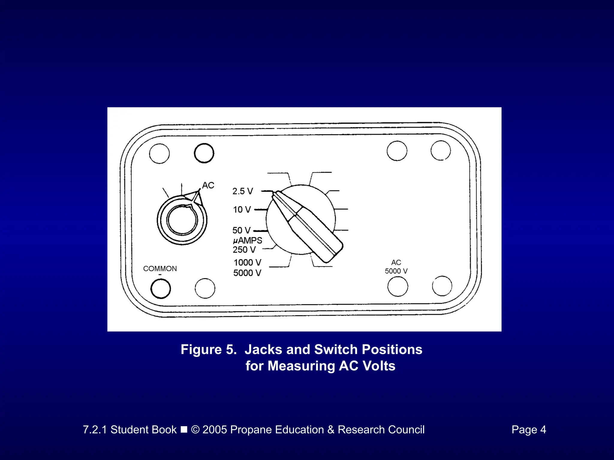
Figure 5. Jacks and Switch Positions
for Measuring AC Volts
- 10.
7.2.1 Student Book © 2005 Propane Education & Research Council Page 4
Figure 6 illustrates a scale calibrated to read the value of both DC and
AC volts. When DC voltage values are to be read, the selector switch
on the front of the meter is set on DC. If AC voltage values are to be
read, the selector switch is set on AC.
Figure 6. Meter Scale Calibrated to Measure AC or DC Volts
- 11.
7.2.1 Student Book © 2005 Propane Education & Research Council Page 5
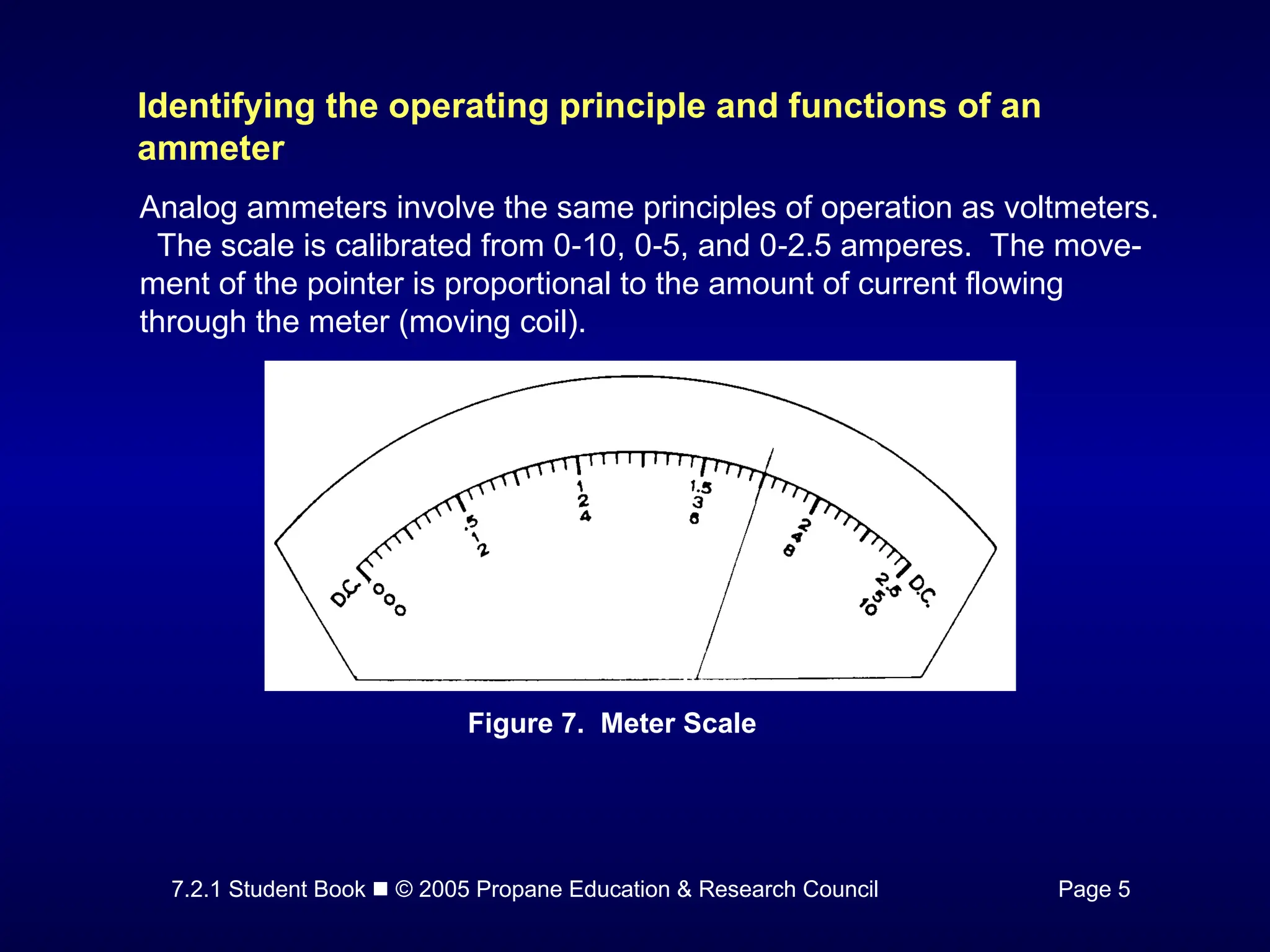
Identifying the operating principle and functions of an
ammeter
Analog ammeters involve the same principles of operation as voltmeters.
The scale is calibrated from 0 10, 0 5, and 0 2.5 amperes. The move-
‑ ‑ ‑
ment of the pointer is proportional to the amount of current flowing
through the meter (moving coil).
Figure 7. Meter Scale
- 12.
7.2.1 Student Book © 2005 Propane Education & Research Council Pages 5 & 6
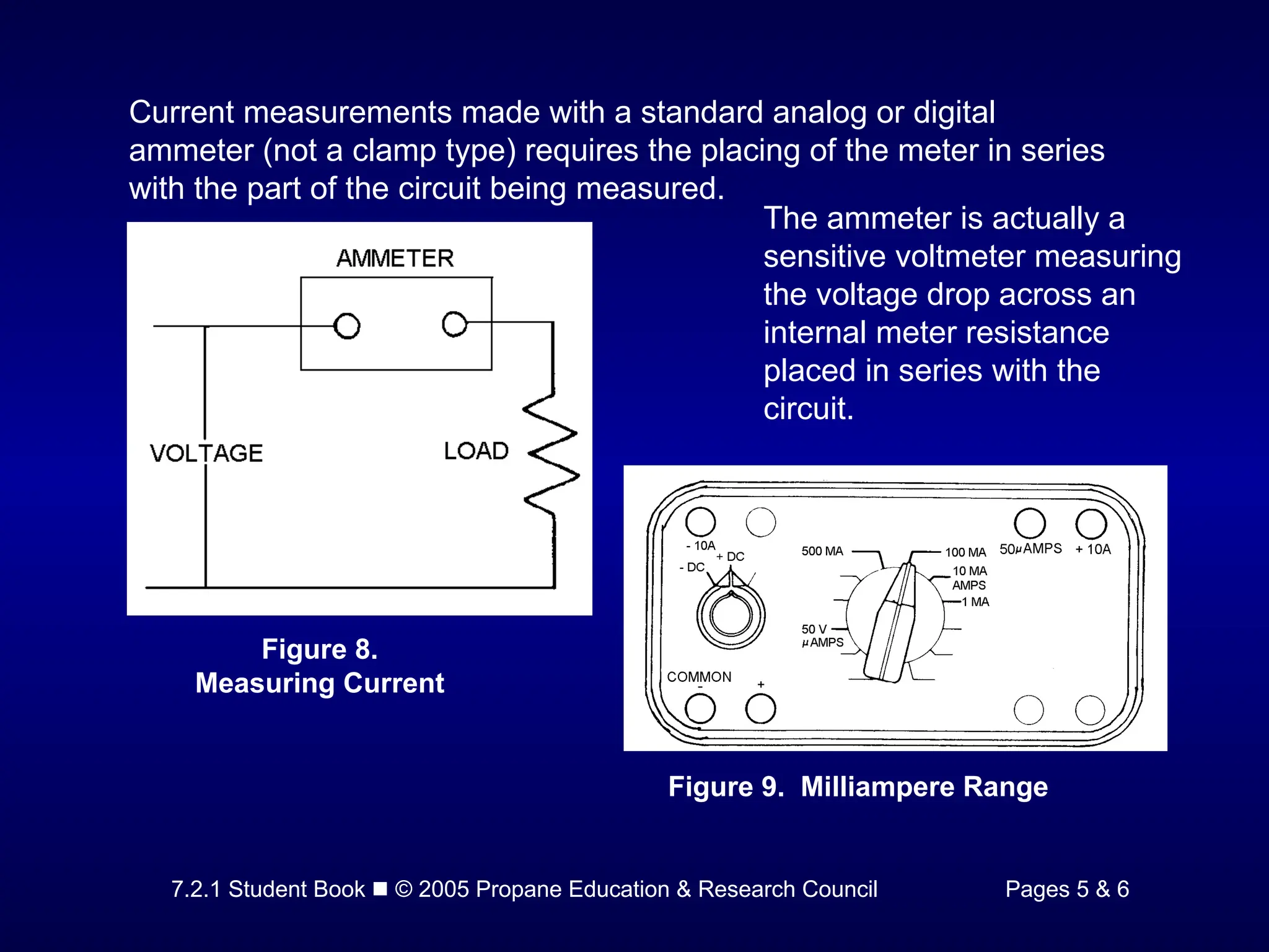
Current measurements made with a standard analog or digital
ammeter (not a clamp type) requires the placing of the meter in series
with the part of the circuit being measured.
The ammeter is actually a
sensitive voltmeter measuring
the voltage drop across an
internal meter resistance
placed in series with the
circuit.
Figure 8.
Measuring Current
Figure 9. Milliampere Range
- 13.
7.2.1 Student Book © 2005 Propane Education & Research Council Page 6
Identifying the operating principle and functions of an
ohmmeter
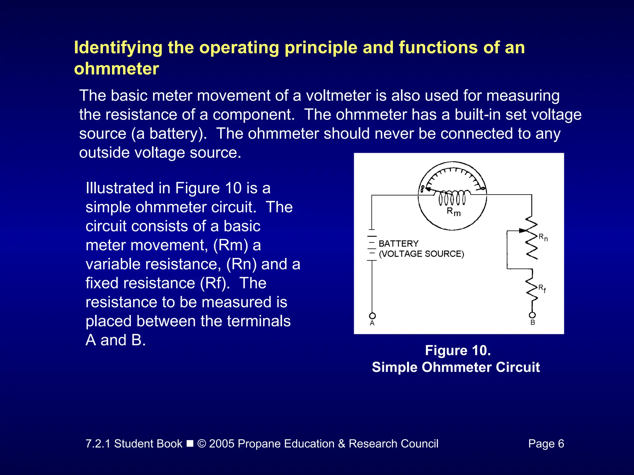
The basic meter movement of a voltmeter is also used for measuring
the resistance of a component. The ohmmeter has a built in set voltage
‑
source (a battery). The ohmmeter should never be connected to any
outside voltage source.
Illustrated in Figure 10 is a
simple ohmmeter circuit. The
circuit consists of a basic
meter movement, (Rm) a
variable resistance, (Rn) and a
fixed resistance (Rf). The
resistance to be measured is
placed between the terminals
A and B.
Figure 10.
Simple Ohmmeter Circuit
- 14.
7.2.1 Student Book © 2005 Propane Education & Research Council Page 6
Note the scale of an ohmmeter is the reverse of the voltmeter scale.
With the ohmmeter scale full deflection of the needle to the right end of
the scale is a reading of zero ohms, while the left end of the scale
indicates an infinite resistance, shown by the symbol:
- 15.
7.2.1 Student Book © 2005 Propane Education & Research Council Pages 6 & 7
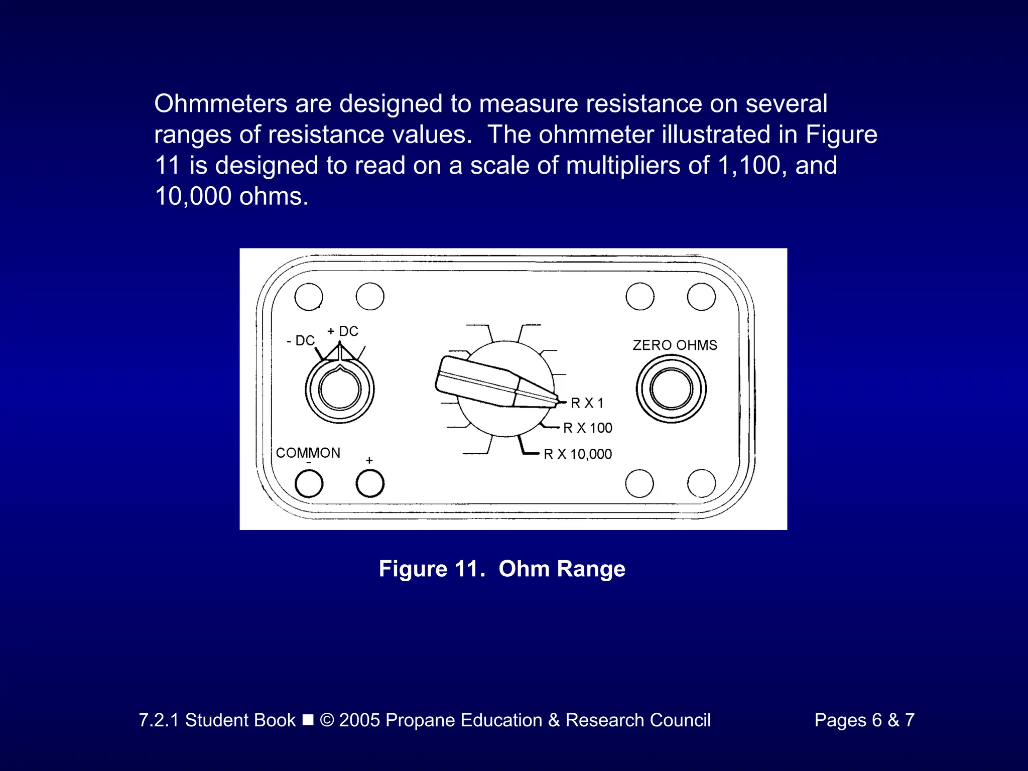
Ohmmeters are designed to measure resistance on several
ranges of resistance values. The ohmmeter illustrated in Figure
11 is designed to read on a scale of multipliers of 1,100, and
10,000 ohms.
Figure 11. Ohm Range
- 16.
7.2.1 Student Book © 2005 Propane Education & Research Council Page 7
Identifying the operating principle and functions of digital
multimeters (DMM)
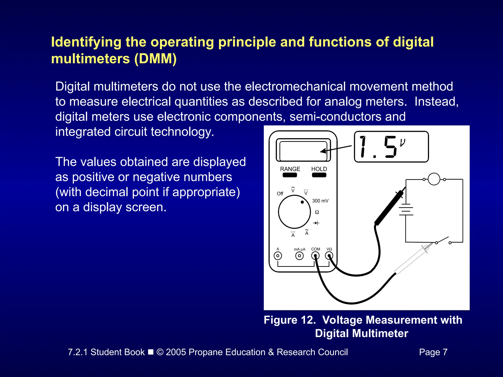
Digital multimeters do not use the electromechanical movement method
to measure electrical quantities as described for analog meters. Instead,
digital meters use electronic components, semi-conductors and
integrated circuit technology.
Figure 12. Voltage Measurement with
Digital Multimeter
The values obtained are displayed
as positive or negative numbers
(with decimal point if appropriate)
on a display screen.
- 17.
7.2.1 Student Book © 2005 Propane Education & Research Council Page 8
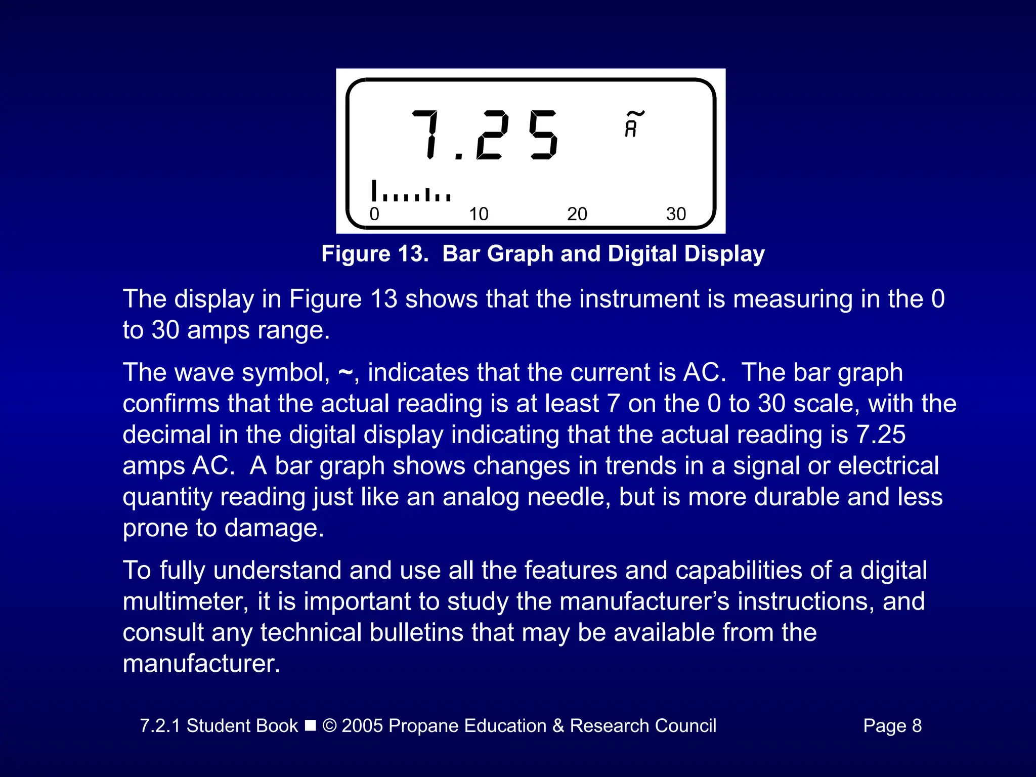
Figure 13. Bar Graph and Digital Display
The display in Figure 13 shows that the instrument is measuring in the 0
to 30 amps range.
The wave symbol, ~, indicates that the current is AC. The bar graph
confirms that the actual reading is at least 7 on the 0 to 30 scale, with the
decimal in the digital display indicating that the actual reading is 7.25
amps AC. A bar graph shows changes in trends in a signal or electrical
quantity reading just like an analog needle, but is more durable and less
prone to damage.
To fully understand and use all the features and capabilities of a digital
multimeter, it is important to study the manufacturer’s instructions, and
consult any technical bulletins that may be available from the
manufacturer.
- 18.
7.2.1 Student Book © 2005 Propane Education & Research Council Pages 8 & 9
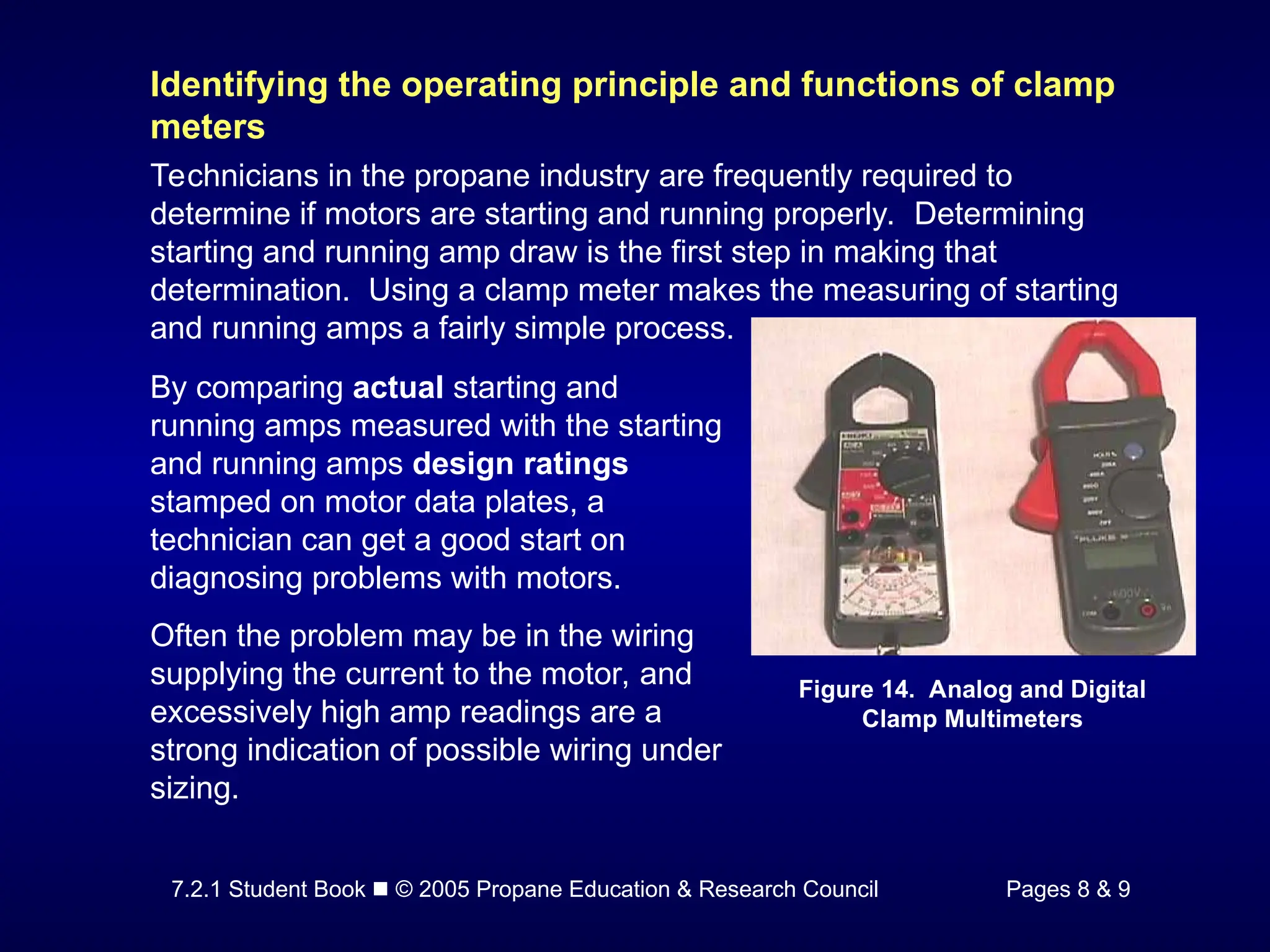
Identifying the operating principle and functions of clamp
meters
Technicians in the propane industry are frequently required to
determine if motors are starting and running properly. Determining
starting and running amp draw is the first step in making that
determination. Using a clamp meter makes the measuring of starting
and running amps a fairly simple process.
Figure 14. Analog and Digital
Clamp Multimeters
By comparing actual starting and
running amps measured with the starting
and running amps design ratings
stamped on motor data plates, a
technician can get a good start on
diagnosing problems with motors.
Often the problem may be in the wiring
supplying the current to the motor, and
excessively high amp readings are a
strong indication of possible wiring under
sizing.
- 19.
7.2.1 Student Book © 2005 Propane Education & Research Council Page 9
Identifying principles of meter safety and meter categories
Electric Shock
While most people are aware of the danger from electric shock, few
realize how little current and how low a voltage is required for a fatal
shock. Current flows as low as 30 mA can be fatal (1 mA = 1/1000A).
Let's look at the effects of current flow through a "typical" 150 pound
male:
• At about 10 mA, muscular paralysis of the arms occurs, so that he
cannot release his grip.
• At about 75-250 mA, for exposure exceeding 5 seconds,
ventricular fibrillation occurs, causing disruption of the coordination
of the heart muscles—the heart can no longer function. Higher
currents cause fibrillation at less than 5 seconds. The results are
often fatal.
Fluke Corporation, ABC's of Multimeter Safety
- 20.
7.2.1 Student Book © 2005 Propane Education & Research Council Page 9
Electric Shock
Now let's calculate the threshold for "hazardous" voltage. The
approximate body resistance under the skin from hand to hand across
the body is 1000, under dry conditions. A voltage of only 30V across
1000 will cause a current flow of 30 mA. Under wet conditions, or if
there is a cut in the skin, resistance drops radically. The threshold of
hazardous voltage is cut in half to 15V.
For multimeter manufacturers and users, the object is to prevent
accidental contact with live circuits at all costs. Look for:
• Meters and test leads with double insulation
• Meters with recessed input jacks and test leads with shrouded
input connectors
• Test leads with finger guards and a non-slip surface
• Meter and test leads made of high-quality, durable non-conductive
materials
Fluke Corporation, ABC's of Multimeter Safety
- 21.
7.2.1 Student Book © 2005 Propane Education & Research Council Page 10
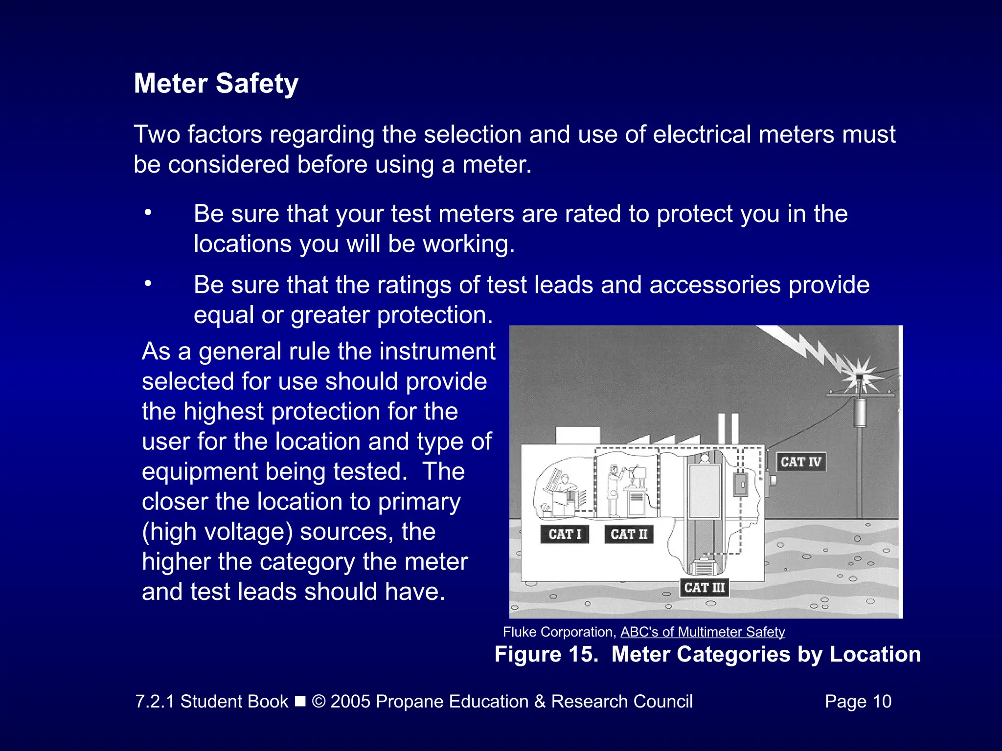
Meter Safety
Two factors regarding the selection and use of electrical meters must
be considered before using a meter.
• Be sure that your test meters are rated to protect you in the
locations you will be working.
• Be sure that the ratings of test leads and accessories provide
equal or greater protection.
Figure 15. Meter Categories by Location
Fluke Corporation, ABC's of Multimeter Safety
As a general rule the instrument
selected for use should provide
the highest protection for the
user for the location and type of
equipment being tested. The
closer the location to primary
(high voltage) sources, the
higher the category the meter
and test leads should have.
- 22.
7.2.1 Student Book © 2005 Propane Education & Research Council Page 11
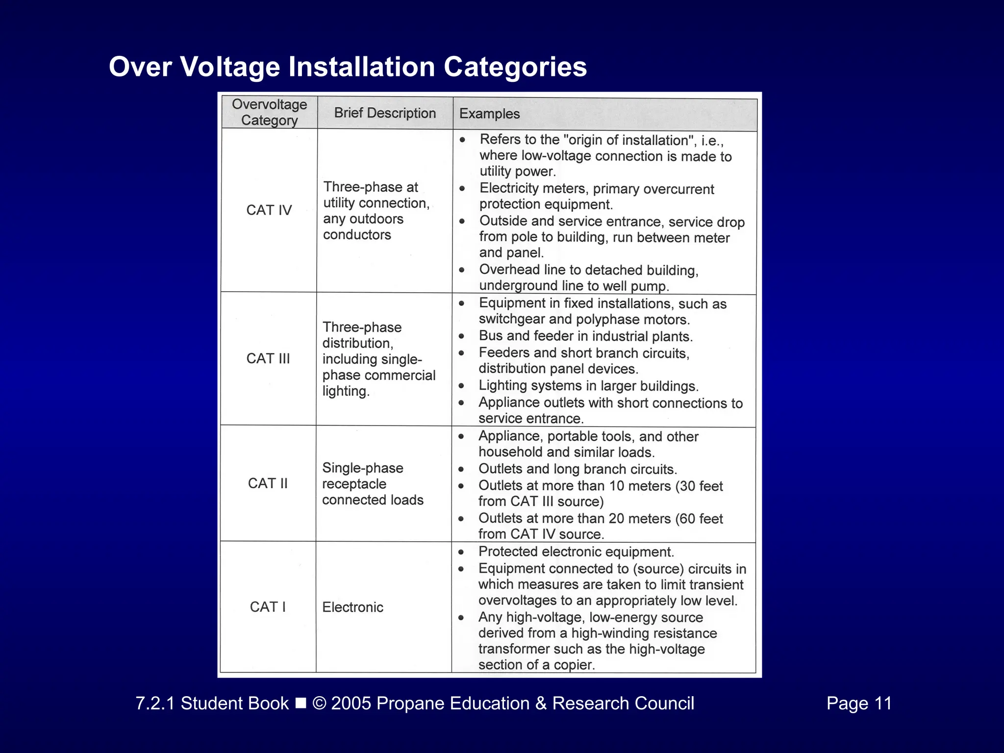
Over Voltage Installation Categories
- 23.
7.2.1 Student Book © 2005 Propane Education & Research Council Pages 11 & 12
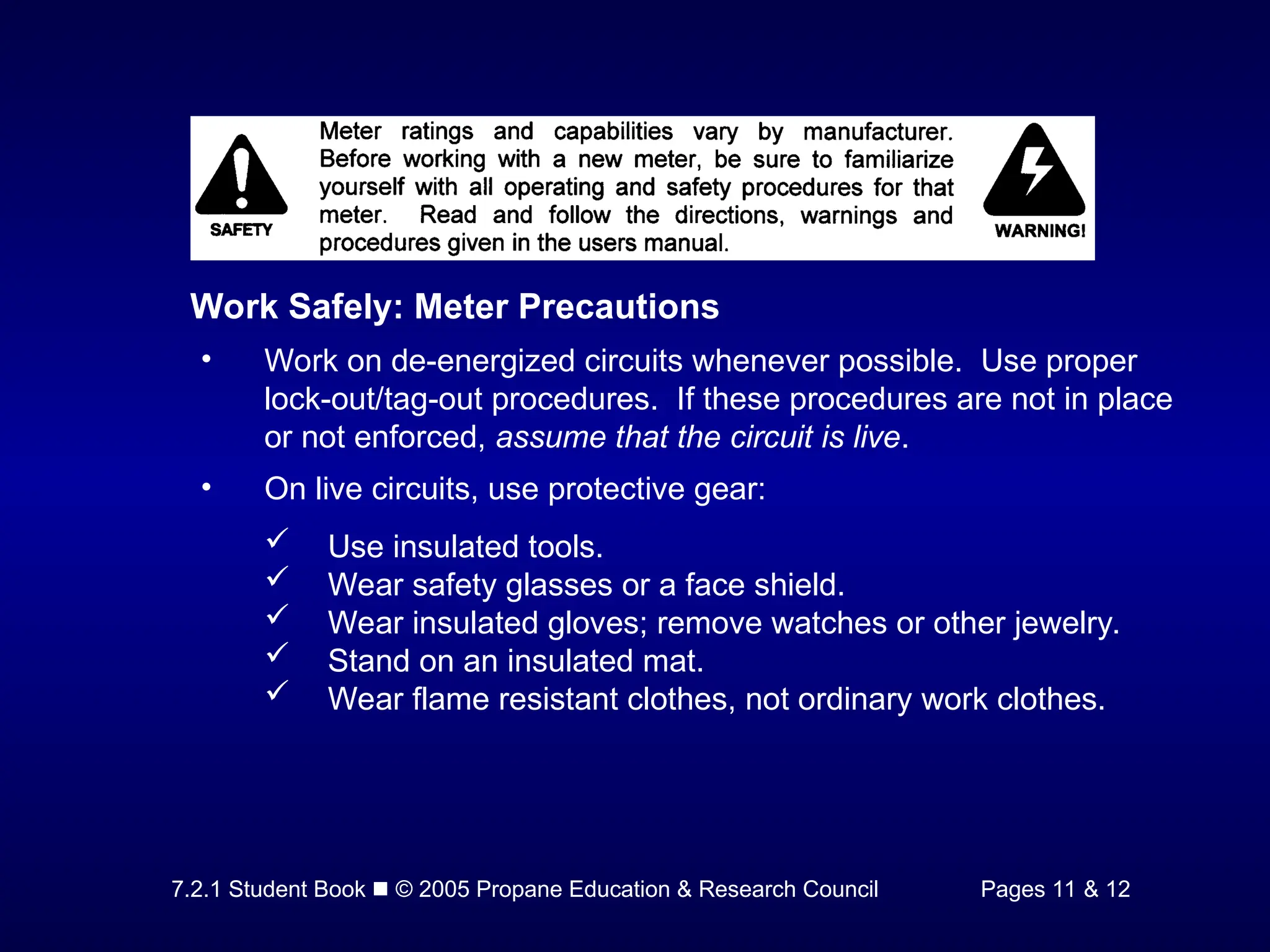
Work Safely: Meter Precautions
• Work on de-energized circuits whenever possible. Use proper
lock-out/tag-out procedures. If these procedures are not in place
or not enforced, assume that the circuit is live.
• On live circuits, use protective gear:
Use insulated tools.
Wear safety glasses or a face shield.
Wear insulated gloves; remove watches or other jewelry.
Stand on an insulated mat.
Wear flame resistant clothes, not ordinary work clothes.
- 24.
7.2.1 Student Book © 2005 Propane Education & Research Council Page 12
• When making measurements on live circuits:
Hook on the ground clip first then make contact with the hot
lead. Remove the hot lead first, the ground lead last.
Hang or rest the meter if possible. Try to avoid holding it in
your hands, to minimize personal exposure to the effects of
transients. (A transient is a momentary high voltage spike
which "rides" into circuits from an exterior source such as a
nearby lightning strike.)
Use the three-point test method, especially when checking to
see if a circuit is dead. First, test a known live circuit.
Second, test the target circuit. Third, test the live circuit
again. This verifies that your meter worked properly before
and after the measurement.
Use the old electricians' trick of keeping one hand in your
pocket. This lessens the chance of a closed circuit across
your chest and through your heart.
- 25.
7.2.1 Student Book © 2005 Propane Education & Research Council Pages 13 - 17
Time to See If You Got the Key Points of
This Module…
• Complete the Review on pages 13 -
16.
• See if you are ready for the
Certification Exam by checking off
the performance criteria on page 17.