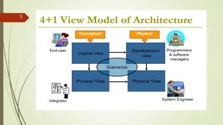
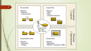
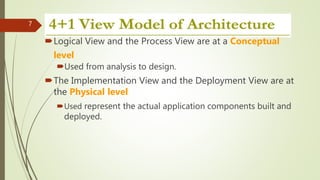
4+1 architectural view model
By Jainul Musani
1
4+1 Architectural view model
By Philippe Kruchten - Canadian software engineer,
Professor of Software Engineering at University of
British Columbia in Vancouver, Canada,
2
Introduction 4+1 architectural M. V.
4+1. describing the architecture of software-intensive
systems, based on the use of multiple, concurrent views.
The views are used to describe the system from the
viewpoint of different stakeholders,
such as
o End-users,
o Developers,
o project managers and
o System Engineers.
3
Introduction 4+1 architectural M. V.
The four views of the model are_
 Logical view,
 Development view,
 Process view and
 Physical view.
In addition selected use cases or scenarios
as the 'plus one' view.
4
5
Conceptual Physical
6
Logical View and the Process View are at a Conceptual
level
Used from analysis to design.
The Implementation View and the Deployment View are at
the Physical level
Used represent the actual application components built and
deployed.
7
Logical view
(Object-oriented Decomposition)
Logical Architects use this view for functional analysis
UML diagrams used to represent the logical view include,
class diagrams, and state diagrams.
Viewer:End-user
considers: Functional requirements-What the system
should provide in terms of services to its users.
8
Logical view
The system is decomposed into a set of key abstractions,
taken (mostly) from the problem domain, in the form of
objects or object classes.
 They exploit the principles of abstraction, encapsulation,
and inheritance.
9
Logical view
10
Sequence Diagram of ATM
11
Logical View – Sequence Diagram
12
13
List of online tools to create diagrams
 https://www.draw.io/
 https://www.gliffy.com/
 https://cacoo.com/
 https://www.processon.com/
 https://www.lucidchart.com/
 http://diagramo.com/
 https://creately.com/
14
Class Diagram15
Class Diagram16
Class Diagram17
Process View
 (The process decomposition)
 Viewer:Integrators
 Considers: Non -functional requirements
 This view considers non-functional aspects such as
 performance,
 Concurrency,
 scalability and
 throughput.
 To understand the organization processes, the process architectural view is used
in the Analysis and Design.
18
Process View
 The process view allows you to show
 what the system does at a high level, and
 how the smaller steps within the process fit together.
 It clears the processes steps, order and flow of information.
 the major flows of information through the system well understood and
documented.
19
Process view example
20
Process view example
21
Implementation View
 (Subsystem decomposition)
 Viewer: Programmers and Software Managers
 Considers: software module organization
(Hierarchy of layers, software management,
reuse, constraints of tools)
 Focuses on configuration management and actual software module organization.
 Component Diagrams are used to represent the Implementation View
 These diagrams show different components, the ports available and the
dependencies on the environment in terms of provided and required interfaces.
22
The implementation view is useful for:
assigning implementation work to individuals and
teams, or subcontractors
assessing the amount of code to be developed,
modified, or deleted
reasoning large-scale reuse
considering release strategies
23
Implementation View
24
Implementation View
Package Architecture
25
Physical View
 (Mapping the software to the Hardware)
 Viewer: System Engineers
 Considers: Non-functional req. regarding to underlying hardware
(Topology, Communication)
 Understanding the physical distribution of the system across a set of processing
nodes.
 The distribution of processing across a set of nodes in the system, including the
physical distribution of processes and threads.
26
Physical / Deployment View
27
Deployment of ATM / Physical
28
Scenario View
 (Putting it all together)
 Viewer: All users of other views and Evaluators.
 Considers: System consistency, validity
 Notation: almost similar to logical view
 The scenarios describe sequences of interactions between objects
and between processes.
 a use case is a list of actions or event steps typically defining the
interactions between a role (known in the UML as an actor) and a
system to achieve a goal.
 The actor can be a human or other external system.
 In systems engineering use cases are used at a higher level than
within software engineering often representing missions or
stakeholder goals.
29
Scenario View
30
Scenario Diagram – Usecase - ATM
31
32
USE CASE for Inventory
33
Bibliography
1) https://en.wikipedia.org/wiki/4%2B1_architectural_view_model
2) http://cic.javerianacali.edu.co/wiki/lib/exe/fetch.php?media=materias:mazeiar-
kruchten-4_1.pdf
3) http://www.ece.uvic.ca/~itraore/seng422-06/notes/arch06-3-2.pdf
4) http://sce.uhcl.edu/helm/rationalunifiedprocess/process/workflow/ana_desi/co_lview.
htm
5) https://technowiki.wordpress.com/2013/05/08/software-architecture-document-
guidelines/
6) https://www.sparxsystems.com.au/downloads/whitepapers/FCGSS_US_WP_Applying
_4+1_w_UML2.pdf
7) https://www.lucidchart.com/blog/uml-diagram-templates 
34
For Self Practice Examples use the
following site
 https://www.lucidchart.com/blog/uml-diagram-
templates#sequence
35

4+1archi

  • 1.
    4+1 architectural viewmodel By Jainul Musani 1
  • 2.
    4+1 Architectural viewmodel By Philippe Kruchten - Canadian software engineer, Professor of Software Engineering at University of British Columbia in Vancouver, Canada, 2
  • 3.
    Introduction 4+1 architecturalM. V. 4+1. describing the architecture of software-intensive systems, based on the use of multiple, concurrent views. The views are used to describe the system from the viewpoint of different stakeholders, such as o End-users, o Developers, o project managers and o System Engineers. 3
  • 4.
    Introduction 4+1 architecturalM. V. The four views of the model are_  Logical view,  Development view,  Process view and  Physical view. In addition selected use cases or scenarios as the 'plus one' view. 4
  • 5.
  • 6.
  • 7.
    Logical View andthe Process View are at a Conceptual level Used from analysis to design. The Implementation View and the Deployment View are at the Physical level Used represent the actual application components built and deployed. 7
  • 8.
    Logical view (Object-oriented Decomposition) LogicalArchitects use this view for functional analysis UML diagrams used to represent the logical view include, class diagrams, and state diagrams. Viewer:End-user considers: Functional requirements-What the system should provide in terms of services to its users. 8
  • 9.
    Logical view The systemis decomposed into a set of key abstractions, taken (mostly) from the problem domain, in the form of objects or object classes.  They exploit the principles of abstraction, encapsulation, and inheritance. 9
  • 10.
  • 11.
  • 12.
    Logical View –Sequence Diagram 12
  • 13.
  • 14.
    List of onlinetools to create diagrams  https://www.draw.io/  https://www.gliffy.com/  https://cacoo.com/  https://www.processon.com/  https://www.lucidchart.com/  http://diagramo.com/  https://creately.com/ 14
  • 15.
  • 16.
  • 17.
  • 18.
    Process View  (Theprocess decomposition)  Viewer:Integrators  Considers: Non -functional requirements  This view considers non-functional aspects such as  performance,  Concurrency,  scalability and  throughput.  To understand the organization processes, the process architectural view is used in the Analysis and Design. 18
  • 19.
    Process View  Theprocess view allows you to show  what the system does at a high level, and  how the smaller steps within the process fit together.  It clears the processes steps, order and flow of information.  the major flows of information through the system well understood and documented. 19
  • 20.
  • 21.
  • 22.
    Implementation View  (Subsystemdecomposition)  Viewer: Programmers and Software Managers  Considers: software module organization (Hierarchy of layers, software management, reuse, constraints of tools)  Focuses on configuration management and actual software module organization.  Component Diagrams are used to represent the Implementation View  These diagrams show different components, the ports available and the dependencies on the environment in terms of provided and required interfaces. 22
  • 23.
    The implementation viewis useful for: assigning implementation work to individuals and teams, or subcontractors assessing the amount of code to be developed, modified, or deleted reasoning large-scale reuse considering release strategies 23 Implementation View
  • 24.
  • 25.
  • 26.
    Physical View  (Mappingthe software to the Hardware)  Viewer: System Engineers  Considers: Non-functional req. regarding to underlying hardware (Topology, Communication)  Understanding the physical distribution of the system across a set of processing nodes.  The distribution of processing across a set of nodes in the system, including the physical distribution of processes and threads. 26
  • 27.
  • 28.
    Deployment of ATM/ Physical 28
  • 29.
    Scenario View  (Puttingit all together)  Viewer: All users of other views and Evaluators.  Considers: System consistency, validity  Notation: almost similar to logical view  The scenarios describe sequences of interactions between objects and between processes.  a use case is a list of actions or event steps typically defining the interactions between a role (known in the UML as an actor) and a system to achieve a goal.  The actor can be a human or other external system.  In systems engineering use cases are used at a higher level than within software engineering often representing missions or stakeholder goals. 29
  • 30.
  • 31.
    Scenario Diagram –Usecase - ATM 31
  • 32.
  • 33.
    USE CASE forInventory 33
  • 34.
    Bibliography 1) https://en.wikipedia.org/wiki/4%2B1_architectural_view_model 2) http://cic.javerianacali.edu.co/wiki/lib/exe/fetch.php?media=materias:mazeiar- kruchten-4_1.pdf 3)http://www.ece.uvic.ca/~itraore/seng422-06/notes/arch06-3-2.pdf 4) http://sce.uhcl.edu/helm/rationalunifiedprocess/process/workflow/ana_desi/co_lview. htm 5) https://technowiki.wordpress.com/2013/05/08/software-architecture-document- guidelines/ 6) https://www.sparxsystems.com.au/downloads/whitepapers/FCGSS_US_WP_Applying _4+1_w_UML2.pdf 7) https://www.lucidchart.com/blog/uml-diagram-templates  34
  • 35.
    For Self PracticeExamples use the following site  https://www.lucidchart.com/blog/uml-diagram- templates#sequence 35