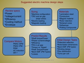
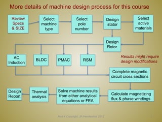
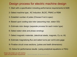
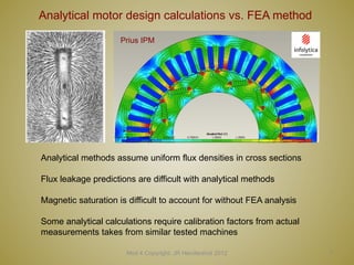
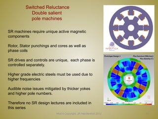
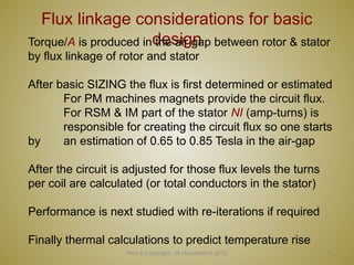
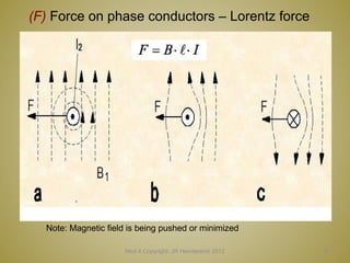
Mod 4 Copyright: JR Hendershot 2012 1
Electric Machine Design Course
Practical Design Process for Electrical Machines
Lecture # 4
2
Suggested electric machine design steps
Mod 4 Copyright: JR Hendershot 2012
Review specs
•Power
•Voltage/current
•Efficiency
•Cooling method
•Envelope
Sizing
•Machine configuration
•TRV and air gap
shear stress
•Electric loading
•Magnetic loading
Materials
•Lamination steel
•Conductors
•Magnet material
•Rotor retention
•Sintered cores
•Adhesives
•Potting Compounds
Initial Design Tasks
•Poles/slot selection
•Rotor/stator dimensions
•Back EMF (PM types)
•Winding design
•Flux distribution
•Turns per coil
Predict Results
•Shaft torque/Power
•Phase current/voltage
•Efficiency
•PSI in air gap
•Torque vs. Speed
•Peak Torque/Power
•Back EMF (PM Types)
•Losses
Compare Motors
PMAC SPM
PMAC IPM
RSM
AC Induction
SR ?
More details of machine design process for this course
Mod 4 Copyright: JR Hendershot 2012 3
Review
Specs
& SIZE
Select
machine
type
Select
pole
number
Design
stator
Select
active
materials
Design
Rotor
AC
Induction
BLDC PMAC RSM
Complete magnetic
circuit cross sections
Calculate magnetizing
flux & phase windings
Solve machine results
from either analytical
equations or FEA
Design
Report
Thermal
analysis
Results might require
design modifications
Mod 4 Copyright: JR Hendershot 2012 4
Design process for electric machine design
1- Start with a specification including performance requirements & SIZE
2- Select machine type, AC Induction, BLDC, PMAC or RSM
3- Establish number of poles (Choose if not in spec)
4- Based upon cooling size rotor (assuming max .stator OD)
5- Estimate rotor design (separate process for each motor type)
6- Select stator slots and phase windings
7- Select magnetic materials, (electrical steels, magnets, Cu vs. Al)
8- Estimate magnetizing flux and select turns per coil & wire gage
9- Finalize circuit cross sections, (yokes and teeth dimensions)
10- Solve for performance results (using analytical equations or FEA)
Design step details vary with machine
types and specification requirements
5
Most any electrical machine can be used
for motoring or generating or both
Mod 4 Copyright: JR Hendershot 2012
For motoring, the efficient production of shaft torque at
desired speeds is the most important parameter to
understand, design, predict & validate.
For generating, the efficient production of electrical power
at certain speeds and voltages is the most important
parameter to understand, design predict & validate.
Some IM & BLDC machines must be designed to be both
generators and motors such a starter/generator for a gas
turbines or IC engines.
(See four quadrant operation in Lecture # 2)
Mod 4 Copyright: JR Hendershot 2012 6
Classical design vs. practical design
Historical electric machine design courses and workshops
- Provide in depth analysis of classical concepts
Maxwell equations
Biot-Savart’s Law
Lorentz forces
Ampere’s Law
Faraday’s Law
- Frequently there is insufficient time for teaching actual
machine design steps that must be left up to
the students
to learn on the job depending upon their interest
The purpose of these lectures is too fill in that gap, to provide a
process for the design process along with practical guidelines
based upon a century of experience from the countless number
of electric machine designers and engineers around the world.
Mod 4 Copyright: JR Hendershot 2012 7
Analytical motor design calculations vs. FEA method
Analytical methods assume uniform flux densities in cross sections
Flux leakage predictions are difficult with analytical methods
Magnetic saturation is difficult to account for without FEA analysis
Some analytical calculations require calibration factors from actual
measurements takes from similar tested machines
Prius IPM
8
Important machine design considerations
Mod 4 Copyright: JR Hendershot 2012
Machines design for low cost mfg. to compete sometimes dictate designs
Existing infrastructure for manufacturing, winding & assembly tooling
Existing tooled components such as stator/rotor laminations
High volume potential in new market allows new tooling and infrastructure
Design can be optimized without manufacturing restraints
Allows “clean sheet of paper design”
Allows unusual configurations and magnetic material choices
(Such axial flux and transverse flux or hybrid PM/SR configurations)
Compact high torque/power density requirements (extreme cooling required)
Short end turn phase coils
High copper slot fill percentages
Hollow round or rectangular conductors (can be internally cooled)
Difficult operating environments, vacuum, hermetic, nuclear, cryogenic or hot.
Special materials and manufacturing processes
9
Comparison of machine types
Mod 4 Copyright: JR Hendershot 2012
A comparison study of IM and PM machine (M. J. Melfi, S. Evon and R.Mcelveen,
“Induction vs Permanent Magnet Motors”, IEEE Industry Applications Magnazine, pp. 28-35,
Nov-Dec 2009)
AC Induction, SPM-AC brushless & IPM-AC brushless
machine comparisons, 75 HP, 1800 rpm, voltage range
400 to 460, common stator core with different windings,
10
RSM machine comparison to IM
Mod 4 Copyright: JR Hendershot 2012
Data from ABB
Mod 4 Copyright: JR Hendershot 2012 11
Machines with non-salient pole rotors
AC Induction (IM) PM Synchronous, Wound Field Synchronous & RSM
Phase most common for all non-salient pole machines: (3, 6, or 9)
Same stator punching can be used for all
New rotor design for each one
Lamination materials are the same
Phase windings can be the same
PM synchronous need not have same pole number if both rotor & stator
Begin with scaled motor cross section to use working the final design
12
Design of common components
Mod 4 Copyright: JR Hendershot 2012
Initial SIZING based upon cooling, duty cycle and specifications
Selection of slots, poles and phases (rotor bars for AC induction)
Certain SPM machines might use single tooth windings
Stator lamination design, electrical steel choices
Iron loss considerations
Select necessary insulation class to meet specification
Stator phase windings and coil placements (turns/coil later)
Plan for potential cooling using air or liquid
13
Switched Reluctance
Double salient
pole machines
Mod 4 Copyright: JR Hendershot 2012
SR machines require unique active magnetic
components
Rotor, Stator punchings and cores as well as
phase coils
SR drives and controls are unique, each phase is
controlled separately.
Higher grade electric steels must be used due to
higher frequencies
Audible noise issues mitigated by thicker yokes
and higher pole numbers.
Therefore no SR design lectures are included in
this series
Mod 4 Copyright: JR Hendershot 2012 14
Principles of electric machine design
Focus on designing electrical machines to produce torque efficiently rather
than focusing on producing power.
Torque is produced within air-gap between rotor & stator two different ways
Non-salient pole machines, Lorentz forces (F =B l I ) times
radius
Salient pole machines, reluctance force time radius
Both cases magnetic forces
are used to produce torque
because the minimization of
magnetic field energy as the
air gap is reduced between
the rotor poles and the stator.
15
Flux linkage considerations for basic
design
Mod 4 Copyright: JR Hendershot 2012
Torque/A is produced in the air gap between rotor & stator
by flux linkage of rotor and stator
After basic SIZING the flux is first determined or estimated
For PM machines magnets provide the circuit flux.
For RSM & IM part of the stator NI (amp-turns) is
responsible for creating the circuit flux so one starts
by an estimation of 0.65 to 0.85 Tesla in the air-gap
After the circuit is adjusted for those flux levels the turns
per coil are calculated (or total conductors in the stator)
Performance is next studied with re-iterations if required
Finally thermal calculations to predict temperature rise
16
Mod 4 Copyright: JR Hendershot 2012
(F) Force on phase conductors – Lorentz force
Note: Magnetic field is being pushed or minimized
17
Title
Mod 4 Copyright: JR Hendershot 2012

4 Practica design process for elect. machines.pptx

  • 1.
    Mod 4 Copyright:JR Hendershot 2012 1 Electric Machine Design Course Practical Design Process for Electrical Machines Lecture # 4
  • 2.
    2 Suggested electric machinedesign steps Mod 4 Copyright: JR Hendershot 2012 Review specs •Power •Voltage/current •Efficiency •Cooling method •Envelope Sizing •Machine configuration •TRV and air gap shear stress •Electric loading •Magnetic loading Materials •Lamination steel •Conductors •Magnet material •Rotor retention •Sintered cores •Adhesives •Potting Compounds Initial Design Tasks •Poles/slot selection •Rotor/stator dimensions •Back EMF (PM types) •Winding design •Flux distribution •Turns per coil Predict Results •Shaft torque/Power •Phase current/voltage •Efficiency •PSI in air gap •Torque vs. Speed •Peak Torque/Power •Back EMF (PM Types) •Losses Compare Motors PMAC SPM PMAC IPM RSM AC Induction SR ?
  • 3.
    More details ofmachine design process for this course Mod 4 Copyright: JR Hendershot 2012 3 Review Specs & SIZE Select machine type Select pole number Design stator Select active materials Design Rotor AC Induction BLDC PMAC RSM Complete magnetic circuit cross sections Calculate magnetizing flux & phase windings Solve machine results from either analytical equations or FEA Design Report Thermal analysis Results might require design modifications
  • 4.
    Mod 4 Copyright:JR Hendershot 2012 4 Design process for electric machine design 1- Start with a specification including performance requirements & SIZE 2- Select machine type, AC Induction, BLDC, PMAC or RSM 3- Establish number of poles (Choose if not in spec) 4- Based upon cooling size rotor (assuming max .stator OD) 5- Estimate rotor design (separate process for each motor type) 6- Select stator slots and phase windings 7- Select magnetic materials, (electrical steels, magnets, Cu vs. Al) 8- Estimate magnetizing flux and select turns per coil & wire gage 9- Finalize circuit cross sections, (yokes and teeth dimensions) 10- Solve for performance results (using analytical equations or FEA) Design step details vary with machine types and specification requirements
  • 5.
    5 Most any electricalmachine can be used for motoring or generating or both Mod 4 Copyright: JR Hendershot 2012 For motoring, the efficient production of shaft torque at desired speeds is the most important parameter to understand, design, predict & validate. For generating, the efficient production of electrical power at certain speeds and voltages is the most important parameter to understand, design predict & validate. Some IM & BLDC machines must be designed to be both generators and motors such a starter/generator for a gas turbines or IC engines. (See four quadrant operation in Lecture # 2)
  • 6.
    Mod 4 Copyright:JR Hendershot 2012 6 Classical design vs. practical design Historical electric machine design courses and workshops - Provide in depth analysis of classical concepts Maxwell equations Biot-Savart’s Law Lorentz forces Ampere’s Law Faraday’s Law - Frequently there is insufficient time for teaching actual machine design steps that must be left up to the students to learn on the job depending upon their interest The purpose of these lectures is too fill in that gap, to provide a process for the design process along with practical guidelines based upon a century of experience from the countless number of electric machine designers and engineers around the world.
  • 7.
    Mod 4 Copyright:JR Hendershot 2012 7 Analytical motor design calculations vs. FEA method Analytical methods assume uniform flux densities in cross sections Flux leakage predictions are difficult with analytical methods Magnetic saturation is difficult to account for without FEA analysis Some analytical calculations require calibration factors from actual measurements takes from similar tested machines Prius IPM
  • 8.
    8 Important machine designconsiderations Mod 4 Copyright: JR Hendershot 2012 Machines design for low cost mfg. to compete sometimes dictate designs Existing infrastructure for manufacturing, winding & assembly tooling Existing tooled components such as stator/rotor laminations High volume potential in new market allows new tooling and infrastructure Design can be optimized without manufacturing restraints Allows “clean sheet of paper design” Allows unusual configurations and magnetic material choices (Such axial flux and transverse flux or hybrid PM/SR configurations) Compact high torque/power density requirements (extreme cooling required) Short end turn phase coils High copper slot fill percentages Hollow round or rectangular conductors (can be internally cooled) Difficult operating environments, vacuum, hermetic, nuclear, cryogenic or hot. Special materials and manufacturing processes
  • 9.
    9 Comparison of machinetypes Mod 4 Copyright: JR Hendershot 2012 A comparison study of IM and PM machine (M. J. Melfi, S. Evon and R.Mcelveen, “Induction vs Permanent Magnet Motors”, IEEE Industry Applications Magnazine, pp. 28-35, Nov-Dec 2009) AC Induction, SPM-AC brushless & IPM-AC brushless machine comparisons, 75 HP, 1800 rpm, voltage range 400 to 460, common stator core with different windings,
  • 10.
    10 RSM machine comparisonto IM Mod 4 Copyright: JR Hendershot 2012 Data from ABB
  • 11.
    Mod 4 Copyright:JR Hendershot 2012 11 Machines with non-salient pole rotors AC Induction (IM) PM Synchronous, Wound Field Synchronous & RSM Phase most common for all non-salient pole machines: (3, 6, or 9) Same stator punching can be used for all New rotor design for each one Lamination materials are the same Phase windings can be the same PM synchronous need not have same pole number if both rotor & stator Begin with scaled motor cross section to use working the final design
  • 12.
    12 Design of commoncomponents Mod 4 Copyright: JR Hendershot 2012 Initial SIZING based upon cooling, duty cycle and specifications Selection of slots, poles and phases (rotor bars for AC induction) Certain SPM machines might use single tooth windings Stator lamination design, electrical steel choices Iron loss considerations Select necessary insulation class to meet specification Stator phase windings and coil placements (turns/coil later) Plan for potential cooling using air or liquid
  • 13.
    13 Switched Reluctance Double salient polemachines Mod 4 Copyright: JR Hendershot 2012 SR machines require unique active magnetic components Rotor, Stator punchings and cores as well as phase coils SR drives and controls are unique, each phase is controlled separately. Higher grade electric steels must be used due to higher frequencies Audible noise issues mitigated by thicker yokes and higher pole numbers. Therefore no SR design lectures are included in this series
  • 14.
    Mod 4 Copyright:JR Hendershot 2012 14 Principles of electric machine design Focus on designing electrical machines to produce torque efficiently rather than focusing on producing power. Torque is produced within air-gap between rotor & stator two different ways Non-salient pole machines, Lorentz forces (F =B l I ) times radius Salient pole machines, reluctance force time radius Both cases magnetic forces are used to produce torque because the minimization of magnetic field energy as the air gap is reduced between the rotor poles and the stator.
  • 15.
    15 Flux linkage considerationsfor basic design Mod 4 Copyright: JR Hendershot 2012 Torque/A is produced in the air gap between rotor & stator by flux linkage of rotor and stator After basic SIZING the flux is first determined or estimated For PM machines magnets provide the circuit flux. For RSM & IM part of the stator NI (amp-turns) is responsible for creating the circuit flux so one starts by an estimation of 0.65 to 0.85 Tesla in the air-gap After the circuit is adjusted for those flux levels the turns per coil are calculated (or total conductors in the stator) Performance is next studied with re-iterations if required Finally thermal calculations to predict temperature rise
  • 16.
    16 Mod 4 Copyright:JR Hendershot 2012 (F) Force on phase conductors – Lorentz force Note: Magnetic field is being pushed or minimized
  • 17.
    17 Title Mod 4 Copyright:JR Hendershot 2012