Download to read offline

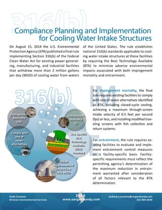
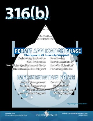
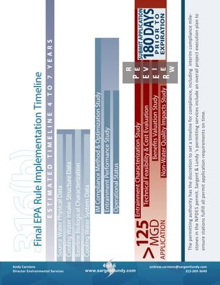
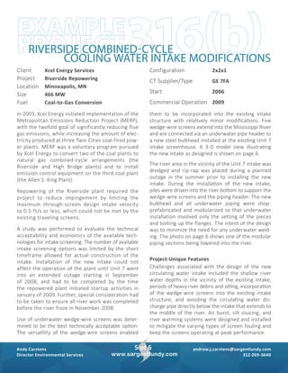
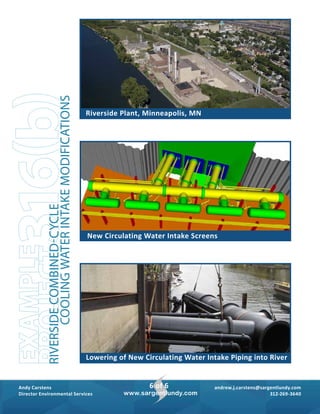

The document discusses the EPA's final rule under Section 316(b) of the Clean Water Act, which mandates existing facilities withdrawing more than 2 million gallons per day of cooling water to implement best technology available to minimize environmental impacts. It outlines compliance options for both impingement mortality and entrainment and provides details on project support services offered by Sargent & Lundy for permit applications and implementation phases. A specific project example is given for Xcel Energy's Riverside repowering initiative, detailing the design and installation of new cooling water intake technologies to meet the regulatory requirements.


![Wp special master-plan[071113]](https://cdn.slidesharecdn.com/ss_thumbnails/wpspecial-masterplan071113-130712181949-phpapp02-thumbnail.jpg?width=640&height=640&fit=bounds)


