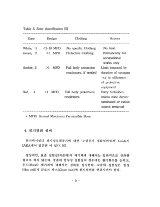
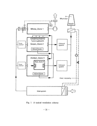
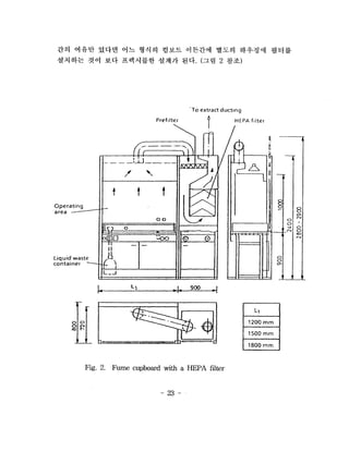
Design of the Ventilation System
    of the Nuclear Facility(l)
    - General Requirements -
Abstract

   Depending on the characteristics of processes, the quantity and
kinds of radioactive materials handled in the processes, nuclear
facilities produce the airborne radioactive nuclides and fission
products such as noble gas fission products and activation gases,
fission product idodine and aerosols.
   The primary purpose of the nuclear ventilation system is to
remove and/or reduce the release of radioactivity to the
environment, and to keep the facility atmosphere clear and safe. In
case of accidents, containment sprays and recirculation system in
reactor building remove heat from the containment atmosphere as
well as scrubbing airborne radioactivity.

   To assure that the operation of the nuclear ventilation system is
effective and economic, the resonable design of the system is
essential. As the nuclear ventilation system has to meet the
particular conditions; to keep the rooms at an below atmospheric
pressure at all times and, furthermore, to maintain frequent air
circulation in the rooms,      the system needs the big rotating
machinery. Consequently, the construction cost and the operational
cost of the ventilation system is very high.
    For maximum function with the minimum cost, areas are to be
divided into several zones depending on the level of radioactivity
and the once-through air flow in the shortest route should be
adopted. The pressure differences between the zones and the
number of air circulations in the rooms per unit time must be
reasonable, thus, the venting air volume should be of minimum.


                               -   11 -
Large venting air volume means large costs.
   Another way to minimize the venting air volume which needs
cleaning or filtration is to utilize the open boxes, glove boxes and
cells depending on the contamination risk of the work in the box.
It is a simple idea but a very effective method to reduce the
contaminated air, as a result, most of the exhausted air may be
released to the environment without treatment.


                               - HI -
3.


Table 1. Guidelines for effulent releases and dose limits for NPPs    3
Table 2. Risk analysis criteria for NPPs                              4
Table 3. Zone classification                                          9
Table 4. Annual limits of exposure                                   11
Table 5. Air cleaning requirements                                   13
Table 6. Relationships between US licencing guidelines
         and Engineering safety features (ESFs)                      37
Table 7. Emergency ventilation systems in other countries            39


                                 - vu -
Fig. 1. A typical ventilation scheme                                21
Fig. 2. Fume cupboard with a HEPA filter                            23
Fig. 3. Vortex amplifier (Normal position)                          26
Fig. 4. Vortex amplifier (Switch position)                          28
Fig. 5. Push-through filter system                                  31
Fig. 6. Containment purge system                                    33
Fig. 7. Block diagram of simplified PWR gaseous effulent
        treatment for normal and accident conditions                35
Fig. 8. Air cleaning system in reactor containment                  38
Fig. 9. Filter system at Barseback                                  40
Fig. 10. Multi-venturi water scrubber system for Swedish reactors   41
Fig. 11. Sand bed filter                                            42
Fig. 12. Stainless steel fiber filter                               43
Fig. 13. Venting system                                             44
Fig. 14. Functional diagram of the CANDU containment system         46
Fig. 15. Venting system concept                                     47
Fig. 16. Parallel battery of canister housings                      50
Fig. 17. Plug-in Circular insert filter housing                     52
Fig. 18. Shelf type housing systems                                 54
Fig. 19. Ladder type housing systems (Rectangular)                  55
Fig. 20. Ladder type housing systems (Circular)                     56
Fig. 21. Push-through filter change system                          57


                                        -   viii -
BIBLIOGRAPHIC INFORMATION SHEET
     Performing Qrg.         Sponsoring Qrg. Standard Report No.    IMS Subject Code
       Report No.              Report No.
  KAERI / TR-983 /98
      Title/Subtitle

                          Design of the ventilation systemd)
  Project Manager/Dept.
                                K M. Lee /Radioactive Waste Treatment Facility
    (or Main Author)
     Researcher/Dept

               I.S. Kang, S.M Bae, T.K Kim, KJ. Kim / RWTF
Pub. Place     Taejon         Pub. Org.            KAERI           Pub. Date 1998. 3
  Page            63 P.      Fig. &Tab. Yes ( v ), No (        )     Size       26 cm
  Note
                                                                            Technical
Classified Open ( v ), Outside (          ), Class (   ) Report Type
                                                                             Report
Sponsoring Org.                                          Contract No.
             Abstract

   To assure that the operation of the the nuclear ventilation system is
effective and economic, the resonable design of system is essential. As
the nuclear ventilation system has to meet the particular conditions; to
keep the rooms at an below atmospheric pressure at all times and,
furthermore, to maintain frequent air circulation in the rooms, the
system needs the big rotating machinery. Consequently, the
construction cost and the operational cost of the ventilation system is
very high.
    For maximum function with the minimum cost, areas are to be
divided into several zones depending on the level of radioactivity and
the once-through air flow in the shortest route should be adopted. The
pressure difference between the zones and the number of air
circulations per unit time in the rooms must be reasonable, thus, the
venting air volume should be of minimum.

         Subject Keywords


  ventilation system, zone, pressure difference, air circulation, once-through flow,

30045504

  • 1.
    Design of theVentilation System of the Nuclear Facility(l) - General Requirements -
  • 4.
    Abstract Depending on the characteristics of processes, the quantity and kinds of radioactive materials handled in the processes, nuclear facilities produce the airborne radioactive nuclides and fission products such as noble gas fission products and activation gases, fission product idodine and aerosols. The primary purpose of the nuclear ventilation system is to remove and/or reduce the release of radioactivity to the environment, and to keep the facility atmosphere clear and safe. In case of accidents, containment sprays and recirculation system in reactor building remove heat from the containment atmosphere as well as scrubbing airborne radioactivity. To assure that the operation of the nuclear ventilation system is effective and economic, the resonable design of the system is essential. As the nuclear ventilation system has to meet the particular conditions; to keep the rooms at an below atmospheric pressure at all times and, furthermore, to maintain frequent air circulation in the rooms, the system needs the big rotating machinery. Consequently, the construction cost and the operational cost of the ventilation system is very high. For maximum function with the minimum cost, areas are to be divided into several zones depending on the level of radioactivity and the once-through air flow in the shortest route should be adopted. The pressure differences between the zones and the number of air circulations in the rooms per unit time must be reasonable, thus, the venting air volume should be of minimum. - 11 -
  • 5.
    Large venting airvolume means large costs. Another way to minimize the venting air volume which needs cleaning or filtration is to utilize the open boxes, glove boxes and cells depending on the contamination risk of the work in the box. It is a simple idea but a very effective method to reduce the contaminated air, as a result, most of the exhausted air may be released to the environment without treatment. - HI -
  • 9.
    3. Table 1. Guidelinesfor effulent releases and dose limits for NPPs 3 Table 2. Risk analysis criteria for NPPs 4 Table 3. Zone classification 9 Table 4. Annual limits of exposure 11 Table 5. Air cleaning requirements 13 Table 6. Relationships between US licencing guidelines and Engineering safety features (ESFs) 37 Table 7. Emergency ventilation systems in other countries 39 - vu -
  • 10.
    Fig. 1. Atypical ventilation scheme 21 Fig. 2. Fume cupboard with a HEPA filter 23 Fig. 3. Vortex amplifier (Normal position) 26 Fig. 4. Vortex amplifier (Switch position) 28 Fig. 5. Push-through filter system 31 Fig. 6. Containment purge system 33 Fig. 7. Block diagram of simplified PWR gaseous effulent treatment for normal and accident conditions 35 Fig. 8. Air cleaning system in reactor containment 38 Fig. 9. Filter system at Barseback 40 Fig. 10. Multi-venturi water scrubber system for Swedish reactors 41 Fig. 11. Sand bed filter 42 Fig. 12. Stainless steel fiber filter 43 Fig. 13. Venting system 44 Fig. 14. Functional diagram of the CANDU containment system 46 Fig. 15. Venting system concept 47 Fig. 16. Parallel battery of canister housings 50 Fig. 17. Plug-in Circular insert filter housing 52 Fig. 18. Shelf type housing systems 54 Fig. 19. Ladder type housing systems (Rectangular) 55 Fig. 20. Ladder type housing systems (Circular) 56 Fig. 21. Push-through filter change system 57 - viii -
  • 75.
    BIBLIOGRAPHIC INFORMATION SHEET Performing Qrg. Sponsoring Qrg. Standard Report No. IMS Subject Code Report No. Report No. KAERI / TR-983 /98 Title/Subtitle Design of the ventilation systemd) Project Manager/Dept. K M. Lee /Radioactive Waste Treatment Facility (or Main Author) Researcher/Dept I.S. Kang, S.M Bae, T.K Kim, KJ. Kim / RWTF Pub. Place Taejon Pub. Org. KAERI Pub. Date 1998. 3 Page 63 P. Fig. &Tab. Yes ( v ), No ( ) Size 26 cm Note Technical Classified Open ( v ), Outside ( ), Class ( ) Report Type Report Sponsoring Org. Contract No. Abstract To assure that the operation of the the nuclear ventilation system is effective and economic, the resonable design of system is essential. As the nuclear ventilation system has to meet the particular conditions; to keep the rooms at an below atmospheric pressure at all times and, furthermore, to maintain frequent air circulation in the rooms, the system needs the big rotating machinery. Consequently, the construction cost and the operational cost of the ventilation system is very high. For maximum function with the minimum cost, areas are to be divided into several zones depending on the level of radioactivity and the once-through air flow in the shortest route should be adopted. The pressure difference between the zones and the number of air circulations per unit time in the rooms must be reasonable, thus, the venting air volume should be of minimum. Subject Keywords ventilation system, zone, pressure difference, air circulation, once-through flow,