RULES & REGULATIONS
•Shipbuilding vs. Offshore Standards
– piping
– selection of materials
– accommodations
– control & safety systems
• Safety
– IMO MODU as a reference
– SOLAS limited to specific items not covered by
MODU
– MARPOL with unified interpretation forFPSO’s
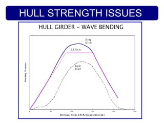
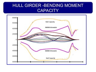
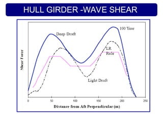
GLOBAL HULL DESIGN–WAVE BM & SF
• Still water loading conditions often more severe for FPSO
• Wave loading depends upon site environmental criteria:
– harsh environment wave BM and SF are close to and may exceed Ship
Rule requirements
– benign environment wave BM and SF are less than Ship Rules (but not
to be taken less than 70% of unrestricted service Ship Rule
requirement)
• Multi-site operation may require assessment
• Towing, inspection and temporary conditions to be considered
• Rules require assessment of site specific wave loading (100 year
return values)
• Ship rules employ simple parametric equations for wave loading (20
year return values)
• Longitudinal SF and BM determine (mostly) longitudinal material
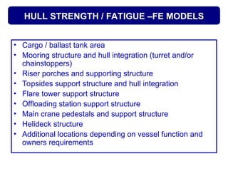
HULL STRENGTH /FATIGUE –FE MODELS
• Cargo / ballast tank area
• Mooring structure and hull integration (turret and/or
chainstoppers)
• Riser porches and supporting structure
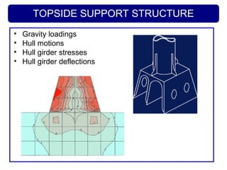
• Topsides support structure and hull integration
• Flare tower support structure
• Offloading station support structure
• Main crane pedestals and support structure
• Helideck structure
• Additional locations depending on vessel function and
owners requirements
9.
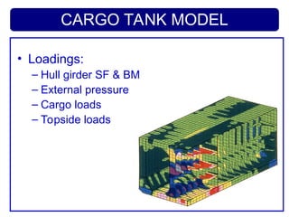
CARGO TANK MODEL
•Loadings:
– Hull girder SF & BM
– External pressure
– Cargo loads
– Topside loads
10.
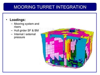
MOORING TURRET INTEGRATION
•Loadings:
– Mooring system and
risers
– Hull girder SF & BM
– Internal / external
pressure
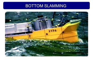
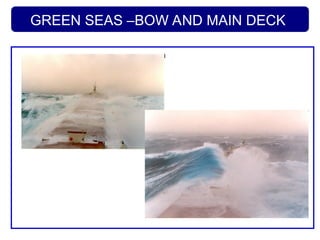
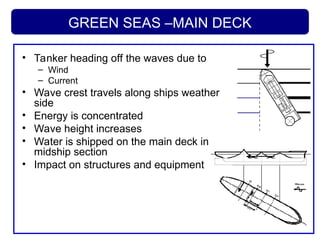
GREEN SEAS –MAINDECK
• Tanker heading off the waves due to
– Wind
– Current
• Wave crest travels along ships weather
side
• Energy is concentrated
• Wave height increases
• Water is shipped on the main deck in
midship section
• Impact on structures and equipment
16.
GREEN SEAS
• Factorsaffecting green seas:
– pitch response / wave length
– wave steepness
– wave height
– breaking waves
– loading condition (draft)
– bow shape
• Rules for ships incorporate allowances within
design heads for superstructures, deckhouses,
bulwarks and decks.
• Model testing advisable
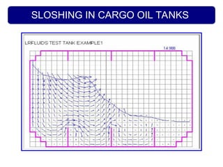
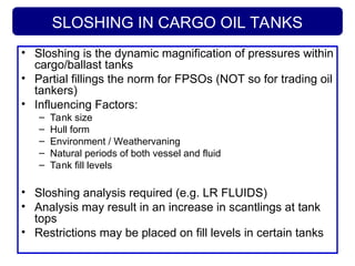
SLOSHING IN CARGOOIL TANKS
• Sloshing is the dynamic magnification of pressures within
cargo/ballast tanks
• Partial fillings the norm for FPSOs (NOT so for trading oil
tankers)
• Influencing Factors:
– Tank size
– Hull form
– Environment / Weathervaning
– Natural periods of both vessel and fluid
– Tank fill levels
• Sloshing analysis required (e.g. LR FLUIDS)
• Analysis may result in an increase in scantlings at tank
tops
• Restrictions may be placed on fill levels in certain tanks
FATIGUE –the problem
•The effect on metal of repeated cycles of stress.
• There is no obvious warning, a crack forms
without appreciable deformation of structure
making it difficult to detect the presence of
growing cracks.
• Fractures usually start from small nicks or
scratches or fillets which cause a localized
concentration of stress.
• Failure can be influenced by a number of factors
including size, shape and design of the
component, condition of the surface or operating
environment.
• Fatigue life of structural details need to be
assessed for FPSO
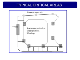
21.
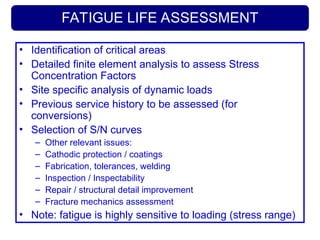
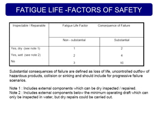
FATIGUE LIFE ASSESSMENT
•Identification of critical areas
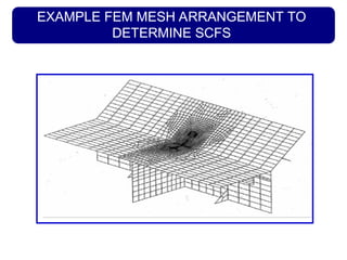
• Detailed finite element analysis to assess Stress
Concentration Factors
• Site specific analysis of dynamic loads
• Previous service history to be assessed (for
conversions)
• Selection of S/N curves
– Other relevant issues:
– Cathodic protection / coatings
– Fabrication, tolerances, welding
– Inspection / Inspectability
– Repair / structural detail improvement
– Fracture mechanics assessment
• Note: fatigue is highly sensitive to loading (stress range)
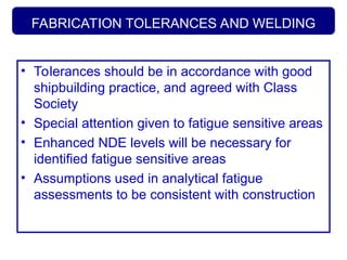
FABRICATION TOLERANCES ANDWELDING
• Tolerances should be in accordance with good
shipbuilding practice, and agreed with Class
Society
• Special attention given to fatigue sensitive areas
• Enhanced NDE levels will be necessary for
identified fatigue sensitive areas
• Assumptions used in analytical fatigue
assessments to be consistent with construction
IN SERVICE SURVEYPROGRAM
• Source :
– developed by the owner / operator against list
of surveyable items
– Survey plan to be approved by Class
• To address :
– Class requirements
– Regulatory requirements
– Overall hull structure configuration & critical
areas
28.
STRUCTURAL INSPECTION
• Carriedout on location
• Provides detection / monitoring capacity
• Annual, intermediate & major surveys
• Major survey (5 years or continuous)
• IWS in lieu of dry docking
• Internal survey considerations:
– cleaning & gas freeing
– access arrangements/safety
– Lighting / ventilation
– loading conditions for strength
29.
IN WATER SURVEYS
•Requirements for ‘OIWS’ notation
– Cathodic protection and high resistance paint
– Underwater marking
– Tank inspection conditions included in hull
girder analysis
– Venting/isolation arrangements for tank entry
– Arrangements considered for survey/change-
out of thrusters, sea chests, rudder bearing
etc.
30.
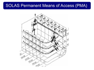
Permanent Means ofAccess (PMA)
• SOLAS requirements for newbuild
vessels
– All internal tanks
– Eliminate need for staging, rafting or rope
access
– Access for close up examination
– Utilise tanks structural members, or provide
dedicated arrangements
– Standards for ladders, handrails, etc
– Portable equipment may be used for some
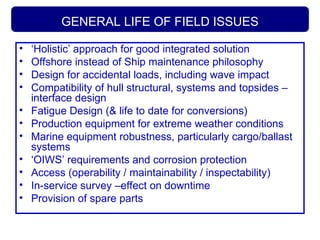
GENERAL LIFE OFFIELD ISSUES
• ‘Holistic’ approach for good integrated solution
• Offshore instead of Ship maintenance philosophy
• Design for accidental loads, including wave impact
• Compatibility of hull structural, systems and topsides –
interface design
• Fatigue Design (& life to date for conversions)
• Production equipment for extreme weather conditions
• Marine equipment robustness, particularly cargo/ballast
systems
• ‘OIWS’ requirements and corrosion protection
• Access (operability / maintainability / inspectability)
• In-service survey –effect on downtime
• Provision of spare parts
33.
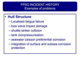
FPSO INCIDENT HISTORY
Examplesof problems
• Hull Structure
– Localised fatigue failure
– bow wave impact damage
– shuttle tanker collision
– tank overpressurisation
– seawater caisson preferential corrosion
– integration of surface and subsea corrosion
protection
FPSO RULE AMENDMENTSFOR FORE END
STRUCTURES
• Basis -Ship Rule requirements using min.
service speed 12 -15 knots
• Site specific assessments required where
expected to be more severe
• Model test measurements of impact pressures
recommended
• Integrated structural design approach to be
adopted using direct calculation methods (LR
Rules for permissible stress requirements)


![[Vanbanphapluat.co] tcvn12012 2017](https://cdn.slidesharecdn.com/ss_thumbnails/vanbanphapluat-181015040253-thumbnail.jpg?width=640&height=640&fit=bounds)


