Downloaded 36 times
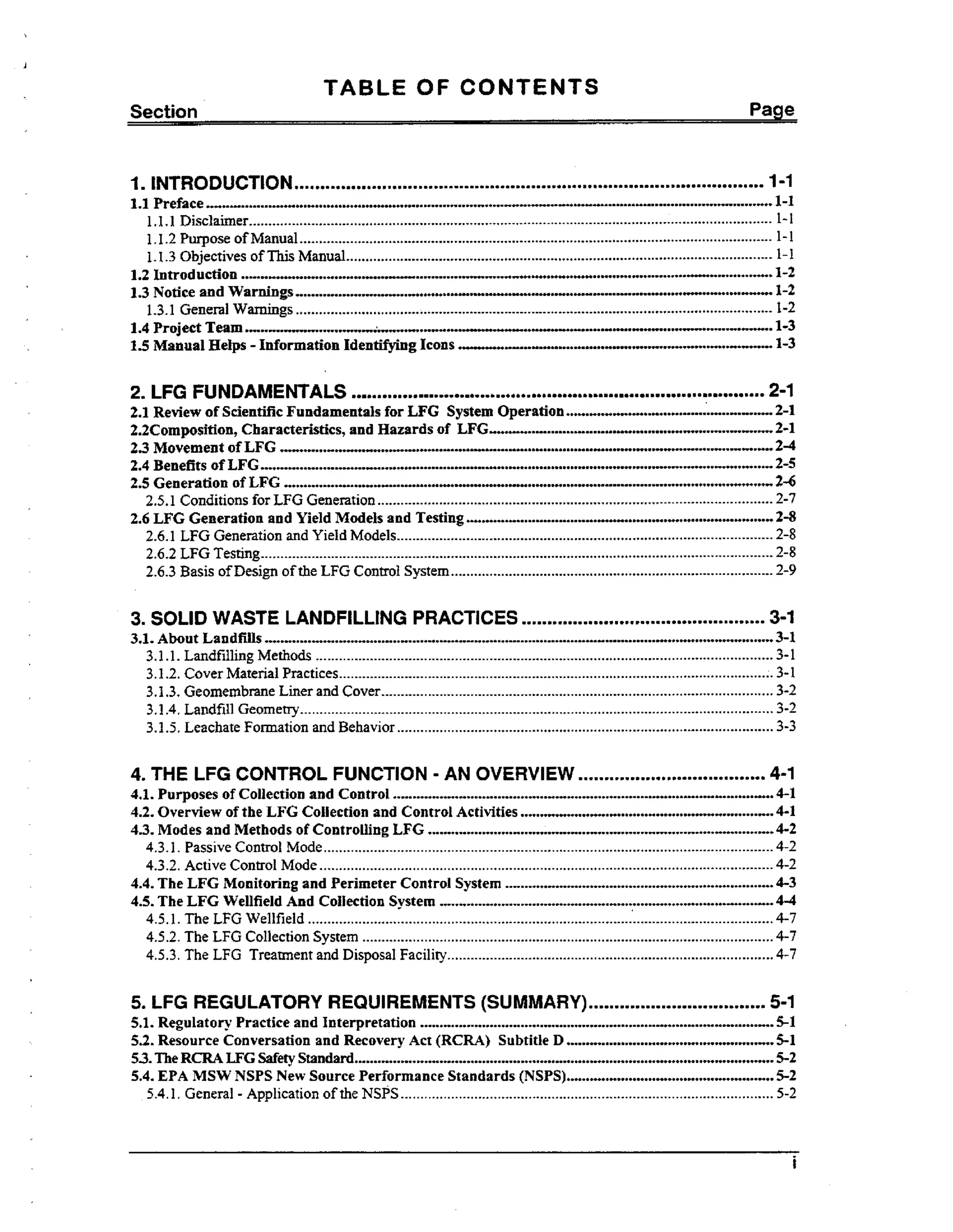

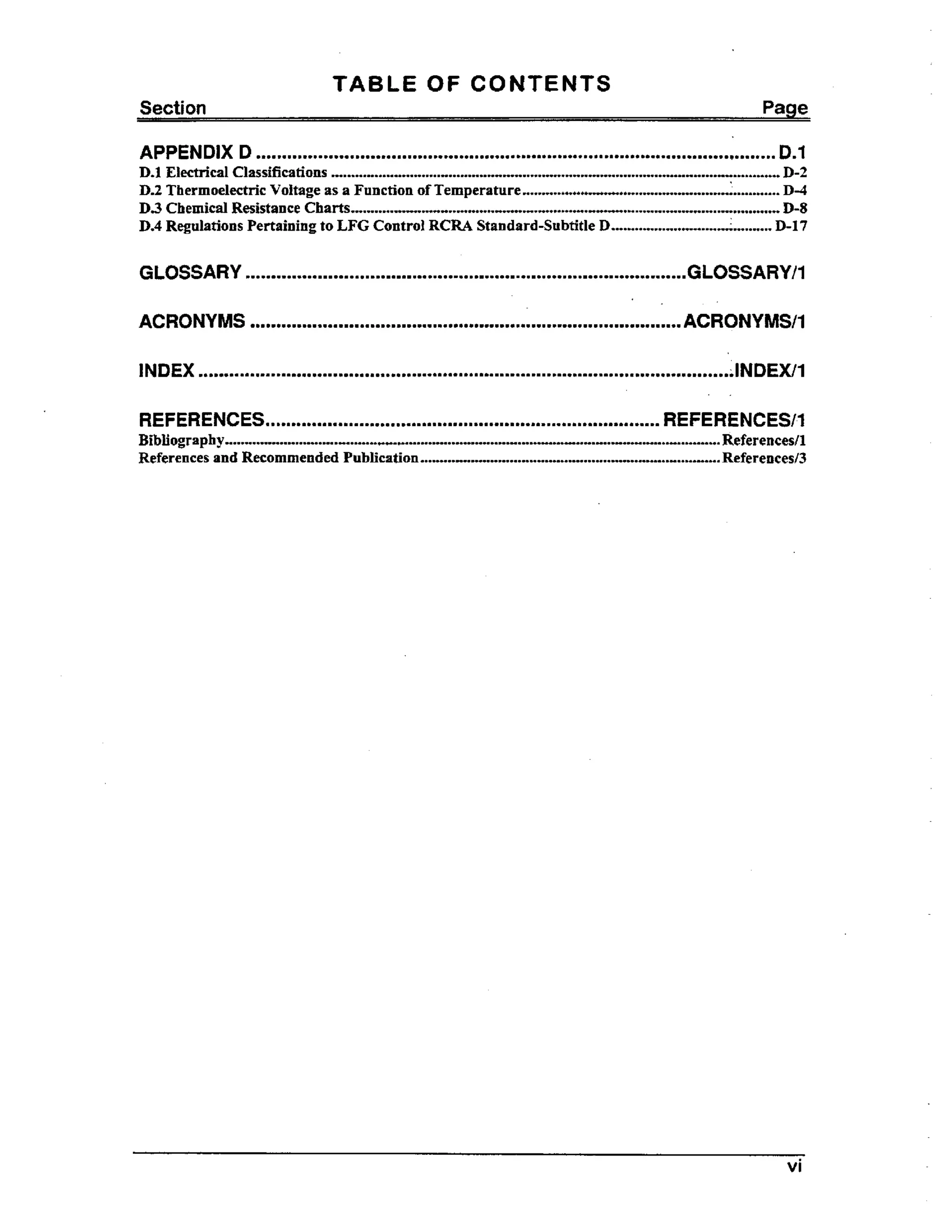


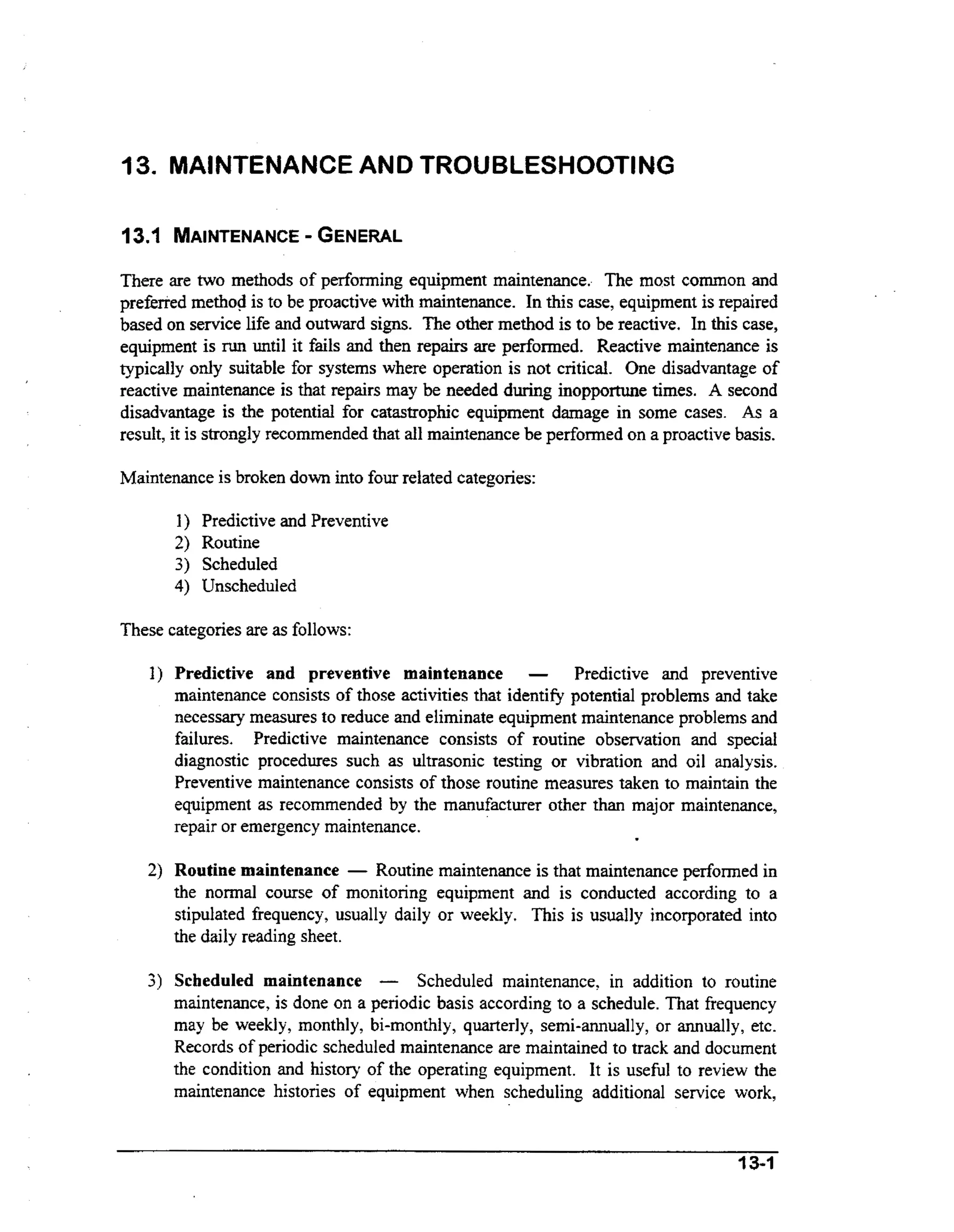


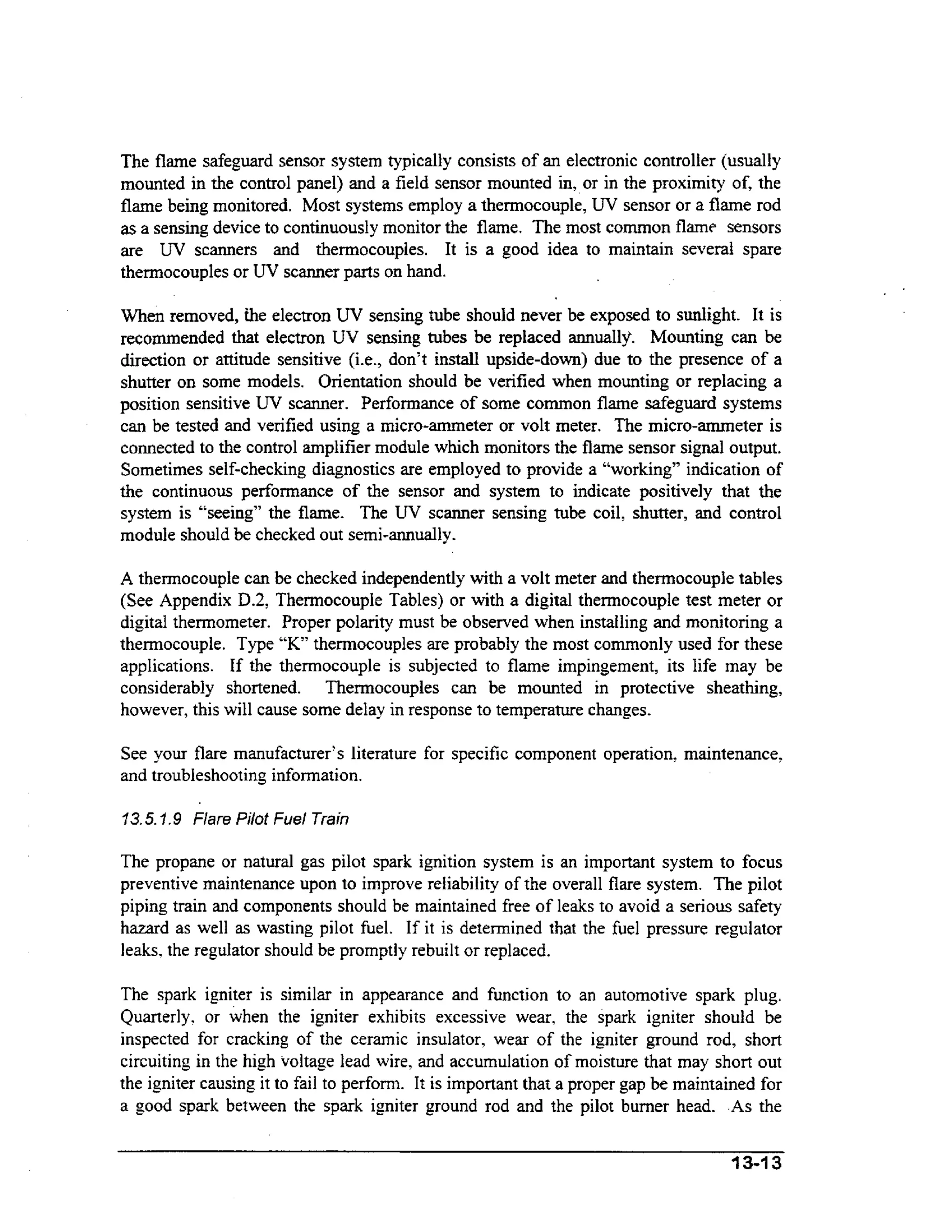


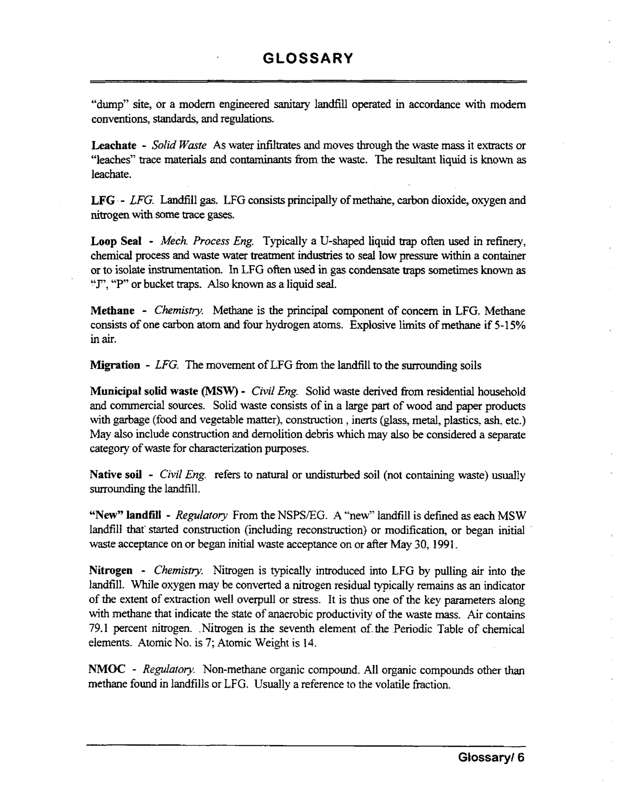
![(i) Soil conditions;
(ii) The hydrogeologic conditions surrounding the facility;
(iii) The hydraulic conditions surrounding the facility; and
(iv) The location of facility structures and property boundaries.
(2) The minimum frequency of monitoring shall be quarterly.
(c) If methane gas levels exceeding the hnits specified in paragraph (a) of this section are detected,
the’owner or operator m s :
ut
(1) Immediately take a 1 necessary steps to ensure protection of human health and notify the State
1
Director;
L
(2) Within seven days of detection, place i the operating record the methane gas levels detected and
n
description of steps taken to protect human health; and
(3) Within 60 days of detection, implement a remediation plan for the methane gas releases, place a
copy of the plan in the operating record, and notify the State Director that the plan has been
implemented. The plan shall describe the nature and extent of the problem and the proposed remedy.
(4) The Director of an approved State may establish alternative schedules for demonstrating
compliance with paragraphs (c) (2) and (3) of this section.
[Part258.28 Explosive gases control. continued]
(d) For purposes of this section, Zower explosive Iimit means the lowest percent by volume of a
mixture of explosive gases in air that will propagate a flame at 25 deg. C and atmospheric pressure.
5 258.24
Air criteria.
(a) Owners and operators of all MSWLFs must ensure that the units not violate any applicable
requirements developed under a State Implementation PIan (SIP) approved or promulgated by the
Administrator pursuant to section 110 of the Clean Air Act, as amended.
(b) Open burning of solid waste except the infrequent burning agricultural wastes, silvicultural
wastes, landclearing debris diseased trees, or debris from emergency cleanup operations, is prohibited at
a11 MSWLF units.
258.28 Liquids restrictions.
(a) Bulk or noncontainerized liquid waste may not be placed in MSWLF units unless:
(1) the waste is household waste other than septic waste; or
D-I 8](https://image.slidesharecdn.com/230701-131101182926-phpapp01/75/23070-1-243-2048.jpg)
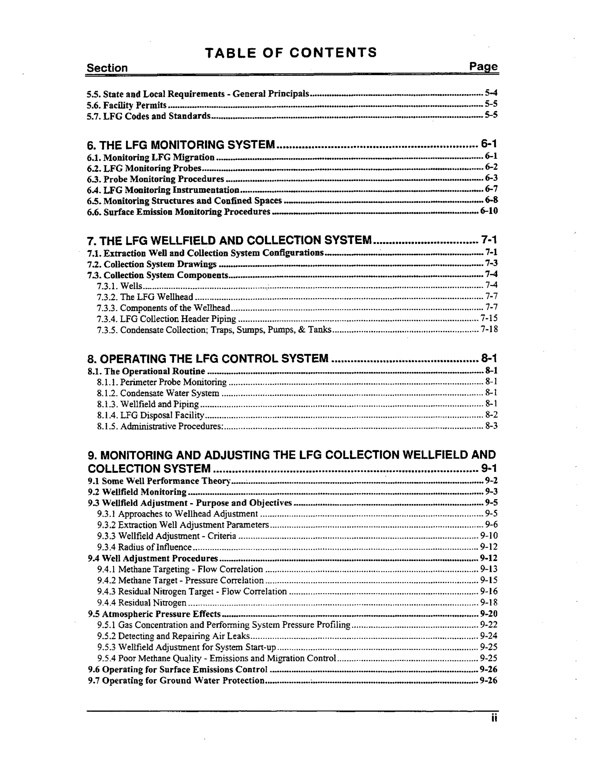
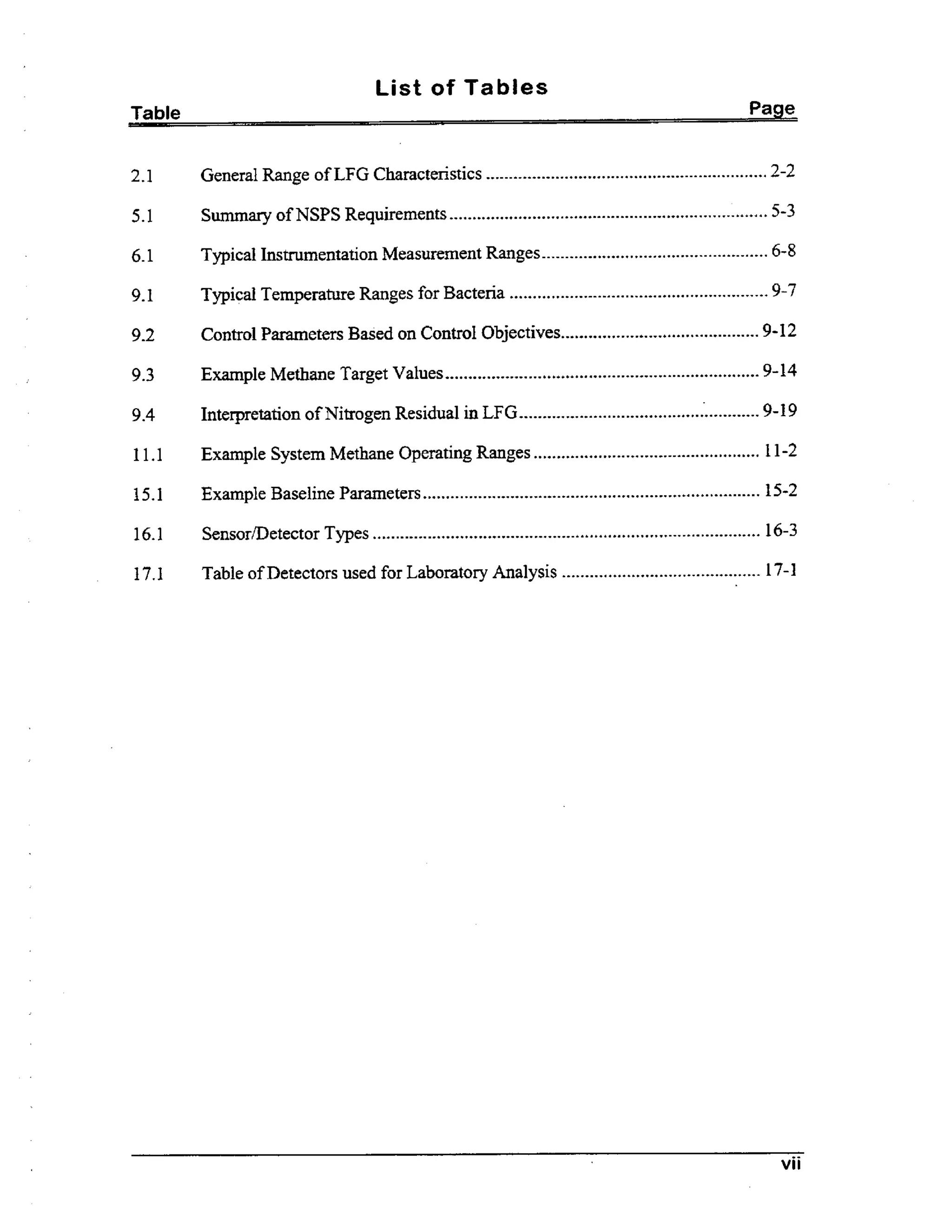
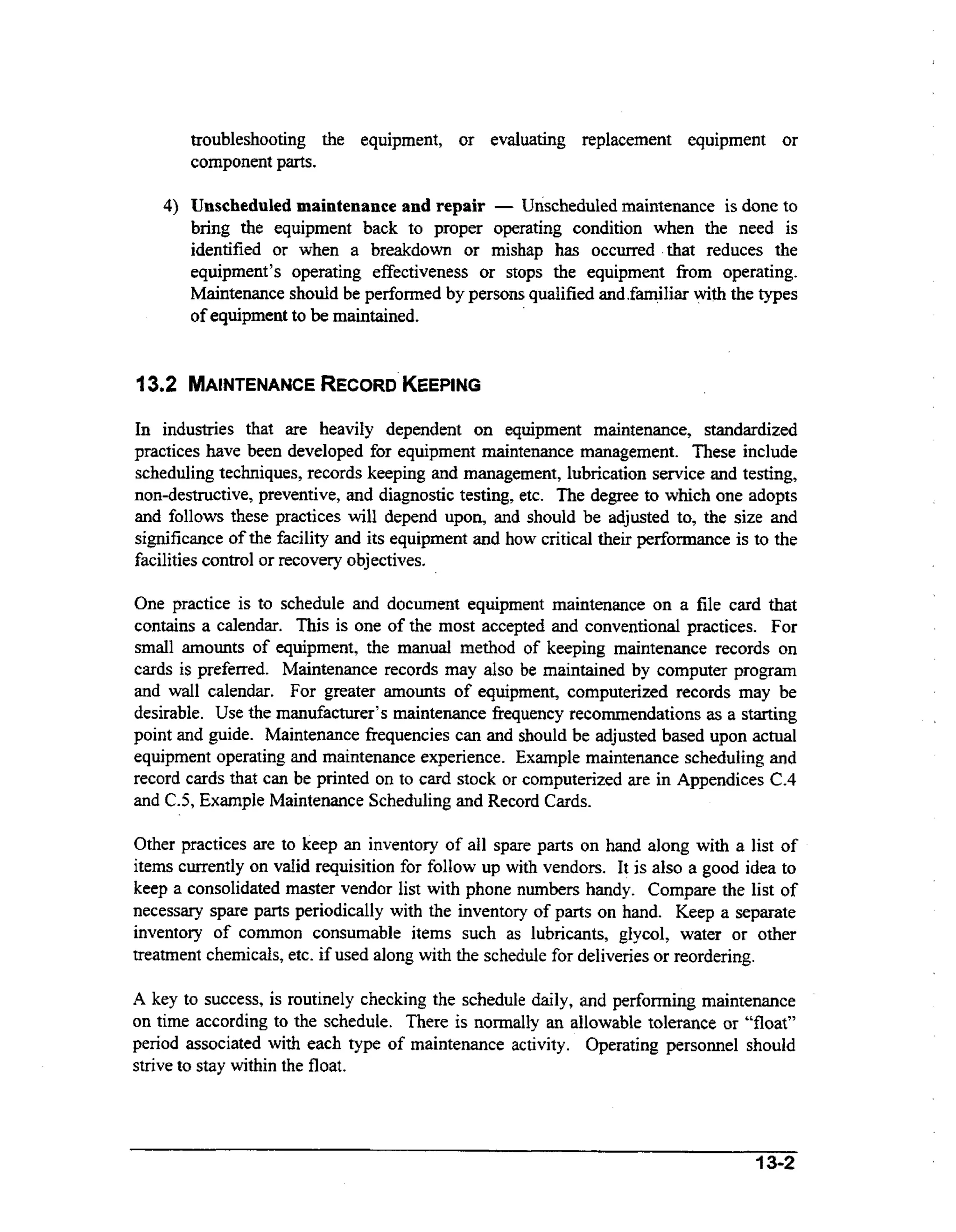
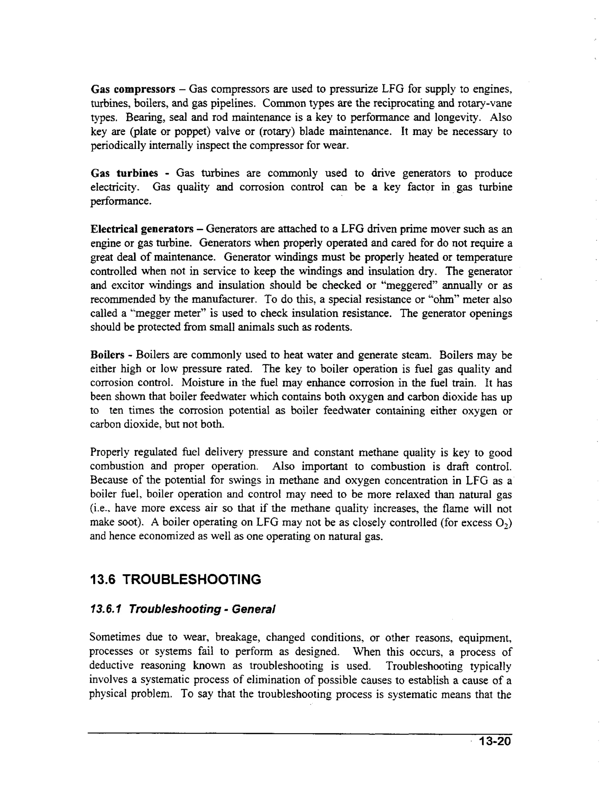
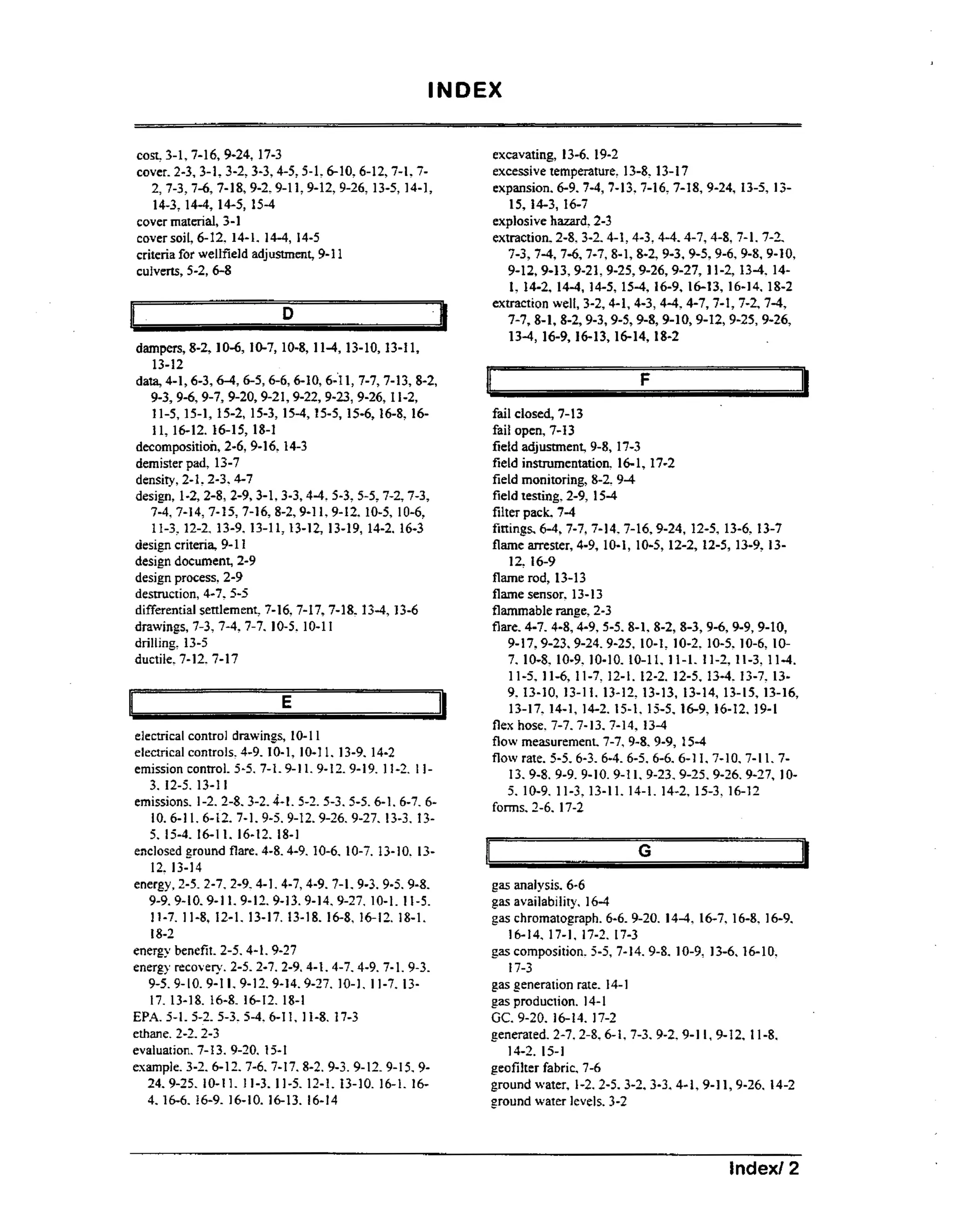
![APPENDIX D.4
(2) The waste is leachate or gas condensate derived fiom the MSWLF unit and the MSWLF unit,
whether it is a new or existing MSWLF, or lateral expansion, is designed with a composite liner and
n
leachate collection system as described i 8 258.40(a)(2) of this part. The owner or operator must place
the demonstration in the operating record and notify the State Director that it has been placed in the
operating record.
(b) Containersholding liquid waste may not be placed in a MSWLF unit unless:
(1) The cofitainer is a small container similar in size to that is nckmlly found in household waste;
(2) The container is designed to hold liquids for use other than storage; or
(3) The waste is household waste.
[Part258.28 Liquids restrictions. continued]
(c) For purposes of this section:
(1) Liquid waste means any waste material that is determined to contain “free liquids” as defined by
Method 9095 (Paint Filter Liquids Test), as described in “Test Methods for Evaluating Solid Wastes,
PhysicaVChemical Methods” (EPA Pub. No.SW-846).
(2) Gas condensate means the liquid generated as a result of gas recovery process(es) at the MSWLF
unit.
*****************************
Source: 40 CFR Parts 257 and 258.
D-?9](https://image.slidesharecdn.com/230701-131101182926-phpapp01/75/23070-1-244-2048.jpg)


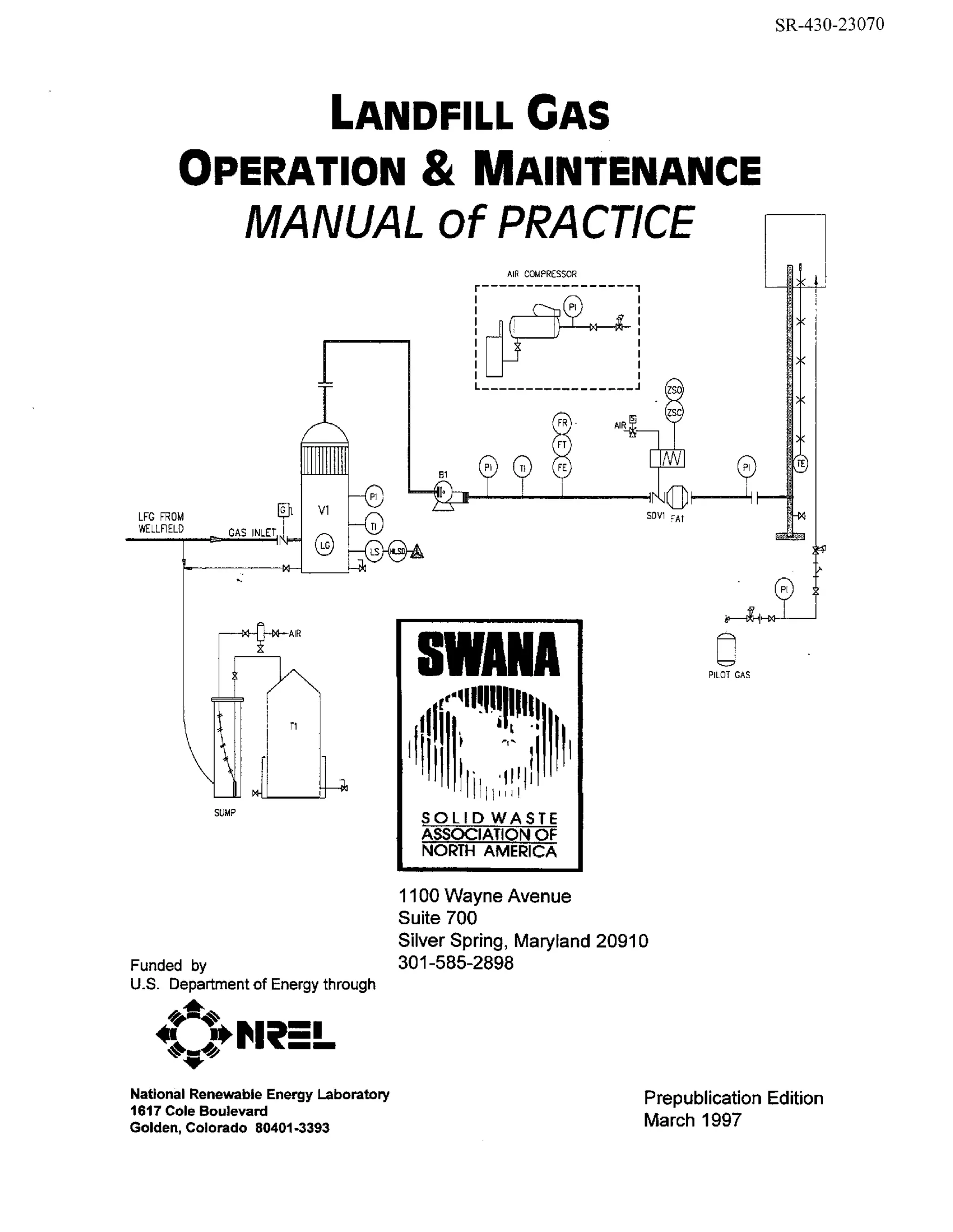
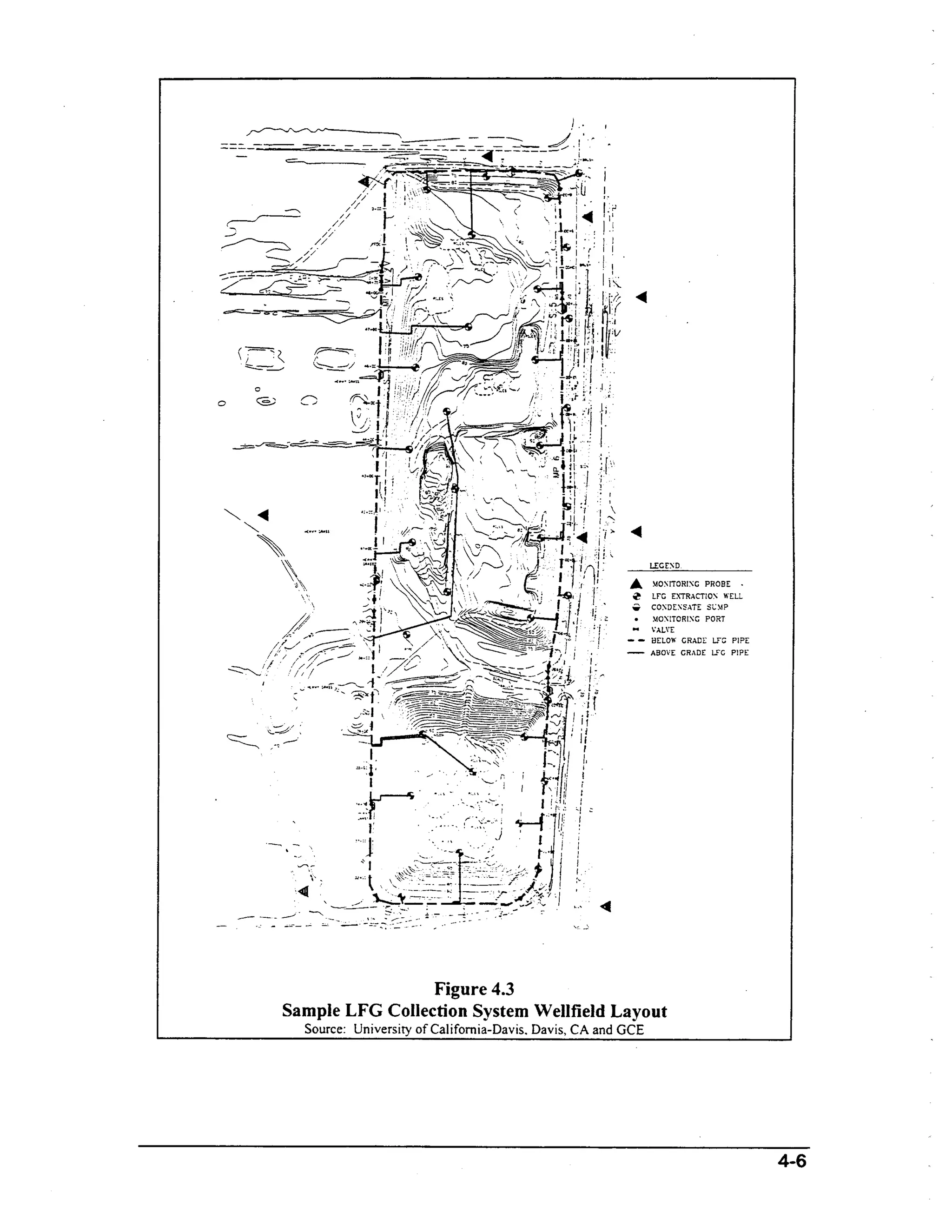
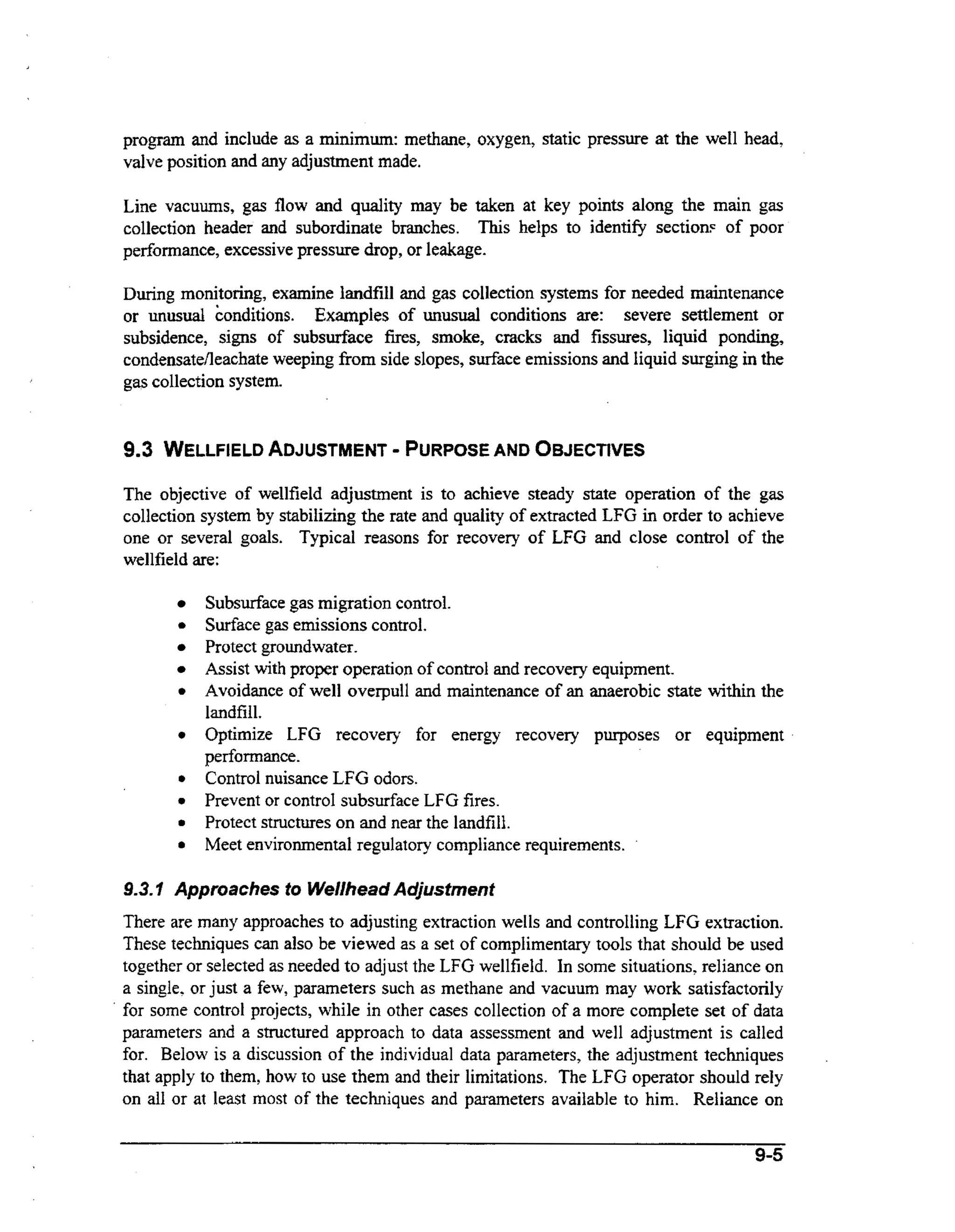
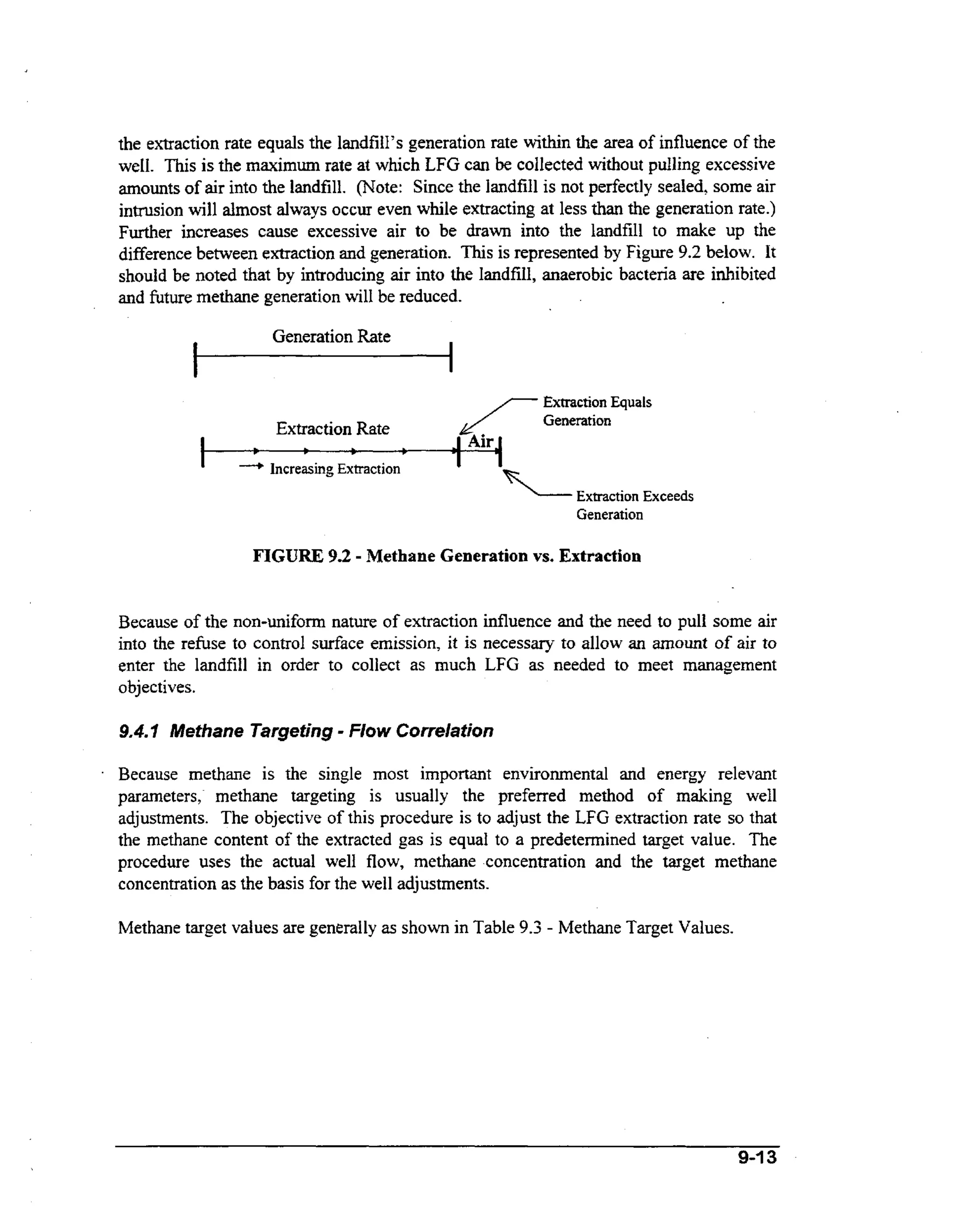
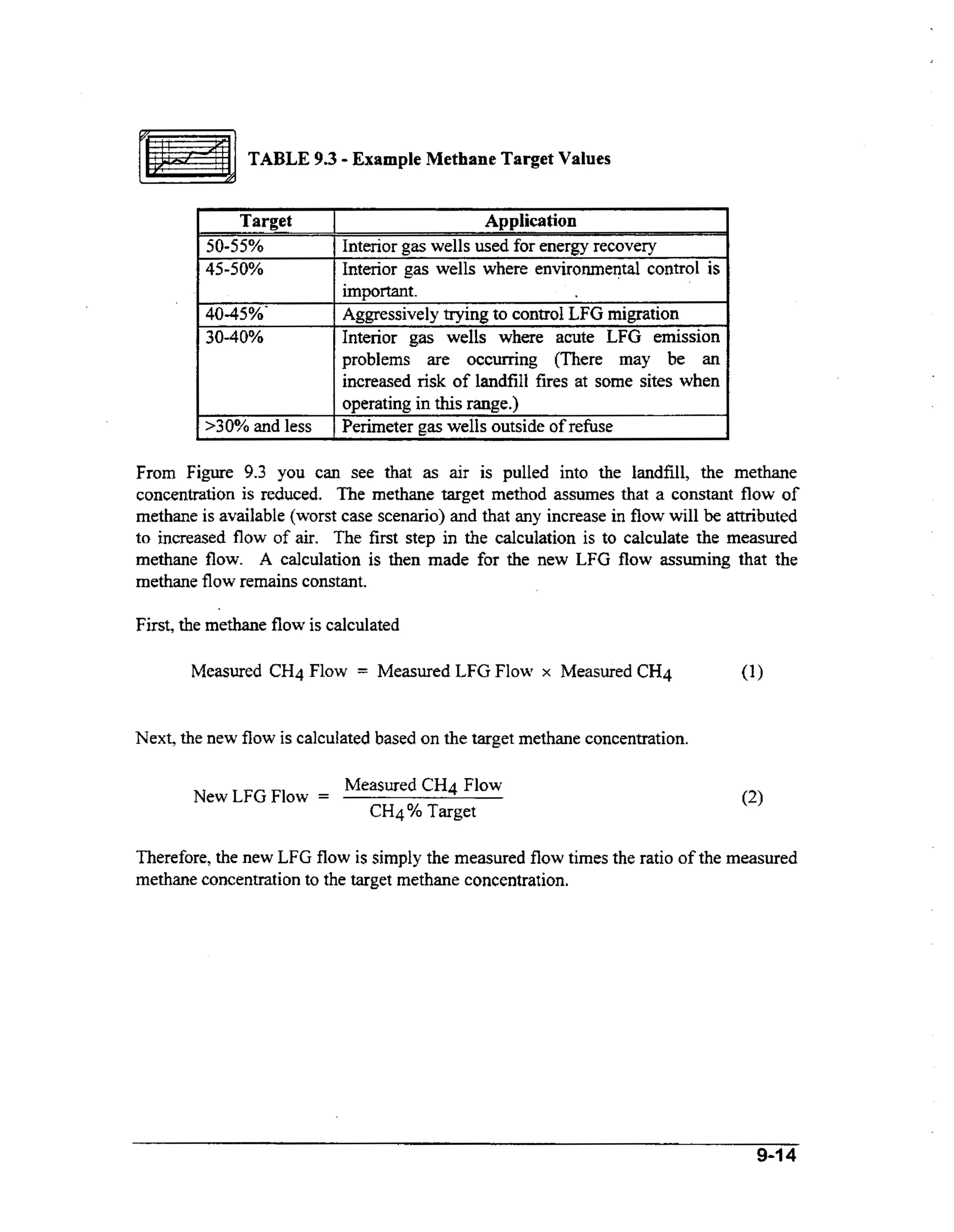
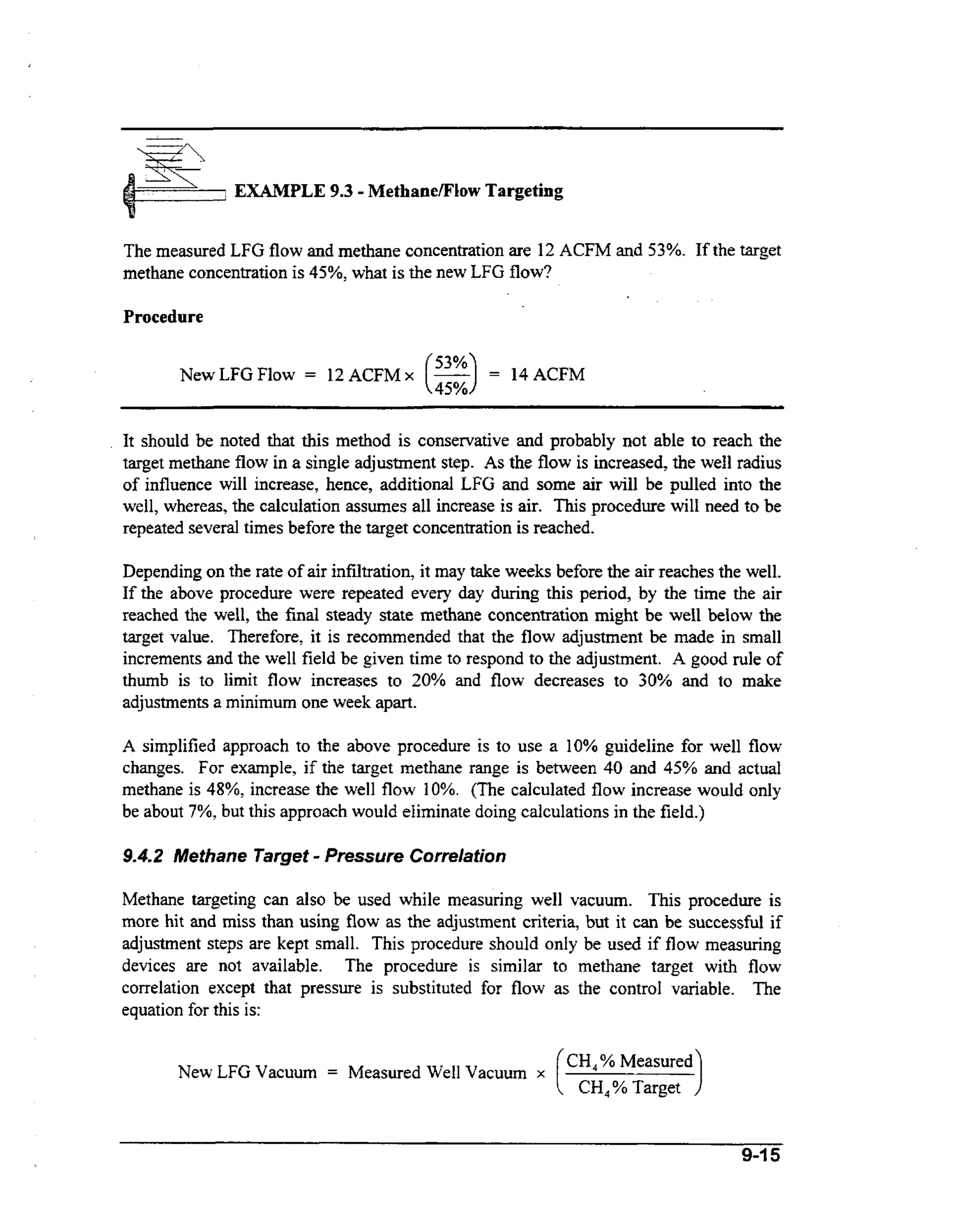
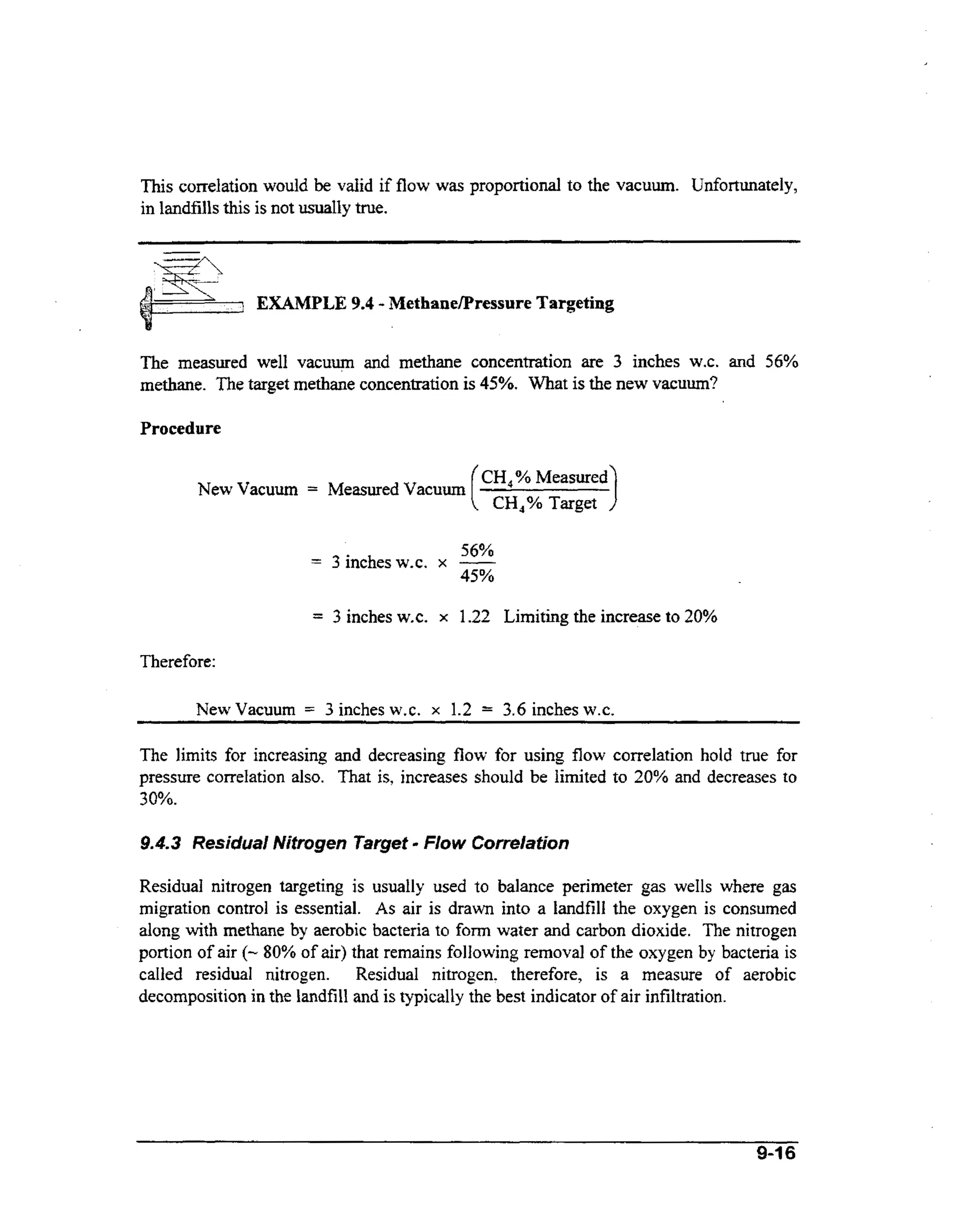
This document provides guidance on landfill gas (LFG) system operation and maintenance. It discusses the fundamentals of LFG including its composition, generation within landfills, and methods for testing and modeling LFG production. It also describes common landfilling practices and regulations regarding LFG collection. The purpose of LFG systems is to collect and control gas to protect human health and the environment. These systems typically include a wellfield to extract gas, collection pipes to convey it to a central location, and treatment equipment to process the gas before disposal or energy recovery.


![Developer manual gs-cer[1]](https://cdn.slidesharecdn.com/ss_thumbnails/developermanualgs-cer1-131228010048-phpapp01-thumbnail.jpg?width=640&height=640&fit=bounds)


![Handbook esp[1]](https://cdn.slidesharecdn.com/ss_thumbnails/handbookesp1-140515130349-phpapp01-thumbnail.jpg?width=640&height=640&fit=bounds)


![Emilio%20 godoy %20good%20bye%20kyoto_expansión_1[1]](https://cdn.slidesharecdn.com/ss_thumbnails/emilio20godoy20good20bye20kyotoexpansin11-131228005156-phpapp01-thumbnail.jpg?width=640&height=640&fit=bounds)


![Coded Agents – with UiPath SDK + LangGraph [Virtual Hands-on Workshop]](https://cdn.slidesharecdn.com/ss_thumbnails/codedagentsdeck-251215155422-5497c599-thumbnail.jpg?width=640&height=640&fit=bounds)


