This document provides guidance on stormwater detention storage design. It discusses the types of detention (dry, extended dry, wet), factors to consider in detention storage design like location and size, and methods for estimating preliminary detention storage volumes. The key methods discussed are the rational hydrograph method, Wycoff and Singh method, and the NRCS TR-55 method, which are used to provide initial estimates of storage needs based on pre-development and post-development peak flows and hydrologic parameters. Final detention storage design requires simultaneously sizing the storage volume and outlet structures using storage routing procedures.


![Iowa Stormwater Management Manual
6 Version 2; December 5, 2008
Table 1: Worksheet for planning estimates of required storage volume
Required for Method
Parameter Symbol Units Value
1 2 3 4
Drainage Area Am Acres X X X X
Runoff depth – before Qb Inches X
Runoff depth – after Qa Inches X X X X
Peak discharge – before Qpb ft3
/sec X X X
Peak discharge – after Qpa ft3
/sec X X X
Discharge ratio 1
α X X X
Time of concentration - before tcb hours X
Time of Concentration - after tca hours
Time to peak - before tpb hours
Time to peak - after tpa hours
Storage volume/runoff volume Rv
Hydrograph time base - after Tb hours
Time ratio 2
γ
1
α = qpb/qpa
2
γ = tpb/tpa or tcb/tca (where tp = tc)
3
Vs = volume of storage in inches
4
Rv = Vs/Qa (Note: Q = Vr in inches)
5 Vst = VsAm/12 [=] acre-ft
Method Computational Form Rv
Vs
(inch)
Vst
(ac-ft)
1
Rational
hydrograph
Vst = .08264tcb(qpa-qpb)
2
Wycoff and
Singh
Vs = 1.29Qa(1- α)0.753
(Tb/tpa)-0.411
3
NRCS TR55
(Type II)
Rv = 0.682 -1.43 α + 1.64 α2
– 0.805 α3
4
LID
Hydrologic
method
Vs = Qa - Qb
Source: Adapted from McCuen, 1989
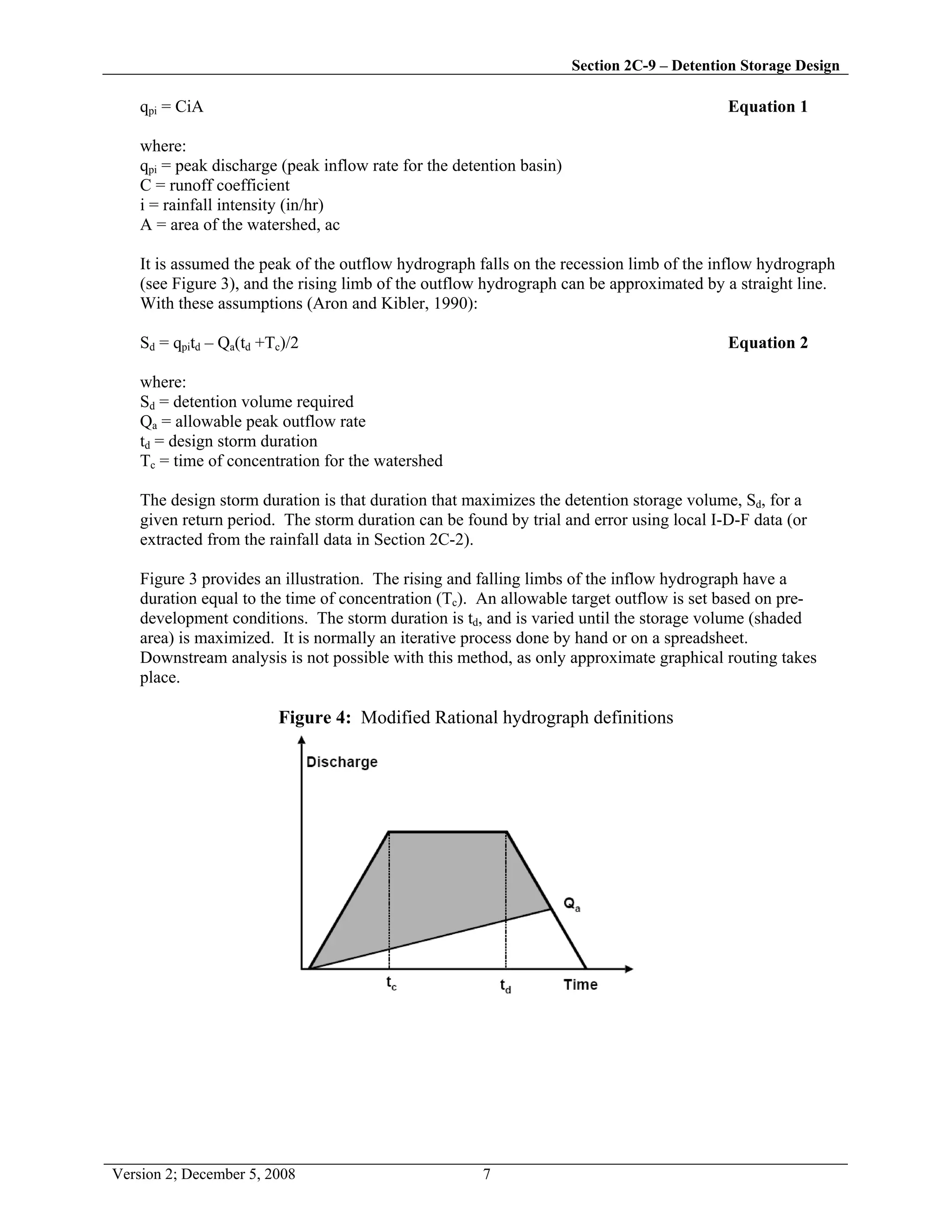
E. Modified Rational method
The Rational method was originally intended for the peak discharge design only. The runoff
coefficients represent the ratio of the peak discharge per unit area to average intensity of a storm that
has the same return period. The runoff volume was not considered in developing the Rational
formula, and the Rational method was not meant for detention basin design. However, a modified
Rational method, actually an extension of the conventional Rational method, has been used in the past
for preliminary sizing of detention basins. The method is included in this manual with a restriction to
drainage areas of less than 20 acres. The Modified Rational method uses the peak flow calculating
capability of the Rational method, paired with assumptions about the inflow and outflow hydrographs
to compute an approximation of storage volumes for simple detention calculations. There are many
variations on the approach.
The basic approach assumes the stormwater runoff hydrograph (detention basin inflow hydrograph)
for the design storm is trapezoidal in shape. The peak runoff rate is calculated using the rational
formula](https://image.slidesharecdn.com/2c-9detentionstoragedesign-150720013442-lva1-app6892/75/2-c-9detentionstoragedesign-6-2048.jpg)