
Recommended
More Related Content
Similar to 190180668-Actix-Cellrefs.pdf
Similar to 190180668-Actix-Cellrefs.pdf (20)
Recently uploaded
Recently uploaded (20)
190180668-Actix-Cellrefs.pdf
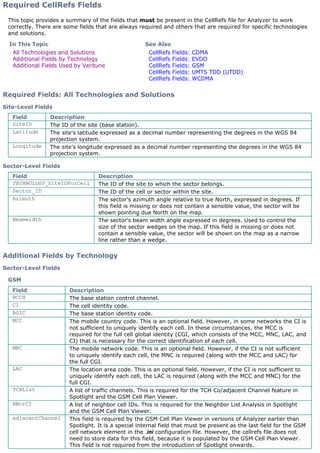
- 1. Required CellRefs Fields This topic provides a summary of the fields that must be present in the CellRefs file for Analyzer to work correctly. There are some fields that are always required and others that are required for specific technologies and solutions. Required Fields: All Technologies and Solutions Site-Level Fields Sector-Level Fields Additional Fields by Technology Sector-Level Fields GSM In This Topic See Also All Technologies and Solutions Additional Fields by Technology Additional Fields Used by Veritune CellRefs Fields: CDMA CellRefs Fields: EVDO CellRefs Fields: GSM CellRefs Fields: UMTS TDD (UTDD) CellRefs Fields: WCDMA Field Description SiteID The ID of the site (base station). Latitude The site's latitude expressed as a decimal number representing the degrees in the WGS 84 projection system. Longitude The site's longitude expressed as a decimal number representing the degrees in the WGS 84 projection system. Field Description TECHNOLOGY_SiteIDForCell The ID of the site to which the sector belongs. Sector_ID The ID of the cell or sector within the site. Azimuth The sector's azimuth angle relative to true North, expressed in degrees. If this field is missing or does not contain a sensible value, the sector will be shown pointing due North on the map. Beamwidth The sector's beam width angle expressed in degrees. Used to control the size of the sector wedges on the map. If this field is missing or does not contain a sensible value, the sector will be shown on the map as a narrow line rather than a wedge. Field Description BCCH The base station control channel. CI The cell identity code. BSIC The base station identity code. MCC The mobile country code. This is an optional field. However, in some networks the CI is not sufficient to uniquely identify each cell. In these circumstances, the MCC is required for the full cell global identity (CGI, which consists of the MCC, MNC, LAC, and CI) that is necessary for the correct identification of each cell. MNC The mobile network code. This is an optional field. However, if the CI is not sufficient to uniquely identify each cell, the MNC is required (along with the MCC and LAC) for the full CGI. LAC The location area code. This is an optional field. However, if the CI is not sufficient to uniquely identify each cell, the LAC is required (along with the MCC and MNC) for the full CGI. TCHList A list of traffic channels. This is required for the TCH Co/adjacent Channel feature in Spotlight and the GSM Cell Plan Viewer. NBorCI A list of neighbor cell IDs. This is required for the Neighbor List Analysis in Spotlight and the GSM Cell Plan Viewer. adjacentChannel This field is required by the GSM Cell Plan Viewer in versions of Analyzer earlier than Spotlight. It is a special internal field that must be present as the last field for the GSM cell network element in the .ini configuration file. However, the cellrefs file does not need to store data for this field, because it is populated by the GSM Cell Plan Viewer. This field is not required from the introduction of Spotlight onwards.
- 2. CDMA/EV-DO UMTS UMTS TDD (UTDD) iDEN IS 136/IS 54 Additional Fields Used by Veritune The following table lists the additional sector-level fields used by Veritune. Except where stated otherwise, these fields are required. Field Description PN The pseudo noise code for the sector. Field Description SC The sector's scrambling code. WCDMANeighborList This is an array field is required only by the 3G missing neighbor analysis to store the scrambling (SC) codes of the 3G neighbors. Although this field must be present on the WCDMA_Cell network element, it does not need to store data, because the 3G missing neighbor analysis will automatically suggest neighbors. If this field does store data, the analysis will suggest cells for removal when they do not meet the defined criteria. GSMNeighborList This is an array field that is required only by the 3G-2G missing neighbor analysis to store the cell identity (CI) codes of the 2G neighbors. Note that these must match CI codes of GSM sector elements within the CellRefs file. Although this field must be present on the WCDMA_Cell network element, it does not need to store data, because the 3G-2G missing neighbor analysis will automatically suggest neighbors. If this field does store data, the analysis will suggest cells for removal when they do not meet the defined criteria. Field Description Toffset The time offset for the sector. UARFCN The UTRA absolute radio frequency channel number. Field Description CCCH Common control channel. Can be used to color the sector wedges. Color_Codes A list of color codes (SAT and DVCCs) that match the entries in the Traffic_Channels field. Used for determining likely serving and neighbor cells. Field Description Color_Codes A list of color codes (SAT and DVCCs) that match the entries in the Traffic_Channels field. Used for determining likely serving and neighbor cells. Technology Field Description All Antenna_key A unique identifier for the antenna mask in use on the site. The antenna mask identifies a specific electrical downtilt configuration for a particular antenna type. This key must correspond to a key in the antenna pattern database. Height Height in meters of the base station antenna above ground level. Tilt The tilt of the antenna measured in degrees. This is positive for downtilt and negative for uptilt. GSM EIRP This optional field stores outward power of the sector in dBm. If this field is present, Veritune adjusts it when you enter a value in the Relative Power box. If this field is not present, Veritune adjusts the measured power value instead. UMTS PA Power The maximum PA output power in dBm. Integer. Pilot_Power The CPICH power in dBm. Integer. Sync_Power The combined P-SCH and S_SCH power in dBm. Integer. Other_Common_Powers The combined power for other common downlink channels in dBm. Integer. EV-DO CDMA_Freq This optional field indicates the frequency in MHz in multi- frequency network configurations where PN varies with frequency.
- 3. Technology-Specific Information CellRefs Fields: CDMA CellRefs Fields: EVDO CellRefs Fields: GSM CellRefs Fields: UMTS TDD (UTDD) CellRefs Fields: WCDMA See Also Structure of the CellRefs File CellRefs Preferences Veritune Preferences Adding New Fields to the CellRefs File Lines to Cells CellRefs History CellRefs Limits Send feedback on this topic If this field is absent, all frequencies are assumed. Integer. EIRP This optional field stores outward power of the sector in dBm. If this field is present, Veritune adjusts it when you enter a value in the Relative Power box. If this field is not present, Veritune adjusts the measured power value instead. CDMA CDMA_Freq This optional field indicates the frequency in MHz in multi- frequency network configurations where PN varies with frequency. If this field is absent, all frequencies are assumed. Integer. EIRP This optional field stores outward power of the sector in dBm. If this field is present, Veritune adjusts it when you enter a value in the Relative Power box. If this field is not present, Veritune adjusts the measured power value instead. PctPilot Percentage of power allocated to pilot channel. Integer. PctTraffic Percentage of power allocated to traffic channels. Integer. PctPaging Percentage of power allocated to paging channel. Integer. PctSync Percentage of power allocated to synchronization channels. Integer.
- 4. Structure of the CellRefs File Contents Introduction The DefNetworkData.ini file The CellRefs file Introduction Network configuration information (such as the names, IDs, and locations of the cell sites, etc.) is stored in a text file that is called the CellRefs file. This topic provides information about the structure of this file and the configuration file (called DefNetworkData.ini), which defines its structure and format. You set the location of the CellRefs file in the Preferences dialog box. See CellRefs Preferences for more information. The cellrefs file is a text file that stores information about actual physical network elements. The first line of the file must be as follows: ; #NetworkData - datafile Each subsequent line in the file stores information about an individual network element (such as a cell or site). The information that is stored for each network element must correspond to the definition specified for that type of network element in the DefNetworkData.ini file. The DefNetworkData.ini file The DefNetworkData.ini file is a configuration file that defines the structure and format of the information in the CellRefs files. The default DefNetworkData.ini file is located in the Program FilesActixAnalyzerBin folder. However, you can override the default file with a custom one—for example, if you want to store additional data about the network elements. This is done by creating a custom configuration file with the same name as the cellrefs file but with an .ini filename extension and placing it in the same folder as the cellrefs file. (For example, if the cellrefs file is called cellrefs.txt, the custom configuration file must be called cellrefs.ini.) Note that the default configuration file is totally ignored when a custom configuration file is present. The DefNetworkData.ini file contains two key sections—[Network Elements] and [Fields] and one or more additional sections defining the root object in the hierarchy of net elements for a technology. The default DefNetworkData.ini file contains one of these elements, [GSM_MSC]. [Network Elements]. This section defines the different types of network element and the fields that are stored for each one using the Network_Element_Name=Field1 Field2 Field3... syntax. For example: [Network Elements] CDMA_Site=Site_Name SiteID Latitude Longitude CDMA_Cell=CDMA_SiteIDForCell Sector_ID Azimuth Beamwidth EIRP PN MCC SID NID BID PctPilot PctTraf GSM_MSC=ID MSCName GSM_BSC=ID MSCID BSCName GSM_Site=Site_Name SiteID Latitude Longitude GSM_Cell=GSM_SiteIDForCell Sector_ID Azimuth Beamwidth EIRP BCCH MCC MNC LAC CI BSIC BSCID Face_D . . . [Fields]. This section defines the properties of each field, including: The format group (such as string, integer, degrees, or percentage) to be used for the data in the field. Format groups specify the data type and control how the information is formatted (for example, when it is displayed in the Map view). The format group can also be used to define valid values to be used to validate the data when it is imported. Whether the field is Required (must be present) or Key (must be present and unique). Whether the field is an array field, which means that the field can contain a variable-length list of values (such as a neighbor list). These fields are specified using the array keyword, as shown for the CDMANeighborList field below. If the field maps one network element to another, the related field is defined using the Ref:NetworkElement:Field:RelationTypeToOther#RelationToMe syntax. RelationTypeToOther specifies the relationship between the network element and the linked object (typical examples are Parent and CellSite). RelationToMe specifies the reverse relationship (for example, Child and Cell). In the snippet from the [Network Elements] section shown above, the CDMA_SiteIDForCell field has been highlighted. Below is a snippet from the [Fields] section, in which the same field has been highlighted. Notice that the Ref keyword has been used to specify that this field is linked to the SiteID field in the CDMA_Site
- 5. network element. [Fields] Test=array:integer GSM_SiteIDForCell=Ref:GSM_Site:SiteID:CellSite#Cell:key CDMA_SiteIDForCell=Ref:CDMA_Site:SiteID:CellSite#Cell:key CDMA1xEVDO_SiteIDForCell=Ref:CDMA1xEVDO_Site:SiteID:CellSite#Cell:key IS136_SiteIDForCell=Ref:IS-54/IS-136_Site:SiteID:CellSite#Cell:key AMPS_SiteIDForCell=Ref:AMPS_Site:SiteID:CellSite#Cell:key IDEN_SiteIDForCell=Ref:IDEN_Site:SiteID:CellSite#Cell:key TETRA_SiteIDForCell=Ref:TETRA_Site:SiteID:CellSite#Cell:key WCDMA_SiteIDForCell=Ref:WCDMA_Site:SiteID:CellSite#Cell:key MSCID=Ref:GSM_MSC:ID:Parent#Child BSCID=Ref:GSM_BSC:ID:Parent#Child Site_Name=Site SiteID=string:key Latitude=Degrees:required Longitude=Degrees:required . . . CDMANeighborList=array:integer . . . [GSM_MSC]. This section specifies that the GSM_MSC network element is the root element in the hierarchy of GSM network elements. Custom configuration files might contain an equivalent section for other technologies. [GSM_MSC] RootObject=yes Entire default DefNetworkData.ini file The CellRefs file The cellrefs file is a tab-delimited text file that stores information about actual physical network elements. With the exception of the first line, each line in the file stores information about an individual network element (such as a cell or site). The information that is stored for each network element must correspond to the definition specified for that type of network element in the DefNetworkData.ini file (which is described above). This means that if a field is not used, an additional tab must be entered to retain the mapping of the subsequent fields. (However, this is not necessary for unused fields at the end of the line.) Here is a snippet of a cellrefs file: ; #NetworkData - datafile GSM_Cell S_1 A 0 92 45 592 0 0 5004 40121 52 GSM_Cell S_1 B 130 92 45 599 0 0 5004 40122 52 GSM_Cell S_1 C 240 92 45 606 0 0 5004 40123 52 . . . GSM_Site 91MOO1 91MOO 99.94108333 99.790222222 GSM_Site 91MLL1 91MLL 99.99913889 99.803555556 GSM_Site 91GTZ1 91GTZ 99.02313889 99.699555556 . . . If we refer to the definition of the GSM_Site network element in the DefNetworkData.ini file above, we can see that it is defined as GSM_Site=Site_Name SiteID Latitude Longitude. This means that the information shown for each GSM_Site in the cellrefs file represents the site name, site ID, latitude, and longitude, in that order. In This Section About the CellRefs Section Required CellRefs Fields Adding New Fields to the CellRefs File Lines to Cells Algorithms CellRefs History CellRefs Limits
- 6. Technology-Specific Information CellRefs Fields: CDMA CellRefs Fields: EVDO CellRefs Fields: GSM CellRefs Fields: UMTS TDD (UTDD) CellRefs Fields: WCDMA Related Topics CellRefs Preferences Map Projections Send feedback on this topic
- 7. CellRefs Preferences The CellRefs settings in the Preferences dialog provide configuration options for the CellRefs file, which stores information about the physical network. Introduction CellRefs preferences Using the manual import feature to create an import template CellRefs fields Import file specification Data validation Introduction When you first install the software, it is configured with an empty CellRefs file (called cellrefs.txt) located in the BinCellRefs folder within the user data area. CellRefs files must have a specific format (which is described in Structure of the CellRefs File) and must contain specific fields. The fields that are required depend on the technology and solution you are using and are described in Required CellRefs Fields. If you already have an appropriately formatted CellRefs file containing your network data, you can simply change the CellRefs File Location in the Preferences dialog to the name and location of your file. Otherwise, you need to import your network data and save it as a CellRefs file. Network data can come from a wide range of databases and systems, such as planning tools. Generally these provide a mechanism for exporting the data in a delimited text format that is suitable for import. You can configure the software so that it automatically imports the network data again whenever it has changed. Alternatively you can import new network data manually when necessary or make small modifications in the Network Explorer. Note: Currently only one CellRefs file can be used at a time. CellRefs preferences If you change the CellRefs file and the new file relates to the same technology (or combination of technologies) that you were using before, you no do not need to restart the application in order for the changes to take effect. But if you change the CellRefs file after loading log files, you may see some unexpected results—for example, when you use the Lines to Cells feature on the map with those log files. Therefore, after changing the CellRefs file, you should generally close any log files that you loaded earlier, and if necessary, reload them. However, you must restart the application if you change a new CellRefs file that relates to a different technology or combination of technologies. File Location. Specifies the name and location of the current CellRefs file. This can either be an existing valid CellRefs file or a blank text file that starts with the following line and into which you will import your network configuration data:
- 8. ; #NetworkData - datafile Note that the file you specify here will be overwritten if you select an Enable Import Source option below or manually import network configuration data in Network Explorer and save your changes. Enable Association with Log Files. Select this option if you want the application to track which CellRefs file is in use when you load a log file. A warning will then be displayed if you subsequently attempt to load the log file using a different CellRefs file. This is useful if you tend to work with log files from different regions, which require different CellRefs files. The default is deselected. Automatic Import. This feature automatically imports network configuration data into the CellRefs file specified above. This is useful when your network is updated frequently and means that whenever new network configuration data becomes available, it automatically gets imported when the application starts up. You can automatically import data from up to four different sources. This is useful if your network configuration data comes from more than one database—for example, if your GSM configuration data comes from one database or planning tool and your UMTS data from another. However, automatic import is not suitable for use with Spotlight. If necessary you should use the automatic import feature to import data from your planning tools prior to setting up your Spotlight project. Then before you create the Spotlight project, save the cellrefs file into which the data has been imported to another location and deselect the Enable Import Source options. Note that the imported information will be written to the CellRefs file specified in the File Location option above. For each source, the options are: Enable Import Source. Select this option to enable the automatic import from this source. The default is deselected. Automatic Import Input File. Specifies the delimited text file containing the network configuration data to be imported. See Import file specification below for more information. Typically you would do a manual import before starting to use the automatic import in order to ensure that the file and template (see next option) are set up correctly. The data in this file will be imported and saved to the CellRefs file specified above whenever you start up the application after any of the following: „ You have changed the automatic import input file. „ You have changed the automatic import template. „ A new version of the automatic import file has become available (that is, the date and time stamp on the file has changed). For performance reasons, it is recommended that you work with moderate amounts of network data focused on a particular region and create an archive folder structure to store these files. (See CellRefs Limits for more information.) For example, here is a Network Data Archive folder in Windows Explorer. Notice that subfolders are used to separate the files used for manual and automatic imports. The files in the Automatic folder are overwritten every day, in order to ensure that users always import the latest network data. Generally, each engineer will work with data from a single region and so will not need to change his or her settings after initially configuring them. The files in the Manual folder would typically have filenames that include the date and would be kept for historical reference. Automatic Import Template. Specifies the template to be used for the automatic network data import. You can select one of the default templates that are provided for the various network technologies. Alternatively, you can create your own template using the manual import feature as described below. Any templates that have been saved in the BinCellRefsTempates folder within the user data area automatically appear in the drop-down list.
- 9. Note: The network data is validated as it is imported and details of any errors are written to a log file, described in Data validation below. Using the manual import feature to create an import template In order to import it, network information needs to be in the form of a text file in which a specified character (typically the tab, space, or comma) is used to separate the various items of data and optionally the first row provides the names of the columns. Most databases and planning tools can export data in a suitable format. See Import file specification below for further information. Here is an example of an input file in which the tab character has been used as the delimiter: Technology Site Name Site ID Lat Long Sector ID AZIMUT Antenna 3db Hor EIRP GSM 01A1 01A 32.89725 44.485166667 01A1 40 65 0 No GSM 01A2 01A 32.89725 44.485166667 01A2 160 65 0 No GSM 01A3 01A 32.89725 44.485166667 01A3 280 65 0 No GSM 02B1 02B 32.80002778 44.354666667 02B1 70 65 0 No GSM 02B2 02B 32.80002778 44.354666667 02B2 190 65 0 No GSM 02B3 02B 32.80002778 44.354666667 02B3 310 65 0 No Templates specify how the file is formatted (for example, which separators are being used) and map the various columns in the text file to the fields that are defined for the CellRefs file. A number of sample templates (which you can optionally modify) are supplied or you can set up your own. You set up a new template and import the data using the import options in the Network Explorer. Import From New Template. Use this option to create a new template and import data using your new template. Import Using Template. Use this option to import data using an existing template. You can choose between the templates that are supplied and any that you have created yourself (provided they are located in the templates folder described below). Also use this option if you want to modify an existing template. To illustrate how it works, we will set up a new template for the demonstration import file shown above. From the Cells menu, choose Network Explorer, to open the Network Explorer. From the Open menu in the Network Explorer, choose Import From New Template. This opens the Select Data File to Import dialog. Select the delimited text file. This opens the first page of the import wizard.
- 10. Enter a name for the template. Notice that the first page of the wizard has options for entering the field delimiter, the separators used for lists and decimal numbers, whether the first row contains headers, the latitude and longitude format and the coordinate system that is used to record the locations. In this example we do not need to change any of these options because the defaults are suitable for use with our example file. The lower part of the page provides a preview of the data, showing the column names and the values they contain. If your text file uses a different delimiter, you need to specify the correct delimiter in the upper part of the page, in order for the data preview to be displayed correctly. Click Next, to move to the second page of the wizard, which you use to associate the columns in the text file with the CellRefs fields.
- 11. Notice that the top part of the page lists all of the items that are currently defined for the CellRefs file. In this example we will ignore all of the items that are not relevant to our data. In this example our data stores GSM site and sector information only, which correspond to the GSM_Site and GSM_Cell items. These top-level items are called network elements. Expand the GSM_Cell and GSM_Site network elements and, for each field, select the corresponding column in the import file as shown in the following table. For fields for which we are not importing data, select Ignore. Network Element CellRefs Field Column Default Value GSM_Cell Sector_ID Sector ID Azimuth AZIMUT Beamwidth Antenna 3db Hor EIRP Ignore 0 BCCH BCCH MCC MCC MNC MNC LAC LAC CI CI BSIC BSIC Face_Display Ignore Azimuth_Display Ignore Phase_Display Ignore RAC Ignore LayerType Ignore Height Ignore Tilt Ignore Antenna_key Ignore TCHList Ignore GSM_Site Site_Name Site Name
- 12. Notice that although our import file contains an EIRP column, it does not contain valid data, so we have selected Ignore for this column and entered a default value of zero. This means that this field will be set to zero for every row. For more information about the various types of fields and how to add new fields, see CellRefs fields below. When you have finished, click Finish. This imports the data using our new template and saves the template in the BinCellRefsTempates folder within the user data area. This means that the template will automatically appear in the list of templates for both automatic and manual imports. The network data is validated as it is imported and details of any errors are written to a log file. If any errors occur, you need to open the log file and use the information it contains to track down the errors and correct them, before attempting to import the data again. For more information. see Data validation below. If the import is successful, the details are displayed in the Network Explorer. When you are satisfied that the details are correct, click the Save button (circled in red below) to save the details in the CellRefs file specified in the Preferences dialog. CellRefs fields This section provides information about setting the fields on the second page of the wizard. Icons. These are used in the import wizard to indicate the various types of fields as shown in the following table. Defaults. If you enter a default value for a field that is linked to a column, the default value is used when there is a gap in the input data. If you enter a default for a field that is set to Ignore, the default value is used for every row. CellRefs fields. The CellRefs fields are defined in the configuration file, as described in Structure of the CellRefs File. Detailed information is available about the standard CellRefs fields for the following technologies: CDMA EVDO SiteID Site ID Latitude Lat Longitude Long Icon Type Description Key The field must be linked to an import data column in which the value in every row is unique. You cannot set key fields to Ignore. Required You need to link this field with a column, in order for it to work properly. Although you can create a template that ignores a required field, an error will be logged and some features may not work correctly. For example, if you ignore the Beamwidth field and do not enter a sensible default, cells will be shown on the map as narrow lines rather than wedges. Optional The field can be ignored safely.
- 13. GSM UMTS TDD (UTDD) WCDMA For other technologies, see Required CellRefs Fields. Adding new fields. Sometimes you may find that your network data contains items that are not defined as fields in the configuration file. When this happens you can define new fields. See Adding New Fields to the CellRefs File for more information. However, note that this can adversely affect performance. See CellRefs Limits for more information. Import file specification The network data input file should be a tab-, space- or comma-separated file with one row of data per cell. A heading row is optional. Latitude and longitude may be represented in any of the supported coordinate systems. The following table shows the minimum fields that are required for the various technologies. Note there are some additional optional fields and others that are required for Veritune and some other Actix solutions, see Required CellRefs Fields. Some fields contain a list (also called an array) of values. Common examples are the Color_Codes and optional CDMA neighbor list fields. If you want to import values into these fields, they must be in a single column in the import file, with the individual values separated using a different character from that used for separating the columns. Then you need to specify the separator being used on the first page of the import wizard. For example, if the main items are separated using the tab character, you could separate the neighbor list values using commas. Data validation The network data is validated as it is imported. This helps to ensure that the software works correctly. The validity checks include: Validating the fields against their definition in the configuration file. Validating the values against the data type (integer, string, etc.) specified in the configuration file. Checking that values are within an appropriate range—for example, the Mobile Network Code should represent a real network. Valid values are defined in the format group specified for the field in the configuration file. For information about the configuration file, see Structure of the CellRefs File. If any errors occur, details are written to a log file called ImportErrors.log in the BinCellRefs folder within the user data area. Typically this is: C:Documents and SettingsAll UsersApplication DataActixAnalyzerBinCellrefsImportErrors.log To view the error log: Open the file in Notepad. Here is an example: Actix Analyzer CellRefs Importer Import File: C:TestDataGSMCellrefsExampleCellRefsImport.txt Technology Columns All SiteID Latitude Longitude Sector_ID Azimuth Beamwidth GSM BCCH CI BSIC CDMA/EV-DO PN UMTS SC IS 136/IS 54 Color_Codes iDEN CCCH Color_Codes
- 14. Import Template: DemoTemplate Time of template Definition: 27/06/1426 14:09:49 Import Errors. Line 2 : GSM_Cell : Field EIRP. Failure to convert value "0 Not in use" to type an integer. Line 3 : GSM_Cell : Field EIRP. Failure to convert value "0 Not in use" to type an integer. Line 4 : GSM_Cell : Field EIRP. Failure to convert value "0 Not in use" to type an integer. Line 5 : GSM_Cell : Field EIRP. Failure to convert value "0 Not in use" to type an integer. Line 6 : GSM_Cell : Field EIRP. Failure to convert value "0 Not in use" to type an integer. Line 7 : GSM_Cell : Field EIRP. Failure to convert value "0 Not in use" to type an integer. Related Topics Preferences Structure of the CellRefs File Required CellRefs Fields Adding New Fields to the CellRefs File CellRefs History CellRefs Limits Technology-Specific Information CellRefs Fields: CDMA CellRefs Fields: EVDO CellRefs Fields: GSM CellRefs Fields: UMTS TDD (UTDD) CellRefs Fields: WCDMA Send feedback on this topic
- 15. CellRefs Fields: CDMA In Analyzer, network configuration information is stored in a text file called the CellRefs file. This topic provides information about the standard fields that are used in the CellRefs file for CDMA. The structure of the CellRefs file is defined in the CellRefs configuration file (DefNetworkData.ini). This topic provides information about all of the CDMA fields that are defined in the default configuration file, plus an additional field that can optionally be added for use by Spotlight. This field is marked with an asterisk (*) and needs to be manually added as described in Adding New Fields to the CellRefs File. See CellRefs Preferences for an introduction to the CellRefs file and information about setting it and importing data into it. CDMA site fields CDMA sector fields Field Required? Description SiteID Always The ID of the site (base station). Site_Name No A text description, which can optionally be displayed on the map. Latitude Always The site's latitude expressed as a decimal number representing the degrees in the WGS 84 projection system. Longitude Always The site's longitude expressed as a decimal number representing the degrees in the WGS 84 projection system. Field Required? Description CDMA_SiteIDForCell Always The ID of the site to which the sector belongs. Sector_ID Always The ID of the cell or sector within the site. Azimuth Always The sector's azimuth angle relative to true North, expressed in degrees. Used to orient the sector wedges on the map. If this field is missing or does not contain a sensible value, the sector will be shown pointing due North on the map. Beamwidth Always The sector's beam width angle expressed in degrees. Used to control the size of the sector wedges on the map. If this field is missing or does not contain a sensible value, the sectors will be shown on the map as narrow lines rather than wedges. EIRP No This optional field can be used to store the outward power of the sector in dBm. If this is present, it is used by Veritune, which adjusts it when you enter a value in the Relative Power box. If this field is not present, Veritune adjusts the measured power value instead. PN Always The sector's pseudo noise code. MCC No The mobile country code. SID No The system identity code. NID No The network identity code. BID No The broadcast identity code. PctPilot Veritune The percentage of power allocated to the pilot channel. Integer. Required for Veritune. PctTraffic Veritune The percentage of power allocated to the traffic channels. Integer. Required for Veritune. PctPaging Veritune The percentage of power allocated to the paging channel. Integer. Required for Veritune. PctSync Veritune The percentage of power allocated to synchronization of channels. Integer. Required for Veritune. SRCH_WIN_A CDMA Toolkit The size of the search window in the active pilot set. Integer. Required for Search Window Optimization in CDMA Toolkit. SRCH_WIN_N CDMA Toolkit The size of the search window in the neighbor pilot set. Integer. Required for Search Window Optimization in CDMA Toolkit. CDMANeighborList Neighbor List Analysis This is an array field that is required by the CDMA missing neighbor analysis to store the PN codes of the neighbors. Although this field must be present, it does not need to store data, because the analysis will automatically suggest neighbors. If this field does store data, the analysis will suggest cells for removal when they do not meet the defined criteria. Face_Display No An integer value.
- 16. Technology-Specific Information CellRefs Fields: EVDO CellRefs Fields: GSM CellRefs Fields: UMTS TDD (UTDD) CellRefs Fields: WCDMA Related Topics CellRefs Preferences Structure of the CellRefs File Required CellRefs Fields Adding New Fields to the CellRefs File Lines to Cells CellRefs Limits Send feedback on this topic Azimuth_Display No A value in degrees. Phase_Display No An integer value. LayerType No This field can be used to enter a text to group sectors on some user- defined criteria. Typical examples are purpose (microcell, macrocell, underlay, overlay) and status (Planned, Built, Integrated). When data is displayed on the map, sectors are placed in separate layers according to the value in this field. This means that you can use the Layer Control dialog to hide sectors that have a particular status, for example. Height Veritune Height in meters of the antenna above ground level. Required for Veritune. Optional for Spotlight. Tilt Veritune The mechanical tilt of the antenna measured in degrees. This is positive for downtilt and negative for uptilt. Required for Veritune. Antenna_key Veritune A unique identifier for the antenna mask in use on the site. The antenna mask identifies a specific electrical downtilt configuration for a particular antenna type. This key must correspond to a key in the antenna pattern database. Required for Veritune. Optional for Spotlight. CDMA_Freq No This optional field indicates the frequency in MHz in multi-frequency network configurations where PN varies with frequency. If this field is absent, all frequencies are assumed. Integer. Used by Veritune. Channel No The channel number of the RF carrier frequency. Integer. Max_ServerDist * No This can be used to specify a threshold that indicates the maximum distance in meters that the sector should serve. Spotlight considers samples beyond this distance to be overshooting. If this is not present in the CellRefs file, Spotlight uses the general SL_Overspill_Dist_Threshold user-defined threshold instead. * Indicates that this field must be added to the configuration file manually as described in Adding New Fields to the CellRefs File.
- 17. CellRefs Fields: EVDO In Analyzer, network configuration information is stored in a text file called the CellRefs file. This topic provides information about the standard fields that are used in the CellRefs file for EVDO. The structure of the CellRefs file is defined in the CellRefs configuration file (DefNetworkData.ini). This topic provides information about all of the CDMA fields that are defined in the default configuration file, plus an additional field that can optionally be added for use by Spotlight. This field is marked with an asterisk (*) and needs to be manually added as described in Adding New Fields to the CellRefs File. See CellRefs Preferences for an introduction to the CellRefs file and information about setting it and importing data into it. EVDO site fields EVDO sector fields Field Required? Description SiteID Always The ID of the site (base station). Site_Name No A text description, which can optionally be displayed on the map. Latitude Always The site's latitude expressed as a decimal number representing the degrees in the WGS 84 projection system. Longitude Always The site's longitude expressed as a decimal number representing the degrees in the WGS 84 projection system. Field Required? Description CDMA1xEVDO_SiteIDForCell Always The ID of the site to which the sector belongs. Sector_ID Always The ID of the cell or sector within the site. Azimuth Always The sector's azimuth angle relative to true North, expressed in degrees. Used to orient the sector wedges on the map. If this field is missing or does not contain a sensible value, the sector will be shown pointing due North on the map. Beamwidth Always The sector's beam width angle expressed in degrees. Used to control the size of the sector wedges on the map. If this field is missing or does not contain a sensible value, the sector will be shown on the map as a narrow line rather than a wedge. EIRP No This optional field can be used to store the outward power of the sector in dBm. If this is present, it is used by Veritune, which adjusts it when you enter a value in the Relative Power box. If this field is not present, Veritune adjusts the measured power value instead. PN Always The sector's pseudo noise code. MCC No The mobile country code. SID No The system identity code. NID No The network identity code. BID No The broadcast identity code. SRCH_WIN_A CDMA Toolkit The size of the search window in the active pilot set. Integer. Required for Search Window Optimization in CDMA Toolkit. SRCH_WIN_N CDMA Toolkit The size of the search window in the neighbor pilot set. Integer. Required for Search Window Optimization in CDMA Toolkit. CDMANeighborList Neighbor List Analysis This is an array field that is required by the CDMA missing neighbor analysis to store the PN codes of the neighbors. Although this field must be present, it does not need to store data, because the analysis will automatically suggest neighbors. If this field does store data, the analysis will suggest cells for removal when they do not meet the defined criteria. Face_Display No An integer value. Azimuth_Display No A value in degrees. Phase_Display No An integer value. SubnetMask No The subnet identifier that corresponds to the sector. Integer. Color_Code No The color code that corresponds to the sector. Integer. LayerType No This field can be used to enter a text to group sectors on some user-defined criteria. Typical examples are purpose (microcell,
- 18. Technology-Specific Information CellRefs Fields: CDMA CellRefs Fields: GSM CellRefs Fields: UMTS TDD (UTDD) CellRefs Fields: WCDMA Related Topics CellRefs Preferences Structure of the CellRefs File Required CellRefs Fields Adding New Fields to the CellRefs File Lines to Cells CellRefs Limits Send feedback on this topic macrocell, underlay, overlay) and status (Planned, Built, Integrated). When data is displayed on the map, sectors are placed in separate layers according to the value in this field. This means that you can use the Layer Control dialog to hide sectors that have a particular status, for example. Height Veritune Height in meters of the antenna above ground level. Required for Veritune. Optional for Spotlight. Tilt Veritune The mechanical tilt of the antenna measured in degrees. This is positive for downtilt and negative for uptilt. Required for Veritune. Antenna_key Veritune A unique identifier for the antenna mask in use on the site. The antenna mask identifies a specific electrical downtilt configuration for a particular antenna type. This key must correspond to a key in the antenna pattern database. Required for Veritune. Optional for Spotlight. CDMA_Freq No Indicates the frequency in MHz in multi-frequency network configurations where PN varies with frequency. If this field is absent, all frequencies are assumed. Integer. Used by Veritune. Channel No The channel number of the RF carrier frequency. Integer. Max_ServerDist * No This can be used to specify a threshold that indicates the maximum distance in meters that the sector should serve. Spotlight considers samples beyond this distance to be overshooting. If this is not present in the CellRefs file, Spotlight uses the general SL_Overspill_Dist_Threshold user-defined threshold instead. * Indicates that this field must be added to the configuration file manually as described in Adding New Fields to the CellRefs File.
- 19. CellRefs Fields: GSM In Analyzer, network configuration information is stored in a text file called the CellRefs file. This topic provides information about the standard fields that are used in the CellRefs file for GSM. The structure of the CellRefs file is defined in the CellRefs configuration file (DefNetworkData.ini). This topic provides information about all of the CDMA fields that are defined in the default configuration file, plus some additional fields that can optionally be added for use by Spotlight and the GSM Cellplan Viewe. These fields are marked with an asterisk (*) and need to be manually added as described in Adding New Fields to the CellRefs File. See CellRefs Preferences for an introduction to the CellRefs file and information about setting it and importing data into it. The default CellRefs configuration can handle four levels of network infrastructure: MSC. This corresponds to the Mobile services Switching Center. It is an optional level. However, it becomes mandatory if the BSCID field is filled in at the sector level. BSC. This corresponds to the Base Station Controller. It is an optional level. However, it becomes mandatory if the BSCID field is filled in at the sector level. Site. This is mandatory and describes the ID and location of the site. Sector. This is also mandatory and describes sector-specific data such as Azimuth, Beamwidth, BCCH, CI, and BSIC. If the optional BSCID field is filled in, there must be a corresponding BSC row describing the BSC ID and MSC ID. The main advantage of including the BSC and MSC definitions is that they can be used in the map legend, allowing cells to be color-coded according to their BSC. GSM MSC fields GSM BSC fields GSM site fields GSM sector fields Field Required? Description ID Only if the BSCID field is filled in at the sector level. The ID of the MSC. MSCName No A text description. Field Required? Description ID Only if the BSCID field is filled in at the sector level. The ID of the BSC. MSCID Only if the BSCID field is filled in at the sector level. The ID of the MSC to which the BSC belongs. BSCName No A text description. Field Required? Description SiteID Yes The ID of the site (base station). Site_Name No A text description, which can optionally be displayed on the map. Latitude Yes The site's latitude expressed as a decimal number representing the degrees in the WGS 84 projection system. Longitude Yes The site's longitude expressed as a decimal number representing the degrees in the WGS 84 projection system. Field Required? Description GSM_SiteIDForCell Always The ID of the site to which the sector belongs. Sector_ID Always The ID of the cell or sector within the site. Azimuth Always The sector's azimuth angle relative to true North, expressed in degrees. Used to orient the sector wedges on the map. If this field is missing or does not contain a sensible value, the sector will be shown pointing due North on the map. Beamwidth Always The sector's beam width angle expressed in degrees. Used to control the size of the sector wedges on the map. If this field is missing or does not contain a sensible value, the sector will be shown on the map as a narrow line rather than a wedge. EIRP No This optional field can be used to store the outward power of the sector in dBm. This is used as follows: „ Veritune adjusts the value in this field (if it is present) when you enter a value in the Relative Power box. If this field is not present,
- 20. Veritune adjusts the measured power value instead. „ When this is present for a sector, Spotlight uses it instead of the general SL_GSM_EIRP_Threshold user-defined threshold. BCCH Always The base station control channel. This field must be present for the lines to neighboring cells feature to work correctly on the map. MCC Sometimes The mobile country code. This is an optional field. However, in some networks the CI is not sufficient to uniquely identify each cell. In these circumstances, the MCC is required for the full cell global identity (CGI, which consists of the MCC, MNC, LAC, and CI) that is necessary for the correct identification of each cell. MNC Sometimes The mobile network code. This is an optional field. However, if the CI is not sufficient to uniquely identify each cell, the MNC is required (along with the MCC and LAC) for the full CGI. LAC Sometimes The location area code. This is an optional field. However, if the CI is not sufficient to uniquely identify each cell, the LAC is required (along with the MCC and MNC) for the full CGI. CI Always The cell identity code. This field must be present for the lines to serving cells feature to work correctly on the map. BSIC Always The base station identity code. This field must be present for the lines to neighboring cells feature to work correctly on the map. BSCID No ID of the base station controller. If this is filled in, the BSC and MSC levels become mandatory and a BSC row with the same ID must exist. GSMNeighborList GSM 2G Missing Neighbors Analysis This is an array field that is required only by the 2G missing neighbor analysis to store the cell identity (CI) codes of the neighbors. Note that these must match CI codes of GSM sector elements within the CellRefs file. Although this field must be present, it does not need to store data, because the 2G missing neighbor analysis will automatically suggest neighbors. If this field does store data, the analysis will suggest cells for removal when they do not meet the defined criteria. Face_Display No An integer value. Azimuth_Display No A value in degrees. Phase_Display No An integer value. RAC No The routing area code. LayerType No This field can be used to enter a text to group sectors on some user- defined criteria. Typical examples are bands (900 MHz, 1800 MHz, 1900 MHz), purpose (microcell, macrocell, underlay, overlay) and status (Planned, Built, Integrated). When data is displayed on the map, sectors are placed in separate layers according to the value in this field. This means that you can use the Layer Control dialog to hide sectors that have a particular status, for example. Height Veritune Height in meters of the antenna above ground level. Required for Veritune. Optional for Spotlight. Tilt Veritune The mechanical tilt of the antenna measured in degrees. This is positive for downtilt and negative for uptilt. Required for Veritune. Antenna_key Veritune A unique identifier for the antenna mask in use on the site. The antenna mask identifies a specific electrical downtilt configuration for a particular antenna type. This is required for Veritune and must correspond to a key in the antenna pattern database. Optional for Spotlight. TCHList Cell Visualization A list of traffic channels. This is required for the TCH Co/adjacent Channel feature in Spotlight and the GSM Cell Plan Viewer. NBorCI * Neighbor List Analysis A list of neighbor cell IDs. This is required for the Neighbor List Analysis in Spotlight and the GSM Cell Plan Viewer. BTS_Sens * No This can be used to specify the BTS receiver sensitivity threshold for individual sectors. If present, this is used in the Spotlight ULDL pathloss difference calculation instead of the general SL_GSM_BTS_Sens_Threshold user-defined threshold. Ant_Gain * No This can be used to specify the antenna gain threshold in dB for individual sectors. If present, this is used in the Spotlight ULDL pathloss difference calculation instead of the general SL_GSM_Ant_Gain_Threshold user-defined threshold.
- 21. Technology-Specific Information CellRefs Fields: CDMA CellRefs Fields: EVDO CellRefs Fields: UMTS TDD (UTDD) CellRefs Fields: WCDMA Related Topics CellRefs Preferences Structure of the CellRefs File Required CellRefs Fields Adding New Fields to the CellRefs File Lines to Cells CellRefs Limits Send feedback on this topic Max_ServerDist * No This can be used to specify a threshold that indicates the maximum distance in meters that the sector should serve. Spotlight considers samples beyond that distance as overshooting. If present, this is not present in the CellRefs file, Spotlight uses the general SL_Overspill_Dist_Threshold user-defined threshold. adjacentChannel No This field is required by the GSM Cell Plan Viewer in versions of Analyzer earlier than Spotlight. It is a special internal field that must be present as the last field for the GSM cell network element in the .ini configuration file. However, the cellrefs file does not need to store data for this field, because it is populated by the GSM Cell Plan Viewer. This field is not required from the introduction of Spotlight onwards. * Indicates that this field must be added to the configuration file manually as described in Adding New Fields to the CellRefs File.
- 22. CellRefs Fields: UMTS TDD (UTDD) In Analyzer, network configuration information is stored in a text file is called the CellRefs file. This topic provides information about the standard fields that are used in the CellRefs file for UMTS TDD (sometimes referred to as UTDD). The structure of the CellRefs file is defined in the CellRefs configuration file (DefNetworkData.ini). This topic provides information about all of the CDMA fields that are defined in the default configuration file. See CellRefs Preferences for an introduction to the CellRefs file and information about setting it and importing data into it. UMTS-TDD is a mobile data network standard built upon the UMTS 3G cellular mobile phone standard, using a TD-CDMA air interface and Time Division Duplexing to duplex spectrum between the up-link and down- link. While a full mobile UMTS implementation, it is mainly used to provide Internet access in circumstances similar to those where WiMAX might be used. UMTS-TDD is not directly compatible with UMTS: a device designed to use one standard cannot, unless specifically designed to, work on the other, because of the difference in air interface technologies and frequencies used. UTDD site fields UTDD sector fields Technology-Specific Information CellRefs Fields: CDMA CellRefs Fields: EVDO CellRefs Fields: GSM CellRefs Fields: WCDMA Related Topics CellRefs Preferences Structure of the CellRefs File Required CellRefs Fields Adding New Fields to the CellRefs File Lines to Cells CellRefs Limits Send feedback on this topic Field Required? Description SiteID Always The ID of the site (base station). Site_Name No A text description, which can optionally be displayed on the map. Latitude Always The site's latitude expressed as a decimal number representing the degrees in the WGS 84 projection system. Longitude Always The site's longitude expressed as a decimal number representing the degrees in the WGS 84 projection system. Field Required? Description UTDD_SiteIDForCell Always The ID of the site to which the sector belongs. Sector_ID Always The ID of the cell or sector within the site. Azimuth Always The sector's azimuth angle relative to true North, expressed in degrees. Used to orient the sector wedges on the map. If this field is missing or does not contain a sensible value, the sector will be shown pointing due North on the map. Beamwidth Always The sector's beam width angle expressed in degrees. Used to control the size of the sector wedges on the map. If this field is missing or does not contain a sensible value, the sector will be shown on the map as a narrow line rather than a wedge. EIRP No This optional field can be used to store the outward power of the sector in dBm. Toffset Always The time offset for the sector. MCC No The mobile country code. MNC No The mobile network code. LAC No The location area code. UTDD_CI No The UMTS TDD cell identity code. UARFCN Always The UTRA absolute radio frequency channel number.
- 23. CellRefs Fields: WCDMA In Analyzer, network configuration information is stored in a text file called the CellRefs file. This topic provides information about the standard fields that are used in the CellRefs file for WCDMA (UMTS). The structure of the CellRefs file is defined in the CellRefs configuration file (DefNetworkData.ini). This topic provides information about all of the CDMA fields that are defined in the default configuration file, plus some additional fields that can optionally be added for use by Spotlight. These fields are marked with an asterisk (*) and need to be manually added as described in Adding New Fields to the CellRefs File. See CellRefs Preferences for an introduction to the CellRefs file and information about setting it and importing data into it. WCDMA site fields WCDMA sector fields Field Required? Description SiteID Always The ID of the site (base station). Site_Name No A text description, which can optionally be displayed on the map. Latitude Always The site's latitude expressed as a decimal number representing the degrees in the WGS 84 projection system. Longitude Always The site's longitude expressed as a decimal number representing the degrees in the WGS 84 projection system. Vendor No The name of the software vendor. RNC No The name of the RNC. Software No The version of the software. Field Required? Description WCDMA_SiteIDForCell Always The ID of the site to which the sector belongs. Sector_ID Always The ID of the cell or sector within the site. Azimuth Always The sector's azimuth angle relative to true North, expressed in degrees. Used to orient the sector wedges on the map. If this field is missing or does not contain a sensible value, the sector will be shown pointing due North on the map. Beamwidth Always The sector's beam width angle expressed in degrees. Used to control the size of the sector wedges on the map. If this field is missing or does not contain a sensible value, the sector will be shown on the map as a narrow line rather than a wedge. EIRP No This optional field can be used to store the outward power of the sector in dBm. This is used as follows: „ Veritune adjusts the value in this field (if it is present) when you enter a value in the Relative Power box. If this field is not present, Veritune adjusts the measured power value instead. „ When this is present for a sector, Spotlight uses it instead of the general SL_EIRP_Threshold user-defined threshold. SC Always The sector's scrambling code. MCC No The mobile country code. MNC No The mobile network code. LAC No The location area code. WCDMA_CI No The WCDMA cell identity code. WCDMANeighborList Neighbor List Analysis This is an array field that is required by the 3G missing neighbor analysis to store the scrambling (SC) codes of the 3G neighbors. Although this field must be present, it does not need to store data, because the 3G missing neighbor analysis will automatically suggest neighbors. If this field does store data, the analysis will suggest cells for removal when they do not meet the defined criteria. GSM_BSIC No The GSM base station identity code. LayerType No This field can be used to enter a text to group sectors on some user- defined criteria. Typical examples are whether HSDPA is enabled, purpose (microcell, macrocell, underlay, overlay) and status (Planned, Built, Integrated). When data is displayed on the map, sectors are placed in separate layers according to the value in this field. This means that you can use the Layer Control dialog to hide sectors that
- 24. Technology-Specific Information CellRefs Fields: CDMA CellRefs Fields: EVDO CellRefs Fields: GSM CellRefs Fields: UMTS TDD (UTDD) Related Topics CellRefs Preferences Structure of the CellRefs File Required CellRefs Fields Adding New Fields to the CellRefs File Lines to Cells CellRefs Limits Send feedback on this topic have a particular status, for example. GSMNeighborList 3G-2G Neighbor List Analysis This is an array field that is required only by the 3G-2G missing neighbor analysis to store the cell identity (CI) codes of the 2G neighbors. Note that these must match CI codes of GSM sector elements within the CellRefs file. Although this field must be present, it does not need to store data, because the 3G-2G missing neighbor analysis will automatically suggest neighbors. If this field does store data, the analysis will suggest cells for removal when they do not meet the defined criteria. UARFCN Always The UTRA absolute radio frequency channel number. Height Veritune Height in meters of the antenna above ground level. Required for Veritune. Optional for Spotlight. Tilt Veritune The mechanical tilt of the antenna measured in degrees. This is positive for downtilt and negative for uptilt. Required for Veritune. Antenna_key Veritune A unique identifier for the antenna mask in use on the site. The antenna mask identifies a specific electrical downtilt configuration for a particular antenna type. This key must correspond to a key in the antenna pattern database. Required for Veritune. Optional for Spotlight. PA_Power Veritune The maximum PA output power in dBm. Integer. Required for Veritune. Pilot_Power Veritune The CPICH power in dBm. Integer. Required for Veritune. Sync_Power Veritune The combined P-SCH and S_SCH power in dBm. Integer. Required for Veritune. Other_Common_Powers Veritune The combined power for other common downlink channels in dBm. Integer. Required for Veritune. LayerSize No An integer between 1 and 5 that indicates the size of the wedges on the map relative to GSM sector wedges. BTS_Sens * No This can be used to specify the BTS receiver sensitivity threshold for individual sectors. If present, this is used in the Spotlight ULDL pathloss difference calculation instead of the general SL_BTS_Sens_Threshold user-defined threshold. Ant_Gain * No This can be used to specify the antenna gain threshold in dB for individual sectors. If present, this is used in the Spotlight ULDL pathloss difference calculation instead of the general SL_Ant_Gain_Threshold user-defined threshold. Max_ServerDist * No This can be used to specify a threshold that indicates the maximum distance in meters that the sector should serve. Spotlight considers samples beyond this distance to be overshooting. If this is not present in the CellRefs file, Spotlight uses the general SL_Overspill_Dist_Threshold user-defined threshold instead. * Indicates that this field must be added to the configuration file manually as described in Adding New Fields to the CellRefs File.