IMPLICATIONS OF THE ABOVE HOLISTIC UNDERSTANDING OF HARMONY ON PROFESSIONAL E...
11.pptx
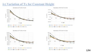
1. iv) Variation of Tx for Constant Height
1/64
-600.00
-400.00
-200.00
0.00
200.00
400.00
600.00
800.00
1000.00
1200.00
0.0 20.0 40.0 60.0 80.0 100.0
Tx
in
kN/m
% of 𝛗k
Variation of Tx for h=2m
B=6m B=8m B=10m B=12m B=14m
B=16m B=18m B=20m B=22m
-1000.00
-500.00
0.00
500.00
1000.00
1500.00
0.0 20.0 40.0 60.0 80.0 100.0
Tx
in
kN/m
% of 𝛗k
Variation of Tx for h=2.5m
B=6m B=8m B=10m B=12m B=14m
B=16m B=18m B=20m B=22m
-600.00
-400.00
-200.00
0.00
200.00
400.00
600.00
800.00
1000.00
1200.00
0.0 20.0 40.0 60.0 80.0 100.0
Tx
in
kN/m
% of 𝛗k
Variation of Tx for h=3m
B=6m B=8m B=10m B=12m B=14m
B=16m B=18m B=20m B=22m
-600
-400
-200
0
200
400
600
800
1000
0.0 20.0 40.0 60.0 80.0 100.0
Tx
in
kN/m
% of 𝛗k
Variation of Tx for h=3.5m
B=6m B=8m B=10m B=12m B=14m
B=16m B=18m B=20m B=22m
2. v) Variation of Tx for Constant Breadth
2/64
-600.00
-400.00
-200.00
0.00
200.00
400.00
600.00
800.00
1000.00
0.0 20.0 40.0 60.0 80.0 100.0
Tx
in
kN/m
% of 𝛗k
Variation of Tx for B=6m
h=2m h=2.5m h=3m
-600.00
-400.00
-200.00
0.00
200.00
400.00
600.00
800.00
1000.00
0.0 20.0 40.0 60.0 80.0 100.0
Tx
in
kN/m
% of 𝛗k
Variation of Tx for B=8m
h=2m h=2.5m h=3m h=3.5m
-600.00
-400.00
-200.00
0.00
200.00
400.00
600.00
800.00
1000.00
0.0 20.0 40.0 60.0 80.0 100.0
Tx
in
kN/m
% of 𝛗k
Variation of Tx for B=10m
h=2m h=2.5m h=3m h=3.5m
-600.00
-400.00
-200.00
0.00
200.00
400.00
600.00
800.00
1000.00
0.0 20.0 40.0 60.0 80.0 100.0
Tx
in
kN/m
% of 𝛗k
Variation of Tx for B=12m
h=2m h=2.5m h=3m h=3.5m
-600.00
-400.00
-200.00
0.00
200.00
400.00
600.00
800.00
1000.00
1200.00
0.0 20.0 40.0 60.0 80.0 100.0
Tx
in
kN/m
% of 𝛗k
Variation of Tx for B=14m
h=2m h=2.5m h=3m h=3.5m
-600.00
-400.00
-200.00
0.00
200.00
400.00
600.00
800.00
1000.00
1200.00
0.0 20.0 40.0 60.0 80.0 100.0
Tx
in
kN/m
% of 𝛗k
Variation of Tx for B=16m
h=2m h=2.5m h=3m h=3.5m
3. v) Variation of Tx for Constant Breadth
3/64
-600.00
-400.00
-200.00
0.00
200.00
400.00
600.00
800.00
1000.00
1200.00
0.0 20.0 40.0 60.0 80.0 100.0
Tx
in
kN/m
% of 𝛗k
Variation of Tx for B=18m
h=2m h=2.5m h=3m h=3.5m
-600.00
-400.00
-200.00
0.00
200.00
400.00
600.00
800.00
1000.00
1200.00
0.0 20.0 40.0 60.0 80.0 100.0
Tx
in
kN/m
% of 𝛗k
Variation of Tx for B=20m
h=2m h=2.5m h=3m h=3.5m
-1000.00
-500.00
0.00
500.00
1000.00
1500.00
0.0 20.0 40.0 60.0 80.0 100.0
Tx
in
kN/m
% of 𝛗k
Variation of Tx for B=22m
h=2m h=2.5m h=3m h=3.5m
4. vi) Influence of Tx (Observations)
4/64
For constant values of h, Values of Tx decreases at the edges but it becomes constant at the crown
when B increases.
For constant values of h, values of Tx change its sign moving from edge towards the crown.
For constant value of h, there is no significant difference in the value of Tx at crown on increasing the
value of B.
Decreasing both B and h, value of Tx increases at edge.
At 40% to 45% of 𝛗k, Tx always changes its sign moving from edge towards the crown for both
constant values of h and B.
5. 10) Conclusions
5/64
From the case studies of the long barrel thin cylindrical shells and the parametric study, following are the key points observed and
conclusions made.
● In interior panels of multiple barrel cylindrical shells of higher breadths, transverse moment has similar value at every
section of the barrel irrespective of height. So similar reinforcements can be provided in the design of those barrels.
● Huge amount of longitudinal compressive force exists in the interior panels of multiple barrel cylindrical shell which becomes
tensile with almost half its magnitude moving from edge towards the crown. The force changes its sign at 40%-45% of the
percentage of the 𝛗k. So special consideration must be done in design of that section.
● With the increase in complexity of simply supported shell ie by making it continuous or multiple barrel, FEM solution deviates
at the intersecting lines of the models and is observed to have a high percentage of error there. So, an analytical based program
considering the continuity of equations of curves in complex structures leads to the nearest results.
● In FEM analysis, when the structure is provided with intermediate support conditions, the accuracy of the analysis
increases.
● FEM doesn’t account for curvature in shell analysis as FEM solution is seen deviating at the crown of cylindrical shells.
Hence, quality of meshing also determines the accuracy of FEM solution.
6. 11) Limitation of the Study
6/64
The classical shell theory develops the higher order differential equations to solve the problems of arbitrary geometries.
Those arbitrary geometries can only be solved approximated by using the finite element method or the numerical evaluation
of infinite series. So, analytical solutions of complex geometries exist only for limited number complexities. But, those
solutions offer vital function in the evaluation of FEM or modern FEM based software. However, to analyze shells with
arbitrary geometry that interact with various supports and edge beams for static and dynamic solution of shells, the practical
approach is only provided by FEM.
7. 12) Further Research Topic for the Researchers
7/64
From this paper, it is seen that with the increase in complexity of the cylindrical shell structure, FEM based solution highly
deviates at the intersecting line. The stiffness matrix used by the FEM solution has been derived in Chapter 2 of this paper.
So, researchers can develop FEM based program and observe why FEM solution lacks proper solution at the intersecting
lines.
8. 13) References:
1. ASCE MANUAL NO-31: Design of cylindrical concrete shell roofs, prepared by the Committee on Masonry and
Reinforced Concrete of the Structural Division, through its Subcommittee on Thin Shell Design. American Society
of Civil Engineers. New York, N.Y.: The Society, 1952
2. IS: 2210–1988, CRITERIA FOR DESIGN OF REINFORCED CONCRETE SHELL STRUCTURES AND
FOLDED PLATES (First Revision)
3. Daryl L. Logan (2015) “First Course in the Finite Element Method” University of Wisconsin–Platteville
4. “Parametric study on the structural forces and the moments of cylindrical shell roof using ANSYS” by Ashique
Jose , Ramadass S and Jayasree Ramanujan
5. Kaushalkumar M. Kansara (2004) “Development of Membrane, Plate and Flat Shell Elements in Java”
6. Nawfal Hasaine (www.mathworks.com) “Satic Structural Analysis of Shell Roof Structure”
7. http://nptel.iitm.ac.in/
8/64