1. Vol-1 Issue-2 2015 IJARIIE-ISSN(O)-2395-4396
1181 www.ijariie.com 353
Study Of Microchannels With Fins For
Effective Cooling Of Electronic Equipment
With Help Of Cfd
1
Vishal S.Sanap, 2
Dr. S.V. Dingare,
1
Student, M.E. Heat Power , 2
Professor, Dept. of Mech. Engineering
1,2
MAEER'S MIT ,College Of Engineering, Kothrud, Pune
ABSTRACT
This paper includes Numerical study of different microchannel with internal fins to investigate fluid flow and
heat transfer characteristics. Three types of microchannels are studied –square channel with conventional and
cross fins and rectangular channel with conventional fins. Constant heat flux boundary conditions were
assumed on external walls of microchannel along with mass flow inlet and atm pressure outlet condition. Result
of average local nusselt no distribution along the channel length were obtained as function of the fin height
ratio. The analysis was carried out for different fin height and flow parameters in presence of a
hydrodynamically developed, thermally developing laminar flow. The existence of optimum fin height ratio for
each type of microchannel is found out in present study.
Keywords—; Microchannel; Electonic cooling; Heat flux; liquid cooling.
1. INTRODUCTION
In the natural system such as lungs and kidney in the human and other animals it has been observed that the
transport processes become more efficient at microscale level dimensions. The increase in the area/volume ratio
of passage and the change in the relative importance of different forces create new class of transport process that
can lead to significant size reductions in practical devices utilizing this process. Although this benefits are well
known as demonstrated by pioneering work of Tuckerman and Peace (1) significant research in this area started
only after their successful application in high heat flux electronics cooling and microfluidic devices. The
definition of microscale is somewhat flexible depending on dimension at which the transport characteristics are
affected. In general channel dimension of 10-200µm are considered microscale.For improving operation
reliability of electronic products efficient removal of internally generated heat is very important which also
affect design consideration of microelectronic components. As many modern devices are densely packed with
microelectronic circuit. Internal heat generated also increased and heat dissipation requirements have
exponentially increased. So traditional cooling technique like fan cooling has become insufficient and imposes
limits on product design. A significant amount of research has been made for developing some innovative
cooling technique that have potential to deliver high heat flux rates for microelectronic application. The concept
of microchannel can be best practical alternative for meeting the future cooling needs of advanced electronic
2. Vol-1 Issue-2 2015 IJARIIE-ISSN(O)-2395-4396
1181 www.ijariie.com 354
applications. The use of very large scale integrated (VLSI) electronic modern devices where internal heat
generation has dramatically increased microchannel heat sink with passive enhancement devices find
application in portable electronic equipment , miniature fuel cells etc and have become major focal point for
challenging research activities in the field of heat transfer.
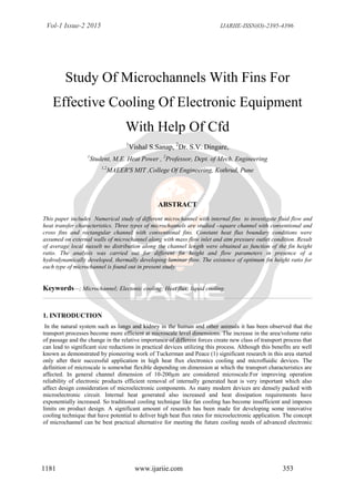
2. MODEL FORMULATION AND SOLUTION PROCEDURE :-
(b)
Fig.1.(a) Schematic diagram showing the cross section of square microchannel with conventional internal
fins.(b) Computational domain and the grid pattern
The square channel is 200 μm (W) x 200 μm (H) in crosssection, and 120 mm (L) in length and rectangular
channel is 400 μm (W) x 200 μm (H) in cross-section, and 120 mm (L) in length . The microchannel and all the
3. Vol-1 Issue-2 2015 IJARIIE-ISSN(O)-2395-4396
1181 www.ijariie.com 355
internal fins are considered to be made of aluminium. Channel wall thickness (tw) of 10 um and fin thickness
(tf) of 20μm are used in the study, and are kept constant. Fin height ratios H* from 0 (nofin) to 0.9 were
considered in the modeling
Fig.1(c) Schematic diagram showing the cross section of square microchannel with cross internal fins.
Fig.1.(d) Schematic diagram showing the cross section of rectangular microchannel with conventional internal
fins
The dashed lines shown in Fig. 1(a) are the boundaries of the computational domain, where symmetrical
boundary conditions are considered. The external walls of the channel are subjected to a uniform heat flux
thermal boundary condition. A uniform heat flux of 5×10⁵ W/m2 is applied at the four external walls of the
4. Vol-1 Issue-2 2015 IJARIIE-ISSN(O)-2395-4396
1181 www.ijariie.com 356
channel. Hydrodynamically fully developed laminar flow of water at an inlet temperature of 300 K is assumed
to enter the channel. The flow is assumed to be steady, and undergoes thermal boundary layer development from
the inlet of the channel. The microchannel is sufficiently long, such that both hydrodynamically and thermally
fully developed flow is obtained at the channel outlet. The following boundary conditions are specified: atm
pressure boundary condition at the channel and symmetrical boundary condition at the symmetrical wall. The
symmetrical boundary condition reduces the number of nodes required for the model, and thus reduces the
computational time and iteration for convergence. The symmetrical boundary condition assumes that no
diffusion flux transfer occurs across the symmetry plane, and that the normal gradients of all flow variables are
zero. The Reynolds number is suitably varied within the laminar region (1100—1330) with a constant mass flow
rate of 2.2×10⁻⁴ kg/s for square channel and 4.4×10⁻⁴ kg/s for rectangular channel for all fin height ratios.
Assuming steady, laminar and incompressible flow conditions together with the specified boundary conditions,
the continuity, Navier-Stokes, and the energy equation were solved using the Finite volume based computational
fluid dynamics solver FLUENT 6.3. The following governing equations were used in the mathematical
modelling.
Fig.1(b) shows the computational domain and the grid pattern. For the sake of completeness, the boundary
conditions corresponding to fig.1(b) are mathematically restated below
5. Vol-1 Issue-2 2015 IJARIIE-ISSN(O)-2395-4396
1181 www.ijariie.com 357
The SIMPLE algorithm was used to solve the pressure velocity coupling. The standard discretization scheme
was used in the modelling following the first order upwind of the momentum and energy discretization. The
convergence criterion that was used to ensure accuracy in the modelling is less than 10-6 for the scaled residues
of mass and momentum flux. The average local Nusselt number and surface heat transfer coefficients were
obtained from the numerical simulation once the convergence criterion was satisfied. The average local Nusselt
number and the convective heat transfer coefficient on the inside walls of the channel are defined using the
following equations.
In above Eqs Tw is the local average wall temperature, Tb is the local bulk fluid temperature. 2.1 Grid
Independence : Grid independence test was conducted on the square unfinned channel to ensure that the
obtained result does not depend on the meshing scheme followed. This involved meshing the same geometry of
a square unfinned channel using three different grid sizes and comparing their results. Uniform hexahedral cells
of 10×10×400 (coarse), 20×20×400 (medium) and 40×40×400 (fine) were considered for the grid independence
study. The local average Nusselts number at the exit for unfinned microchannel was obtained as 4.17, 4.05 and
4.03 respectively. Thus upon refinement from coarse to medium grid, an improvement of 2.87% was obtained
and upon further refinement from medium to fine mesh only 0.49% improvement was obtained. The variation of
average local Nusselts number with distance from the inlet of the channel obtained from the grid independence
test for finless channels is shown in the fig 2. It can be seen from the graph that the variation of the results with
alteration the grid is very negligible. Thus, based on the results obtained from the grid independence study, the
medium grid size was chosen for further work involving numerical computations, taking advantage of the
accuracy of the refinement process, data storage, and computational time.
6. Vol-1 Issue-2 2015 IJARIIE-ISSN(O)-2395-4396
1181 www.ijariie.com 358
3. RESULTS AND DISCUSSION :
3.1. Conventional Unfinned Channel :
The fully developed average local Nusselt numbers for the present study was obtained as 4.05 and from the
literature, this value was found to be 3.676. The computational error in the Nusselts number was thus around
9%, which although not a large deviation, may be justified by the convergence criteria adopted. The present
study adopts a convergence criteria of 10-6 in view of the computational time constraints, whereas from those
adopted by the authors may be still lower.
3.2. Conventional Finned Square Channel : With the channel wall thickness and fin thickness held constant, the
fin height ratio was suitably varied. A constant mass flow rate of 2.2 × 10⁻⁴ kg/s was given as the inlet for each
case, while varying the fin height ratio. The external dimensions of the channel were also held a constant for all
cases. Fig 3 shows the average local Nusselt number as a function of distance from the inlet of the channel for
some typical cases considered. A larger average local Nusselt number could be seen at the entrance of the
channel due to the development of the thermal boundary layer with the entrance section as the leading edge of
the channel. Nusselt number converges asymptotically to a fully developed value at the outlet of the channel. At
any particular channel location from the inlet, it can be seen that as the fin height increases, the average local
Nusselt number values also increase. However, for a fin height ratio H* of 0.80, the average local Nusselt
numbers are lower, when compared to the case of a fin height ratio H* of 0.60. This clearly shows that there is
an optimum value that lies between fin height ratios H* from 0.60 to 0.80. Curve fitting technique and
interpolation were used to determine the optimum value of the fin height ratio, H*. The optimum value fin
height ratio H* is found to be 0.67.
7. Vol-1 Issue-2 2015 IJARIIE-ISSN(O)-2395-4396
1181 www.ijariie.com 359
As stated earlier, the fully developed Nusselt number value for an unfinned square microchannel obtained from
the present numerical simulation is found to be 4.05. The Nusselt number for a microchannel having internal
fins and fully developed flow for an optimum fin height ratio H* of 0.675 is found to be 9.15. This clearly
shows that the Nusselt number is about 2.26 times higher for an internally finned microchannel when compared
to an unfinned microchannel, thereby reinforcing the advantage of this passive heat transfer enhancement
technique. Fig 4 shows the variation of average local Nusselt number as a function of the fin height ratio H* for
several cases considered in this study. This graph obviously shows the peak Nusselt number at H*=0.67. For a
given fluid, the thermal development length is a function of the hydraulic diameter, Prandtl number and the
Reynolds number. For the same mass flow rate, in an internally finned channel, the flow reaches fully developed
conditions at a shorter distance from the inlet than an unfinned channel. This is due to the fact that for the same
mass flow rate in both the channels, the finned channel provides a smaller hydraulic diameter. An important
factor that goes into consideration for flow through a microchannel is the pressure drop. Increase in the pressure
drop increases the pumping power needed for the micropump. Fig 5 the plot of pressure drop and the average
local Nusselt number in the microchannel, as a function of the fin height ratio H*. As can be seen from graph,
from the pressure drop point of view, there is no benefit in increasing the fin height ratio beyond the optimum
value.
8. Vol-1 Issue-2 2015 IJARIIE-ISSN(O)-2395-4396
1181 www.ijariie.com 360
3.3 Cross Finned Square Channel :
Cross finned microchannels were introduced with the objective of improving the Nusselt number, owing to the
fact that the wetted perimeter is obviously higher than that of conventional fins. The fins are erected from the
corners and extend diagonally as was shown earlier in fig 1(c). As in the case of conventional finned channels,
channel wall thickness and fin thickness were held constant and the fin height ratio was varied. Fig 3. shows the
9. Vol-1 Issue-2 2015 IJARIIE-ISSN(O)-2395-4396
1181 www.ijariie.com 361
average local Nusselt number as a function of distance from the inlet of the channel. A similar explanation can
be given for a larger value of average local Nusselt number at the entrance section and the asymptotic
convergence of the Nusselt number to a fully developed value, as in the case of conventional finned channels. It
can be seen that as the fin height increases, at any particular channel location from the inlet the average local
Nusselt number values also increase. However, unlike conventional finned channels, the optimum value of fin
height ratio H* is found to be 0.80, corresponding to 0.67 of the latter. Although a higher Nusselt number was
expected for the cross finned channels, the optimum value is lower than that of conventional fins.
Corresponding to the optimum Nusselt number of 9.15 at a fin height ratio of 0.67, the optimum value obtained
here was 8.11 at a fin height ratio of 0.80. The presence of more acute corners than that of the latter and the
corresponding drop in velocities at the corners may be interpreted as the reason for this unexpected lower result.
Fig 6 shows the variation of average local Nusselt number as a function of the fin height ratio H* for several
cases considered in this study. It can be seen that the value of average local Nusselt number first drops with
increase in fin height, due to the stagnant effects of the fluid in the corners. But still higher fin heights tend to
increase this as surface area of heat transfer increases. Explanations for thermal development length and
pressure drop can be adopted from that of conventional channels.
3.4 Rectangular Channels With Aspect Ratio 2 :
The study was extended to rectangular channels, where the horizontal and vertical fin height ratios H1* and
H2* are varied independently. Here too the external dimensions, fin and channel thickness were kept constant
and the fin height ratios were varied individually, keeping the mass flow rate same at 4.4×10⁻⁴ kg/s. The aim of
this study was to check whether the optimum fin height, if present could be found out by varying the horizontal
and vertical fin height ratios equally or independently. was varied from 0.3 to 0.9. A total of 56 cases were
10. Vol-1 Issue-2 2015 IJARIIE-ISSN(O)-2395-4396
1181 www.ijariie.com 362
solved excluding that of finless rectangular channel. Fig 7 shows the average local Nusselt number as a function
of distance from the inlet of the channel.
The fully developed average local Nusselt number for unfinned square microchannel was found to be 4.88.
From all the values obtained, the maximum Nusselt number was found to be 10.08 for the case in which
H1*=0.60 and H2*=0.80. It is thus observed that the optimum value cannot be reached by varying the horizontal
and vertical fin height ratios equally. Moreover it is inferred that the effect of varying the fin height ratio of
longer side (here H2*) is better than that of varying the shorter one, which is evident from the higher slope of
the surface near H2* kept constant at 0.9 and H1* varied suitably The Nusselt number thus got improved by
11. Vol-1 Issue-2 2015 IJARIIE-ISSN(O)-2395-4396
1181 www.ijariie.com 363
2.07 times from the finless value by the addition of fins in the optimum way. A table and graph showing the
average local Nusselt number at exit for all the cases solved are also given. It should be noted that all this
improvement in the Nusselt number was obtained at the expense of pressure drop. So it may be stated that the
primary constrain for choosing the fin height of microchannels is the pumping power of the micropump
employed.
3.5. Contours Of Velocity :
The contours of velocity at the exit section for different fin heights are shown in Fig 9. It is interesting to
observe the migratory patterns of the velocity. In an unfinned channel, the region of maximum velocity fluid is
always at the centre of the channel. When internal fins are added to the channel, the region of maximum velocity
is shifted. In the case of four fins, as the fin height increases, the region of maximum velocity moves
progressively, to four separate zones formed due to the presence of the fins. The existence of an optimum fin
height is also very clear from figure. The figures show the development of flow pattern within the microchannel
as the fin height increases. As can be seen from Fig 9, there is a significant change in the flow pattern for fin
height ratios H* =0.4, 0.6,0.8 and 0. 9. For the cases considered in this study, the best flow situation is found to
occur for H* = 0.8. For this case, it can also be seen that there is significant improvement in the corner flow,
which helps to enhance the heat transfer in the microchannel. However for fin height above the optimum eight
ratio H* = 0.9, the flow pattern is not favorable for maximum heat transfer due to the stagnation of the fluid t the
centre of the channel.
12. Vol-1 Issue-2 2015 IJARIIE-ISSN(O)-2395-4396
1181 www.ijariie.com 364
For a deep insight into the phenomenon of the increase in heat transfer coefficient due to the presence of fins,
the fluid velocity distribution is plotted along the diagonal extending from the center of the microchannel to one
of the corners in the exit plane for the case of conventional square finned channels. This is done for H* varying
from 0 to 0.90. For finless channel, the peak velocity occurs at the center of the channel. With the increase in
H*, the velocity at center decreases and new peaks occur at the side quadrants of the channel. For the case of the
channel having the optimum fin height ratio, the peak fluid velocity is found to occur at the centre region of the
channel and at the side quadrants of the channel. A higher fluid velocity near the fins and at the heated section
increases the convective heat transfer in the channel.
Any further increase of the fin height ratio beyond the optimum value alters the flow across the centre of the
channel, and the fin tip would not be effective in contributing to the convective heat transfer process that occurs
within the channel. Similar interpretation can be done in case of cross finned channels also. Instead of diagonal
lines, straight lines are drawn at the exit section. Velocity variation is plotted along its length. It is maximum at
the center of channel and comes down to 0 at the walls. With the introduction of fins diagonally, redistribution
takes place and new peaks are formed. The optimum is the case when all the peaks of fluid velocity are of
13. Vol-1 Issue-2 2015 IJARIIE-ISSN(O)-2395-4396
1181 www.ijariie.com 365
similar magnitude, which happens for H*=0.8. Diagonal line at the exit is drawn again for rectangular channels
where the velocity is plotted and peaks of similar magnitude corresponds to maximum Nusselt number at
H1*=0.60;H2*=0.80 3.6. Comparison With Published Results: In order to validate the modelling scheme, the
unfinned channel results of Ramesh and Chandratilleke [13] were compared with a case of an unfinned channel
modelled in the present study. The fully developed average local Nusselt numbers for both the cases were
compared. For the present study, this value was obtained as 4.05 and from the literature, this value was found to
be 3.676. The computational error in the Nusselts number was thus around 9%, which although not a large
deviation, may be justified by the convergence criteria adopted. The present study adopts a convergence criteria
of 10-6 in view of the computational time constraints, whereas from those adopted by the authors may be still
lower. Moreover, the thermo-physical properties were assumed to be temperature dependent. The scheme
adopted by the authors is unavailable.
4.CONCLUSION :
Based on this numerical study, it was concluded that internal fins in a microchannel have the potential to
provide heat transfer augmentation. The work done by Ramesh and Chandratilleke were validated. For a given
microchannel, there is an optimum fin height that provides the best possible heat transfer and pressure drop
characteristics. The optimum fin height ratio H* for a square microchannel found in this study is 0.67. The
following beneficial features are also realized in a microchannel with internal longitudinal fins as compared to
an unfinned microchannel: shorter length required for the development of the thermal boundary layer, better
flow mixing, steeper velocity gradient at the heated surface, increase in the surface area for heat transfer, and
increase in surface heat transfer coefficient and Nusselt number. Similar studies were conducted on cross finned
channels, and the optimum height ratio was found to be 0.80. The cross fin microchannels which when
compared with the conventional finned microchannels failed to show any improvement of the optimum Nusselt
number as expected. Moreover, the additional pressure drop and manufacturing constrains makes the
conventional channels more efficient. From study of all the cases of rectangular channels it was understood that
the optimum value might not be reached by varying the fin height ratios simultaneously equally. Improvement
of fully developed Nusselt number by almost 2.07 times was obtained by adopting a fin height ratio of
H1*=0.60 by H2*=0.8.
5. FUTURE SCOPE OF WORK :
Future scope may include extending the study to higher aspect ratio microchannels, and developing a general
correlation for optimum fin heights with aspect ratio of the channel considered.
REFERANCES :
[1] D.B. Tuckerman, R.F.W. Pease, ―High -performance heat sinking for VLS‖I, IEEE Electron. Dev. Lett.‖,
EDL 2 (5) (1981) 126 –129.
[2] P.S. Lee, S.V. Garimella, D. Liu, ―Investigation of heat transfer in rectangular microchannels‖, Int. J. Heat
Mass Transfer 48 (2005) 1688 –1704.
14. Vol-1 Issue-2 2015 IJARIIE-ISSN(O)-2395-4396
1181 www.ijariie.com 366
[3] W. Qu, I. Mudawar, ―Experimental and numerical study of pressure drop and heat transfer in a single -
phase microchannel heat sink‖, Int. J. Heat Mass Transfer 45 (2002) 2549 –2565.
[4] P.S. Lee, S.V. Garimella, ―Thermally developing flow and heat transfer in rectangular microchannels‖‖ Int.
J. Heat Mass Transfer 49 (17) (2006) 3060 –3067.
[5] A.G. Fedorov, R. Viskanta, ―Three dimensional conjugate heat transfer in the microchannel heat sink for
electronic packaging‖‖ Int. J. Heat Mass Transfer 43 (3) (2000) 399 –415.
[6] I. Alam, P.S. Ghoshdastidar, ―A study of heat transfer effectiveness of circular tubes with internal
longitudinal fins having tapered lateral profiles,‖Int. J. Heat Mass Transfer 45 (6) (2002) 1371–1376.
[7] Z.F. Dong, M.A. Ebadian, ―A numerical analysis of thermally developing flow in elliptical duct with
internal fins‖, Int. J. Heat Fluid Flow 12 (2) (1991) 166 –172.
[8] M.E. Steinke, S.G. Kandlikar, ―Single phase liquid friction factors in microchannels‖, Int. J. Therm. Sci. 45
(11) (2006) 1073 –1083.
[9] Ramesh and Chandratilleke, ‖ Laminar convective heat transfer in a microchannel with internal
longitudinal fins‖, International Journal of Heat and Mass Transfer 49 (2006) 3060 -3067.