1) The document describes a model for a wireless communication channel with multiple transmit and receive antennas, known as a MIMO channel. It accounts for multipath propagation through multiple propagation paths.
2) The capacity of the MIMO channel is analyzed. It is shown that multipath can substantially improve capacity over SISO, SIMO, and MISO channels if the number of multipath components exceeds a certain value. In this case, the capacity slope can be proportional to the number of antennas.
3) Two coding structures, STVC and DMMT, are proposed to achieve the MIMO channel capacity. STVC has very high complexity while DMMT has reduced complexity but can still achieve full channel capacity asymptot
![IEEE TRANSACTIONS ON COMMUNICATIONS, VOL. 46, NO. 3, MARCH 1998 357
Spatio-Temporal Coding for
Wireless Communication
Gregory G. Raleigh, Member, IEEE, and John M. Cioffi, Fellow, IEEE
Abstract—Multipath signal propagation has long been viewed linear MMSE vector transmission and reception filters for
as an impairment to reliable communication in wireless channels. channels with no excess bandwidth. More recent work
This paper shows that the presence of multipath greatly improves on MIMO equalizers includes the linear equalizer with excess
achievable data rate if the appropriate communication structure
is employed. A compact model is developed for the multiple-input bandwidth and the decision feedback equalizer [5]–[7].
multiple-output (MIMO) dispersive spatially selective wireless Consider the problem of communication with linear mod-
communication channel. The multivariate information capacity ulation in a frequency-dispersive spatially selective wireless
is analyzed. For high signal-to-noise ratio (SNR) conditions, the channel composed of transmission antennas and
MIMO channel can exhibit a capacity slope in bits per decibel reception antennas with additive noise. What is the impact
of power increase that is proportional to the minimum of the
number multipath components, the number of input antennas, or of multipath on the information capacity of the discrete time
the number of output antennas. This desirable result is contrasted communication channel? How do various multiple antenna
with the lower capacity slope of the well-studied case with multi- structures influence channel capacity? Is it possible to con-
ple antennas at only one side of the radio link. A spatio-temporal struct multiple antenna coding systems that benefit from the
vector-coding (STVC) communication structure is suggested as inherent properties of severe multipath channels? This paper
a means for achieving MIMO channel capacity. The complexity
of STVC motivates a more practical reduced-complexity discrete is a first attempt to answer these questions for time-invariant
matrix multitone (DMMT) space–frequency coding approach. channels such as those that exist in certain wireless local loop
Both of these structures are shown to be asymptotically optimum. applications. Time-varying channels are treated in [8] and [9].
An adaptive-lattice trellis-coding technique is suggested as a A compact MIMO channel model is developed in Section
method for coding across the space and frequency dimensions II. We then explore the theoretical information capacity limits
that exist in the DMMT channel. Experimental examples that
support the theoretical results are presented. of the MIMO channel in Section III. We find that multipath
substantially improves capacity for the MIMO case. Specifi-
Index Terms—Adaptive arrays, adaptive coding, adaptive mod- cally, if the number of multipath components exceeds a certain
ulation, antenna arrays, broad-band communication, channel
coding, digital modulation, information rates, MIMO systems, value, then the channel capacity slope in bits per decibel of
multipath channels. power increase can be proportional to the number of antennas
located at both the input and output of the channel. This
I. INTRODUCTION highly desirable result is contrasted with the more conventional
case with multiple antennas on only one side of the channel.
T HE SYSTEMATIC study of reliable communication in
linear channels was initiated by the work of Shannon
in 1948 [1]. The information capacity of certain multiple-
A spatio-temporal vector coding (STVC) structure for burst
transmission is suggested as a theoretical means for achieving
capacity. The high complexity of the STVC structure motivates
input multiple-output (MIMO) channels with memory was a more practical reduced-complexity discrete matrix multitone
derived by Brandenburg and Wyner [2]. Recent work by (DMMT) space–frequency coding structure which is analyzed
Cheng and Verdu [3] derives the capacity region for more in Section IV. Both STVC and DMMT are shown to achieve
general multiaccess MIMO channels. The problem of joint the true channel capacity as the burst duration increases.
optimization of a multivariate transmitter–receiver pair to In Section V, an adaptive-lattice trellis-coding technique is
minimize the mean-square error criteria (MMSE) has gained suggested as a practical method for coding across space and
considerable attention. One of the earliest contributions to this frequency dimensions in the DMMT channel. Experimental
problem was made by Salz [4], who developed the optimum examples that support the theoretical results are then reported
in Section VI.
Paper approved by T. Aulin, the Editor for Coding and Communication The main contributions in this paper are the matrix channel
Theory of the IEEE Communications Society. Manuscript received April 9,
1996; revised September 27, 1996 and July 21, 1997. This work was supported model development, the connection between rank and multi-
by Watkins-Johnson Company and by Clarity Wireless, Inc. This paper was path shown in Lemma 1, the multipath capacity behavior of
presented in part at the 1996 Global Communications Conference, November various multiple antenna structures highlighted by Corollaries
1996.
G. G. Raleigh is with Clarity Wireless, Inc., Belmont, CA 94002 USA (e- 2 and 3, introduction of DMMT as a realizable means to
mail: raleigh@clarity-wireless.com). achieve a multiplicative reliable rate advantage in dispersive
J. M. Cioffi is with the Department of Electrical Engineering, Stanford MIMO channels, and the asymptotic optimality proof for
University, Stanford, CA 94305-4055 USA, and with Amati Communications
Corporation, San Jose, CA 95124 USA. DMMT capacity Theorem 2. The results presented in this
Publisher Item Identifier S 0090-6778(98)02123-0. paper are based on the work previously reported in [10]–[12].
0090–6778/98$10.00 © 1998 IEEE](https://image.slidesharecdn.com/10-1-1-21-5598-090722003957-phpapp01/85/10-1-1-21-5598-1-320.jpg)
![IEEE TRANSACTIONS ON COMMUNICATIONS, VOL. 46, NO. 3, MARCH 1998 357
Spatio-Temporal Coding for
Wireless Communication
Gregory G. Raleigh, Member, IEEE, and John M. Cioffi, Fellow, IEEE
Abstract—Multipath signal propagation has long been viewed linear MMSE vector transmission and reception filters for
as an impairment to reliable communication in wireless channels. channels with no excess bandwidth. More recent work
This paper shows that the presence of multipath greatly improves on MIMO equalizers includes the linear equalizer with excess
achievable data rate if the appropriate communication structure
is employed. A compact model is developed for the multiple-input bandwidth and the decision feedback equalizer [5]–[7].
multiple-output (MIMO) dispersive spatially selective wireless Consider the problem of communication with linear mod-
communication channel. The multivariate information capacity ulation in a frequency-dispersive spatially selective wireless
is analyzed. For high signal-to-noise ratio (SNR) conditions, the channel composed of transmission antennas and
MIMO channel can exhibit a capacity slope in bits per decibel reception antennas with additive noise. What is the impact
of power increase that is proportional to the minimum of the
number multipath components, the number of input antennas, or of multipath on the information capacity of the discrete time
the number of output antennas. This desirable result is contrasted communication channel? How do various multiple antenna
with the lower capacity slope of the well-studied case with multi- structures influence channel capacity? Is it possible to con-
ple antennas at only one side of the radio link. A spatio-temporal struct multiple antenna coding systems that benefit from the
vector-coding (STVC) communication structure is suggested as inherent properties of severe multipath channels? This paper
a means for achieving MIMO channel capacity. The complexity
of STVC motivates a more practical reduced-complexity discrete is a first attempt to answer these questions for time-invariant
matrix multitone (DMMT) space–frequency coding approach. channels such as those that exist in certain wireless local loop
Both of these structures are shown to be asymptotically optimum. applications. Time-varying channels are treated in [8] and [9].
An adaptive-lattice trellis-coding technique is suggested as a A compact MIMO channel model is developed in Section
method for coding across the space and frequency dimensions II. We then explore the theoretical information capacity limits
that exist in the DMMT channel. Experimental examples that
support the theoretical results are presented. of the MIMO channel in Section III. We find that multipath
substantially improves capacity for the MIMO case. Specifi-
Index Terms—Adaptive arrays, adaptive coding, adaptive mod- cally, if the number of multipath components exceeds a certain
ulation, antenna arrays, broad-band communication, channel
coding, digital modulation, information rates, MIMO systems, value, then the channel capacity slope in bits per decibel of
multipath channels. power increase can be proportional to the number of antennas
located at both the input and output of the channel. This
I. INTRODUCTION highly desirable result is contrasted with the more conventional
case with multiple antennas on only one side of the channel.
T HE SYSTEMATIC study of reliable communication in
linear channels was initiated by the work of Shannon
in 1948 [1]. The information capacity of certain multiple-
A spatio-temporal vector coding (STVC) structure for burst
transmission is suggested as a theoretical means for achieving
capacity. The high complexity of the STVC structure motivates
input multiple-output (MIMO) channels with memory was a more practical reduced-complexity discrete matrix multitone
derived by Brandenburg and Wyner [2]. Recent work by (DMMT) space–frequency coding structure which is analyzed
Cheng and Verdu [3] derives the capacity region for more in Section IV. Both STVC and DMMT are shown to achieve
general multiaccess MIMO channels. The problem of joint the true channel capacity as the burst duration increases.
optimization of a multivariate transmitter–receiver pair to In Section V, an adaptive-lattice trellis-coding technique is
minimize the mean-square error criteria (MMSE) has gained suggested as a practical method for coding across space and
considerable attention. One of the earliest contributions to this frequency dimensions in the DMMT channel. Experimental
problem was made by Salz [4], who developed the optimum examples that support the theoretical results are then reported
in Section VI.
Paper approved by T. Aulin, the Editor for Coding and Communication The main contributions in this paper are the matrix channel
Theory of the IEEE Communications Society. Manuscript received April 9,
1996; revised September 27, 1996 and July 21, 1997. This work was supported model development, the connection between rank and multi-
by Watkins-Johnson Company and by Clarity Wireless, Inc. This paper was path shown in Lemma 1, the multipath capacity behavior of
presented in part at the 1996 Global Communications Conference, November various multiple antenna structures highlighted by Corollaries
1996.
G. G. Raleigh is with Clarity Wireless, Inc., Belmont, CA 94002 USA (e- 2 and 3, introduction of DMMT as a realizable means to
mail: raleigh@clarity-wireless.com). achieve a multiplicative reliable rate advantage in dispersive
J. M. Cioffi is with the Department of Electrical Engineering, Stanford MIMO channels, and the asymptotic optimality proof for
University, Stanford, CA 94305-4055 USA, and with Amati Communications
Corporation, San Jose, CA 95124 USA. DMMT capacity Theorem 2. The results presented in this
Publisher Item Identifier S 0090-6778(98)02123-0. paper are based on the work previously reported in [10]–[12].
0090–6778/98$10.00 © 1998 IEEE](https://image.slidesharecdn.com/10-1-1-21-5598-090722003957-phpapp01/75/10-1-1-21-5598-1-2048.jpg)
![358 IEEE TRANSACTIONS ON COMMUNICATIONS, VOL. 46, NO. 3, MARCH 1998
Synchronous complex baseband sampling with symbol pe-
riod is assumed for the receiver. We define and
to be the maximum lag and length over all for the sampled
pulse function sequences To simplify notation,
it is assumed that , and the discrete-time notation
is adopted.
When a block of data symbols are transmitted,
nonzero output samples result, beginning at time sample
and ending with sample The composite
channel output can now be written as a column vector with all
time samples for a given receive antenna appearing in order
Fig. 1. Illustration of the physical wireless channel. so that
, with an identical stacking for the output
II. MIMO CHANNEL MODEL noise samples The input symbol vector is written
Wireless communication channels are often characterized by The
severe multipath [13], [14]. The transmitted signal propagates spatio-temporal channel may then be expressed as a vector
along multiple paths created by reflection and scattering equation
from physical objects in the terrain as illustrated in Fig. 1.
(1)
We derive a far field1 signal model for linearly modulated
digital communication for a system with transmitting where the MIMO channel matrix is composed of
antennas and receiving antennas. In all that follows, single-input single-output (SISO) subblocks
complex valued baseband signal models are used. The implicit
assumption is that a radio frequency carrier upconverts the
baseband communication signal which is transmitted over the .
. .. .
.
. . .
air and then coherently demodulated back to baseband at the
receiver.
Considering the propagation geometry for the th propaga- with each subblock possessing the well-known Toeplitz form.
tion path, the th transmit antenna gain response2 due to the To clearly illustrate the effect of multipath, the channel can be
angle of departure is and the th receive antenna gain written as the sum over multipath components3
response due to angle of arrival is The th
propagation path is further characterized by a complex path
.
.
amplitude and a path propagation delay This propagation .
geometry is depicted in Fig. 2.
In the context of a digital signaling scheme, the transmitted (2)
baseband signal for the th transmitter element is
where the Toeplitz pulse shaping matrix is
.
. .. .. .. .. .
.
where is the (complex) symbol sequence, is the . . . . . .
pulse shaping function impulse response, and is the symbol
period. The pulse shaping function is typically the convolution
of two separate filters, one at the transmitter and one at the .
. .. .. .. .. .
. (3)
. . . . . .
receiver. The optimum receiver filter is a matched filter. In
practice, the pulse shape is windowed, resulting in a finite
.
. .. .. .. .. .
.
duration impulse response. The received signal for the th . . . . . .
antenna is then
This channel description is illustrated in Fig. 3.
Lemma 1: The number of finite amplitude parallel spatio-
temporal channel dimensions that can be created to commu-
nicate over the far field channel described by (1) is bounded
by
where is the additive receiver noise.
(4)
1 Here, the far field assumption implies that dominant reflectors are suffi-
ciently far from the arrays so that the angles of departure, angles of arrival, 3 In (2), the inherent assumptions are that each propagation path ampli-
and time delays are constant over the extent of the array aperture. tude](https://image.slidesharecdn.com/10-1-1-21-5598-090722003957-phpapp01/85/10-1-1-21-5598-2-320.jpg)
![360 IEEE TRANSACTIONS ON COMMUNICATIONS, VOL. 46, NO. 3, MARCH 1998
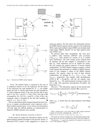
Proof: Given the matrix description we have adopted for Therefore, we can write
the spatio-temporal channel, the capacity proof is a simple
extension of the well-known capacity result for SISO channels
with memory [15].
Theorem 1 suggests an extension of the temporal vector
coding proposed by Kasturia et al. [16]. By choosing up to
spatio-temporal transmission sequences that are multiples
of the right singular vectors of , and receiving with up to
matched spatio-temporal filter vectors that are the left singular
vectors of , up to parallel subchannels are constructed.7
We coin this structure STVC. The STVC parallel channel is
written Repeating the above argument for the MISO channel concludes
the proof.
(7) The capacity slope of a communication channel is now
defined as the increase in capacity that results from multiplying
We now compare the asymptotic high SNR capacity behav- the SNR by a constant factor
ior of the wireless channel for various antenna configurations.
To simplify the discussion, we make the assumption8 that
so that the subchannel count bound (4) is well
approximated by Corollary 2: If multiple ports exist at both the input and
Definition: The full rank assumption is defined as the case output of the spatio-temporal communication channel ,
where equality is achieved in the subchannel count bound. then as the SNR increases, the capacity slope for the MIMO
Corollary 1: If multiple ports exist at only the input or channel approaches a constant times the capacity slope
only the output of the far-field spatio-temporal communication for any underlying SISO, SIMO, or MISO channel. Under the
channel , then as SNR increases, the capacity improvement full rank assumption, the asymptotic capacity slope multiplier
as compared to that of any underlying SISO channel is given by
approaches a constant. For SIMO channels the constant is (9)
given by
Thus, the capacity advantage of MIMO channel structures can
grow without bound as SNR increases provided that multipath
is present.
Proof: Following the first steps in the previous proof,
(8)
we can easily show
with a similar expression holding for MISO channels.
Proof: For the SIMO channel, define as the th
SISO subchannel entry in From Lemma 1, the rank
Thus, increasing the number of antennas at the output of
the channel does not increase parallel channel opportunities
for transmission. Choosing to transmit over is a subset
which leads directly to
of the transmission solutions available given ; therefore,
We define as the smallest singular
value amplitude in either or The water-filling solution
(6) uses all available subchannels when the transmit power In an identical manner, we find
exceeds
Repeating the above for MISO and SISO channels concludes
the proof.
Defining , the asymptotic high SNR water- Corollaries 1 and 2 are somewhat surprising. Multipath is an
filling power distribution for both channels is advantage in far-field MIMO channels. If there is no multipath
, then the high SNR capacity advantage of MIMO
communication structures is limited to a constant improvement
in bits as compared to SISO channels. If the multipath is severe
, the high SNR capacity can essentially
7 Note that the equivalent STVC receiver noise vector is still white due to
be multiplied by adding antennas to both sides of the radio link.
the orthogonality of the right singular vector matrix V H :
8 This assumption eliminates the mathematical inconvenience of dealing
This capacity improvement occurs with no penalty in average
with the ratio N + =N that would otherwise appear in Corollary 1, Corollary radiated power or frequency bandwidth because the number of
2, and the proofs when MT min(L; MR ): parallel channel dimensions is increased. In contrast, adding](https://image.slidesharecdn.com/10-1-1-21-5598-090722003957-phpapp01/85/10-1-1-21-5598-5-320.jpg)
![RALEIGH AND CIOFFI: SPATIO-TEMPORAL CODING FOR WIRELESS COMMUNICATION 361
multiple antennas to only one side of the radio link increases orthonormal singular vectors of the cyclic matrices , the
capacity by an additive term as compared to SISO channels new matrix is
regardless of the number of propagation paths. This is because
the number of parallel dimensions is not increased. This . .
. .. .
clearly provides theoretical motivation for optimal space–time . . .
communication structures that can be implemented in practice.
In the next section we develop a practical computationally
efficient approach to spatio-temporal coding that can achieve where is the diagonal matrix containing the eigenvalues
the multiplicative capacity advantage. of the cyclic channel submatrix Premultiplication
and post-multiplication by a permutation matrix , and post-
IV. DISCRETE MATRIX MULTITONE multiplication by a similar permutation matrix , yields the
block diagonal matrix
The main disadvantage with the space–time vector coding
solution is the associated computational complexity. The SVD
of an matrix must be computed. Com- .. (11)
.
plexity can be reduced by using a coding structure similar to
the discrete multitone (DMT) solution for the SISO channel
[17]–[19]. This new space–frequency coding structure results where
in a matrix of transmission and reception vector solutions for
each discrete Fourier transform (DFT) frequency index. We
therefore coin the method DMMT. . . .
For DMMT, data symbols are again transmitted from .
. .
. .
.
each antenna during each channel usage. However, a cyclic
prefix is added to the beginning of the data sequence so that the
is the space–frequency channel evaluated at DFT
last data symbols are transmitted from each antenna element
index
before transmitting the full block of symbols. By receiving
It is instructive to explore the nature of the
only time samples at the output of each antenna element,
space–frequency channel matrix Defining the
ignoring the first and last output samples, the DMMT
receive array response vector as the column vector
channel submatrices now appear as cyclic
and the transmit
structures. The new block cyclic channel matrix can again be
array response vector as ,
written as the matrix sum in (2) with the Toeplitz pulse shaping
it can be verified that
matrices replaced by the cyclic pulse shaping
matrices given in (10), shown at the bottom of the page.
Given the cyclic SISO channel blocks, we can diagonalize the (12)
new channel matrix with a three-step procedure. We first post-
multiply with the block diagonal inverse
where is the DFT of the sequence evalu-
discrete Fourier transform (IDFT) matrix
ated at DFT index . Thus, at each frequency index, the
DMMT channel is due to a weighted sum over rank-1
.. outer products of the frequency-invariant receive and trans-
.
mit array response vectors. The weighting is determined by
the frequency-invariant path fading values and the Fourier
where each diagonal block is the unitary by IDFT transform of the delayed pulse shaping function. This reveals
matrix The next step is to premultiply by a similar a highly structured nature for the space–frequency channel
by block diagonal DFT matrix where the spectrum.
diagonal submatrices are by DFT matrices. With the Given the SVD of , the
well-known result [20] that the DFT basis vectors form the diagonal DMMT channel matrix is finally obtained by
(10)](https://image.slidesharecdn.com/10-1-1-21-5598-090722003957-phpapp01/85/10-1-1-21-5598-6-320.jpg)
![362 IEEE TRANSACTIONS ON COMMUNICATIONS, VOL. 46, NO. 3, MARCH 1998
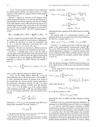
Fig. 4. DMMT system diagram.
postmultiplying by and premultiplying by continuous-frequency channel capacity given by
(14)
.. where is found from the space–frequency water-filling
.
solution
where is block diagonal, with each block containing (15)
the right singular matrices of the matrices, is
Proof: The DMMT noise sequence is still AWGN since
block diagonal containing the left singular matrices of the
matrices, and each of the diagonal submatrices contains the
DMMT spatial subchannel amplitudes where
The parallel channel DMMT equation is then
Given this, and the parallel independent channel structure of
(13) DMMT, it is clear that
where is the length input symbol vector, is
the length output symbol vector, and is the length
equivalent output noise vector. A block diagram archi- (16)
tecture that implements the DMMT space–frequency channel
decomposition is presented in Fig. 4. where
Assuming and , the
complexity of the vector coding solution computation has been
reduced to independent point IFFT’s, independent
point FFT’s, and independent by SVD’s resulting As , the noise sequence power spectrum remains flat
in a complexity of for DMMT. with power density It is well known that the DFT sequence
The signal processing complexity required at the transmit- converges to the continuous-frequency Fourier transform, so
ter and receiver to diagonalize all space–time subchannels ,9 which leads directly to
for each data block has been reduced from to
(17)
We now show that STVC and DMMT are both asymptot-
ically optimal. 9 Note that G (! )
l = (1=T ) 61 01 [Gct ((!=T )) 0 (2n=
n=
Theorem 2: In the limit as , the capacity of the T ))ej (!=T 0(2n=T )) ] is the folded frequency spectrum of the continuous-
STVC solution and the DMMT solution both converge to the time continuous-frequency Fourier transform Gct (! ) = F (g (t 0 l )):](https://image.slidesharecdn.com/10-1-1-21-5598-090722003957-phpapp01/85/10-1-1-21-5598-7-320.jpg)
![RALEIGH AND CIOFFI: SPATIO-TEMPORAL CODING FOR WIRELESS COMMUNICATION 363
and the channel matrix singular value becomes where is the spatial index and is the DFT frequency index.
Therefore, from the standard properties of Riemann The bit allocation per subchannel is then given by
integration, the summation in (16) converges to the desired
result for the DMMT structure. (21)
For the STVC case, the output noise is again AWGN. With
written as in (2), it is known [21], [22] that the singular It is not possible to achieve infinite bit resolution (granu-
value distribution for the Toeplitz matrix converges, as larity) with coset codes. Therefore, the solution in (21) must
, to the continuous-frequency Fourier transform of be modified. Several bit loading algorithms exist to resolve
Therefore, the STVC space–frequency channel also this problem. The granularity of possible bit allocations is
converges to (17). This concludes the proof. determined by the dimensionality of the coset code lattice
In the more general spatially continuous antenna case, the structure. A two-dimensional symbol [e.g., quadrature ampli-
summation over the discrete antenna index becomes an tude modulation (QAM)] in an eight-dimensional lattice has a
integration over continuous antenna volume index bit granularity of 0.25. In our MIMO channel communication
structures the orthogonal constellation dimensions are the
complex plane, space, and frequency (or time).
(18)
Referring now to [26], an effective coding method for
parallel channel systems is to “code across subchannels.” In
this technique the power and bit allocation for each subchannel
is computed as in (20) and (21), and each successive set of
(19)
input bits to the trellis encoder corresponds to a different trans-
mit subchannel. At each branch in the receiver’s maximum-
These equations suggest that an unexploited capacity mul-
likelihood sequence estimator (MLSE) the number of possible
tiplying advantage also exists for many distributed antenna
coset members and trellis branches are determined by the
structures commonly used in wireless communication. number of bits loaded onto the corresponding subchannel.
Using this technique, the maximum latency is approximately
V. SPATIO-TEMPORAL CODING [27]. The additive factor is associated with
the decoding delay to code across transmitted data blocks.
This section provides background on existing coding This factor can be eliminated using the so-called “tail biting”
schemes that can be used effectively to distribute information technique. If tail biting is used, there is a rate ratio penalty
over parallel space and frequency (or temporal) dimensions of approximately that is associated with always
that exist in STVC and DMMT channels. This discussion transmitting a known sequence at the end of the block so that
assumes estimation of the MIMO channel by transmitting the MLSE can complete the trellis decision sequence.
a series of training symbol sequences from each antenna Many of the other practical coding techniques developed
element and that the receiver and transmitter share the for parallel subchannel communication systems, not mentioned
information required to decompose the channel into here, can also be applied to the STVC and DMMT parallel
parallel subchannels. Estimating the DMMT channels can subchannel structures developed in the previous section.
be accomplished by using well-known SISO channel training
and estimation techniques for each of the channel subblocks
VI. EXPERIMENTAL EXAMPLES
The trellis codes first reported by Ungerboeck [23] led to the In this section the results of wireless DMMT simulation
general class of coset coding techniques reported by Forney experiments are reported. The first experiment compares the
[24]. The coset selection encoder is typically a convolutional capacity of an example wireless MIMO channel with the
code with constraint length and input to output coding ratio capacity of the underlying SIMO and SISO channel blocks.
The so-called “gap analysis” [25] provides an effective method The second experiment illustrates how DMMT can increase
for approximating the probability of error performance of reliable data transmission rates using practical coding schemes.
coset codes. In this technique, a particular coset code with an The third experiment illustrates the decrease in MIMO channel
associated lattice structure is characterized by first determining capacity that occurs if the number of multipath components is
the SNR required to achieve a theoretical capacity equal to less than the number of input and output antenna elements.
the desired data rate. The code gap is then the SNR multiplier
required to achieve the target probability of error at the desired Example 1:
data rate. In a parallel channel communication system this gap The STVC channel is described by (2). For the DMMT
can be used to determine the power and bit distributions that channel, the block Toeplitz matrix is replaced by the block
maximize data rate subject to a probability of error constraint. cyclic matrix All model parameters are generated randomly
With a coding gap of , the rate maximizing water-filling from probability distributions that approximate a realistic
solution for the DMMT channel becomes urban multipath channel. There are ten random multipath
components. The path time delays are drawn from a uniform
(20) distribution with a root-mean-square (rms) delay spread of 2
The transmission and reception angles and for](https://image.slidesharecdn.com/10-1-1-21-5598-090722003957-phpapp01/85/10-1-1-21-5598-8-320.jpg)
![364 IEEE TRANSACTIONS ON COMMUNICATIONS, VOL. 46, NO. 3, MARCH 1998
SIMO DMT channels are also computed. The transmitter
power penalty associated with transmitting the cyclic prefix11
is accounted for in the DMMT capacity results. Mean channel
capacity per symbol12 as a function of mean SNR13 per symbol
is plotted for each of the test cases.
The experimental results are in strong agreement with
Corollaries 1 and 2. For large SNR values, a 3-dB increase in
SNR results is a 4-bit increase in STVC channel capacity while
the SISO [Fig. 5(a)] and SIMO [Fig. 5(b)] DMT channels only
increase by 1 bit. This capacity slope multiplier corresponds
to the fourfold increase in spatial channel water-filling dimen-
sions associated with four channel inputs and four channel
outputs. At all SNR values the DMMT channel capacity is
significantly higher than the capacity of any of the SISO and
SIMO DMT channels. The STVC channel capacity is slightly
higher than the DMMT channel capacity. The difference is
essentially equal to the transmitted power penalty associated
(a) with the cyclic prefix.
Example 2:
In the second example the same experimental channels
described above are used again. The channels were evaluated
for achievable data rates using the coding gap dB)
for a well-known eight-dimensional trellis code applied across
space and frequency (time) subchannels. The results of the
second experiment are presented in Table I. The experimental
values for reliable data rate follow the same trends that were
observed in the capacity experiments. The DMMT channel bit
rate is much higher than all of the SIMO and SISO DMT
channels. The high SNR DMMT data rate slope is again 4
bits per 3 dB SNR increase while the SIMO DMT and SISO
DMT channels exhibit a slope of 1 bit per 3 dB increrase.
The experimental SISO multipath channels, with 300 kHz
channel spacing, would support data rates ranging from 1.7 to
6.0 b/symbol period, or 0.34 to 1.20 Mb/s, at a mean SNR
(b)
of 20 dB. This results in a data transmission efficiency from
Fig. 5. Channel capacity experimental results for L = 10: 1.1 to 4.0 b/s/Hz. When combined into a DMMT structure,
these same underlying SISO channels with the same frequency
each path are drawn from uniform distributions centered at bandwidth and transmitter power will support a data rate
0 with an rms angle spread of 25 The path amplitudes of 14.7 b/symbol period, or 2.94 Mb/s, for an efficiency of
are generated from a complex Gaussian distribution. The 9.8 b/s/Hz.
pulse shaping function is raised cosine with 5- symbol It may at first seem impractical to transmit an average of
period10 and rolloff factor 0.35. The pulse function duration 15 b/symbol due to the limits of practical constellation sizes.
is seven symbol periods and the lag Each antenna However, the DMMT data for each DFT bin is spread over
array contains four elements in a linear arrangement with an four orthogonal spatial subchannel dimensions. This reduces
interelement spacing of five carrier frequency wavelengths. the peak number of bits per tone that must be transmitted over
Each element has an omnidirectional radiation pattern. The any single subchannel. With a mean SNR of 20 dB, the peak
number of transmitted symbols per block is 64. The receiver experimental data load for any single DMMT space–frequency
noise for each antenna element is complex AWGN. subchannel is 7.2 b. The maximum data load for the best
The capacity of the 4 4 STVC channel is compared to the DMT SISO subchannel is 6.9 b and the maximum load for
capacity of the 4 4 DMMT channel in Fig. 5. To provide the best DMT SIMO subchannel is 8.1 b. Thus, even though
a reference for capacity improvement, the capacity values 11 The requirement to transmit the cyclic prefix results in an equivalent
for all 16 1 1 SISO DMT subchannels are computed. To DMMT transmission power of PT 1 N=(N + ):
provide another comparison, the capacity values for all 4 1 12 Mean capacity per symbol period is defined here as the total channel
capacity in bits for all parallel channels over the entire block, divided by N:
10 This pulse shape is consistent with certain existing personal communica- 13 Mean SNR per symbol is computed by averaging over all of the squared
tion services (PCS) wireless modulation schemes intended for wireless local channel singular values for all of the 16 SISO DMT channels and then
loop applications. 2
multiplying by the ratio PT =n (see footnote 4).](https://image.slidesharecdn.com/10-1-1-21-5598-090722003957-phpapp01/85/10-1-1-21-5598-9-320.jpg)