Python Notes for mca i year students osmania university.docx
1
1. 1. - TRANSFORMERS
One has generally only the tension of the sector, of which the most current values lie
between 110 and 240 V, but for the electronic instruments, the tensions necessary often
have a different value. The mains transformer precisely ensures the transformation of
the tension of the sector, while increasing or by decreasing its value in order to obtain
the supply voltages of the various circuits.
1. 1. - CONSTITUTION OF THE TRANSFORMER
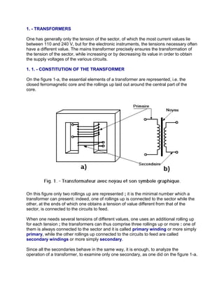
On the figure 1-a, the essential elements of a transformer are represented, i.e. the
closed ferromagnetic core and the rollings up laid out around the central part of the
core.
On this figure only two rollings up are represented ; it is the minimal number which a
transformer can present: indeed, one of rollings up is connected to the sector while the
other, at the ends of which one obtains a tension of value different from that of the
sector, is connected to the circuits to feed.
When one needs several tensions of different values, one uses an additional rolling up
for each tension ; the transformers can thus comprise three rollings up or more : one of
them is always connected to the sector and it is called primary winding or more simply
primary, while the other rollings up connected to the circuits to feed are called
secondary windings or more simply secondary.
Since all the secondaries behave in the same way, it is enough, to analyze the
operation of a transformer, to examine only one secondary, as one did on the figure 1-a.
2. On this figure, the primary education was drawn a little above it secondary to clearly
distinguish two rollings up which, actually, are superimposed: the primary education is
rolled up initially, then, the secondary.
On the figure 1-b, one drew the graphic symbol representing the transformer on the
electric diagrams: the same graphic symbol as that used in the preceding lessons to
represent rollings up of windings is used here for rollings up, while the core is
represented by a segment of right-hand side traced between the primary education and
the secondary. When there are several secondaries, one generally draws them all on
the same side of the segment, so that other side, it has only the primary education
there.
We will see now how a transformer functions, i.e. how its secondary can provide a
power of a value different from that which is applied to its primary education.
1. 2. - NO-LOAD TRANSFORMER
It is necessary us to examine initially how comprises transformer when the primary
education is connected to the sector and that the secondary is connected to no circuit
(one says that it is open), as on figure 2 ; under these conditions, one says that the
transformer functions in neutral, because its secondary does not provide any current.
The only current which circulates in the transformer is that which the primary education
connected to the sector absorbs; this current, when it traverses rolling up, magnetizes
the core, this is why it is called magnetizing current.
3. If one indicates by Np the number of whorls of the primary education and by Io the
magnetizing current, one obtains a f.m.m., given by the product Np x Io, which
produces flow in the core.
If we neglect, for the moment, the resistance of the driver which constitutes rolling up,
we see that the primary education behaves as a reel without resistance, provided with a
closed core and supplied with a AC current.
According to all that we saw in the preceding lessons, we can say that the primary
winding produces a f.e.m. self-induction (which we now indicate by Ep) equal to the
tension of the sector (that we call Vp). Actually, the Vp tension applied to the primary
education is slightly higher than the f.e.m. Ep because it must also compensate for the
voltage drop produced by the current magnetizing because of rolling up. However, as
this current is not very intense, the voltage drop is rather weak and one can thus neglect
it, by retaining consequently that, when the transformer functions in neutral, the Vp
tension applied to its primary education is equal to the f.e.m. Ep produced by this one
by self-induction.
On figure 2, we see that the flow produced by the primary education is also embraced
by the secondary : the variations of flow thus produce in the secondary, by
electromagnetic induction, a f.e.m. which we name Es.
(We defer the same diagram for in facility the spot).
One can consider the secondary of the transformer as a generator which does not
provide a current, being connected to any circuit. Under these conditions, in a way
similar to what occurs for a normal generator, the tension between the ends of the
4. secondary, tension which we call Vs, are thus equal to the f.e.m. Es induced in the
secondary even.
We see thus that, when the transformer functions in neutral, the Vp tension
applied to its primary education and the Vs tension obtained with its secondary
are equal to the f.e.m. Ep and Es induced in two rollings up.
Let us note that if a D.C. current and not alternative circulated in the primary education,
flow would not change in the core ; consequently, no f.e.m. would be induced in the
secondary and one would not obtain any tension between the ends of this rolling up :
one thus includes/understands why a transformer can function only with the AC
current and never with the D.C. current.
It is now necessary to point out the law of NEUMANN, according to whom the f.e.m.
induced in a whorl is obtained by dividing the variation of flow by the lasting time which
occurs this variation.
This law is valid for primary education as for secondary of transformer, and since two
rollings up are embraced by the same flow which thus varies in the same way for both,
we can say that in each whorl of the primary education and each whorl of the secondary
are induced equal f.e.m.
One deduces from it that the value of the f.e.m. Ep and Es induced in the primary
education and the secondary is all the more large as the number of whorls of
these rollings up is larger.
Let us suppose for example, that a transformer has a primary education of 440
whorls and a secondary of 880 whorls, and that the f.e.m. induced in each one of
these whorls has a value of 0,5 V ; the f.e.m. Ep induced in the primary education will
have the value of 440 x 0,5 = 220 V, while the f.e.m. Es induced in the secondary will
have the value of 880 x 0,5 = 440 V.
If we remember now that, when the transformer functions in neutral, the f.e.m. Ep and
Es are equal to the primary education tension Vp and the secondary tension Vs, we can
say that by applying to the primary education of the transformer the tension of the sector
of 220 V, one obtains with the secondary a tension of 440 V, as one sees it on the figure
3-a, where the number of the primary and secondary whorls is indicated by Np and Ns.
5. In this case, the tension obtained by the secondary being higher than that which was
applied to the primary education, the transformer is called lifting of tension.
Let us suppose on the contrary that a transformer always has a primary education of
440 whorls but a secondary of 88 whorls only ; while supposing, there still, that the
f.e.m. induced in each whorl has a value of 0,5 V, it still induces in the primary
education a f.e.m. Ep of 440 x 0,5 = 220 V, while the f.e.m. Es induced in the
secondary is now of 88 x 0,5 = 44 V.
When the transformer functions in neutral, by applying to its primary education the same
tension of the Vp network of 220 V, one thus obtains with his secondary the Vs tension
of 44 V, as indicated on the figure 3-b.
Since one obtains with the secondary a tension lower than that which was applied to the
primary education, the transformer is called step-down transformer.
By dividing the secondary tension Vs of a transformer by his primary education
tension Vp, one obtains the report/ratio of transformation of the transformer,
which one indicates by letter “n”.
n = Vs / Vp
The transformer of the figure (3-a) thus has a report/ratio of transformation given by 440
/ 220 = 2, i.e. higher than 1, because it is about a step-up transformer, the primary
tension being equal to half of the secondary tension. The report/ratio of transformation
6. of the second transformer is thus n = 0,2 i.e. lower than 1, because it is about a
transformer step-down of tension, the primary tension being five times larger than the
secondary tension.
Let us note now that, if we divide the number of whorls of the secondary Ns by the
number of whorls of the primary education Np, we obtain the number which indicates
the report/ratio of transformation. Indeed, by making this division for the transformer of
the figure 3-a, which has 440 primary whorls and 880 secondary whorls, one obtains
880 / 440 = 2, a number equal to the report/ratio of transformation of the transformer ; in
a similar way, for the transformer of the figure 3-b, one obtains 88 / 440 = 0,2.
We can thus say that the report/ratio of transformation of a transformer is equal to
the number obtained by dividing the number of whorls of the secondary by the
number of whorls of the primary education.
n = Ns / Np
That means that if transformer must provide, for example, a secondary tension twice
larger than the primary tension, the whorls of the secondary must be twice more
numerous than those of the primary education; if on the contrary, it must provide a
secondary power five times smaller than that of the primary education, the whorls of the
secondary must be five times fewer than those of the primary education.
To produce a transformer, it is thus enough to know how much whorls it is necessary to
roll up with its primary education because, according to the report/ratio to transformation
which one wants to obtain, one can determine the number of whorls of the secondary.
To find the number of whorls of the primary education, it is initially necessary to
calculate the f.e.m. produced by self-induction in each whorl of rolling up ; for that, one
refers to the law of NEUMANN, according to whom one must take account of the
variation of flow and time during which this variation occurs, i.e. its speed.
We observe that the flow produced by a AC current varies like this current between a
zero value and a maximum value; its variation will be thus all the more large as this
maximum value is large. For the same reason, the speed of variation of flow is equal to
that of the current which produces it.
We saw in the preceding lessons that the speed with which varies a sinusoidal
alternative size is called pulsation ( ) and which it is given by product (2 n) multiplied
by the frequency f.
While multiplying (2 n) by the frequency and the maximum value of the flow of
induction, one obtains the maximum value of the f.e.m. induced in each whorl of the
primary education.
7. By dividing the maximum value of the f.e.m. per 1,41 ; one finds the value effective,
but as (2 n) divided per 1,41 gives 4,45, we can also say that the effective value (E) of
the f.e.m. induced in each whorl of the primary education of a transformer is obtained
while multiplying by number 4,45 by the frequency (f) of the current and by the
maximum value of the flow of induction.
E = 4,45 f
As we already saw, by multiplying this f.e.m. by the number of whorls of the
primary education, one obtains the effective value of the f.e.m. Ep induced in the
primary education, equal to the tension of the Vp network applied to this primary
education.
We thus find that the tension of the Vp sector must be equal to the product of number
4,45 by the frequency f, the maximum value of flow and by the number of whorls of
the primary education Np.
Vp = 4,45 f Np
To determine this number of whorls, it is enough to divide the tension of the sector by
the product of 4,45 by the frequency and the maximum value of flow ; the tension of the
sector and the frequency are always known, it remains to seek the maximum value of
flow, which we will see later.
All that shows us that the number of whorls of the primary education is all the more
large as the effective value of the tension which one wants to apply to the transformer is
larger. To use a transformer with different tensions of network, it is thus enough to vary
correctly the number of whorls to the primary education to which one applies each one
of these tensions.
Figure 4 shows, for example, how one can use above the transformers of figure 3 with
a tension sector of 110 V.
8. Since the tension of 220 V applies to each of the 440 whorls of the primary education,
the tension of 110 V, of a value equal to half of the preceding one, must also apply to a
number of whorls equal to half of the precedent, i.e. with only 220 whorls. For that, one
uses an intermediate catch (indicated by B on figure 4) laid out so that, between end A
of rolling up and this catch is included/understood the 220 whorls necessary, while the
220 whorls of rolling up which remain included/understood between the end (C) and
the catch B are not used.
In this way, the report/ratio of transformation of these transformers is doubled : indeed,
if figure 3 and figure 4 are compared, it is seen that for the step-up transformer, the
report/ratio of transformation passes from 2 to 4, while for the transformer step-down of
tension, this same report/ratio passes from 0,2 to 0,4.
Many transformers have a primary education comprising several intermediate catches,
each one being adapted to a value of particular tension ; these primary educations
are called universal because they make it possible to use the transformer with all the
possible values that can take the tension of the sector.
One can also use the intermediate catches for the secondary, when one needs tensions
lower than that which one obtained at the ends of rolling up: for example, with a catch
located at half of the secondary of the transformer of the figure 4-a, one could obtain
two tensions of 220 V, between this catch and each end of rolling up.
1. 3. - OPERATION IN LOAD OF THE TRANSFORMER
9. We will see now how the operation of the transformer changes when its secondary is
connected to the circuit which must be fed thanks to the Vs power provided by rolling
up.
Under these conditions, one says that the transformer functions in load because the
circuit connected to its secondary is also called load of the transformer.
By supposing that this circuit includes/understands only one “resistance”, as on figure 5,
the secondary tension Vs will make there circulate a secondary current (indicated by Is)
whose intensity is equal to the secondary tension divided by the value of resistance, in
accordance with the law of OHM. As this current crosses the load consisted resistance,
it is called also charging current.
While circulating in the whorls of the secondary, the charging current produces in its
turn a flow of induction ready to be opposed, according to the Lenz's law, to the cause
which generated it, i.e. with the variation of flow produces by the magnetizing current
Io.
One could thus think that the flow produced by the secondary current while being
opposed to the variation flow produces by the magnetizing current, makes impossible
the operation of the transformer ; but on the contrary, as soon as the flow of the
secondary current starts (Is) and thus that flow occurs, the primary education takes with
the network a new current, that we indicate by Ip, and thus produces in its turn the third
flow which, at every moment, is equal and opposed to that which produces the
secondary current and the effect neutralizes some thus.
10. It is in that that consists the phenomenon of mutual induction according to which, as we
already saw, rollings up act one on the other : indeed, just as the primary education the
flow of the Is current determines in the secondary, in the same way the secondary, in its
turn, determines the flow of current Ip in the primary education.
As the two flows produced by these currents equal and are opposed, they are cancelled
and when the transformer functions in load, one practically has in his core that flow
produces by the magnetizing current Io, like in the case of the no-load.
Let us note that, when the transformer functions in full load, the Io current is much lower
than current Ip ; this is why we will limit ourselves henceforth to the examination of this
current.
Since these two flows are equal, the f.m.m. which produce them must also be equal :
the primary f.m.m., indicated by the product Np x Ip on figure 5, must thus be equal to
the secondary f.m.m., indicated by the product Ns x Is on this same figure 5.
This equality between the f.m.m. makes it possible to see which relation exists between
the number of whorls of the primary education and the secondary and between the
corresponding currents Ip and Is.
Let us see for that figure 6, where the transformers of figure 3 are deferred; the
secondaries are now connected to “resistances” of a value making it possible to make
circulate the same charging current of 2 amps.
As the secondary of the transformer of the figure 6-a includes/understands 880 whorls,
the f.m.m. due to the current of 2 amps which circulates in this rolling up is of 880 x 2 =
1 760 A.t.
In addition, since the primary education of this transformer has a number of whorls
equal to half of that of the secondary (440 instead of 880), to produce same the f.m.m.
this rolling up must be traversed by a current twice larger than that of the secondary, i.e.
by a current of 4 amps : indeed, in this case, one obtains 440 more x 4 = 1 760 A.t.
11. We see as well as the transformer raises the value of the tension, by doubling it from
220 to 440 V, but that it reduces in the same report/ratio the intensity of the current, by
indeed lowering it from 4 to 2 A.
For the transformer of the figure 6-b, the f.m.m. of the secondary is equal only to 88 x 2
= 176 A.t because its rolling up has only 88 whorls traversed by the current of 2
amps.
To produce same the f.m.m., the primary education which has a number of whorls five
times larger than the secondary (440 instead of 88), must be traversed by a current five
times smaller than that of the secondary, therefore equal to 0,4 A : one obtains 440
more x 0,4 = 176 A.t.
We see thus that, in this case, the transformer divided by five the value of the
tension from 220 to 44 V, but that it raises in the same report/ratio the intensity of
the current, by multiplying it by 5 and while thus carrying it from 0,4 to 2 amps.
We find thus that, while the tensions of the primary education and the secondary are all
the more large as the number of whorls of corresponding rollings up is raised more, on
the contrary, the currents are all the more weak as the number of whorls of same
rollings up is larger.
To include/understand it, it is necessary to examine the electric output brought into play
in the transformer.
12. The secondary power is obtained by multiplying the power provided to the secondary by
the current which circulates in this rolling up; for example, for the transformer of the
figure 6-a, this power is of 440 x 2 = 880 W.
By multiplying the tension applied to the primary education by the current which
circulates in this rolling up one obtains, on the contrary, the primary power, which is thus
of 220 x 4 = 880 W for the same transformer of the figure 6-a.
In the same way, for the transformer of the figure 6-b, the secondary power is of 44 x 2
= 88 W, and the primary power is of 220 x 0,4 = 88 W.
We see thus that, in the case of a step-up transformer, as in that of a transformer step-
down of tension, the power provided by the secondary to the load is equal to that
provided by the network to the primary education: that means that the transformer is
done that to transport primary education to the secondary the power necessary
to the load that one connects to it, while making however vary the values of the tension
and the current on which this power depends.
Actually, the power provided by the network to the transformer is always a little higher
than that which is necessary for the load because part of this power is lost in the
transformer; we thus will see how it can occur losses of power in the transformer.
1. 4. - LOSSES OF POWER IN THE TRANSFORMER
The losses of power occur in rollings up and the core of the transformer.
The power lost in rollings up is due to the resistance of the driver which constitutes
them, resistance giving place to voltage drops which are not negligible any more when
the transformer, functioning in load, is traversed by currents more intense than when it
functions in neutral.
The effect of these voltage drops produced in rollings up consists of a reduction of the
secondary tension, reduction which one can prevent by winding with the secondary a
number of whorls slightly higher than that which is necessary to obtain the desired
report/ratio of transformation. In this way, when the transformer functions in neutral, one
obtains a secondary tension a little higher than the value than one should have, but who
goes down to this exact value when the transformer functions in load, precisely because
of the voltage drops.
The power lost in rollings up are dissipated in the form of heat, determining an increase
in the temperature of rollings up, with the risk to deteriorate their insulation.
It should be remembered indeed that the whorls, rolled up on several superimposed
layers, are isolated one from the other by the enamel which covers wire and which the
layers are insulated between them by bands from paraffined paper.
13. It is understood immediately that the enamel and paraffined paper can worsen if the
driver reaches an excessive temperature, thus causing short-circuits between the
whorls and making unusable rollings up. To avoid this, it is necessary to use drivers of a
section appropriate to the current which must traverse them, in order not to have
excessive dissipations of power and dangerous increases in temperature.
One determines the section of the drivers according to the density of current
maximum acceptable, i.e. according to the maximum current which can cross each
square millimetre of their section without carrying the temperature to dangerous values.
The density of current best adapted is often given by the results obtained in practice.
For the transformers which we are seeing, one noted that the density of the current was
not to exceed 3 A for each square millimetre of the section. That means that, if a rolling
up must be traversed by a current of 3 A, the driver which constitutes it must have a
section of 1 mm2 ; if, on the contrary, rolling up must be traversed by a current of 6 A,
the driver must have a section of 2 mm2, so that, on each square millimetre there is not
always that 3 A ; if the current is not that to 1,5 A, it is enough that the driver has a
section of 0,5 mm2.
One indicates the density of the current by the Greek letter i (iota) and one measures it
in amps per square meter (symbol A / m2). In practice, it is inconvenient to measure the
small sections of the drivers in square meters and one thus uses the square millimetre,
as one saw higher; the density of the current thus is generally expressed in amps per
square millimetre (symbol A / mm2).
All that enables us to include/understand why, when a transformer is used, it is
necessary to take care not to connect to its secondary a load requiring a current higher
than the maximum current than can provide rolling up, this in order not to exceed in the
drivers the maximum density of acceptable current and not to be likely to damage the
transformer.
Normally, the manufacturer of the transformer indicates the charging current and the
secondary power expressed in general in voltamperes (symbol VA), i.e. the product of
the volts by the amps of the secondary.
Now let us examine the losses of power which occur in the core of the transformer.
We must initially observe that, just as the primary education a current in the secondary
induces, in the same way it induces a current in the core (this one being of a
ferromagnetic matter, is also a conductive). These currents are called eddy current, of
the name of French Leon FOUCAULT (1819 - 1868) who, the first, showed the
existence in experiments of it.
14. When they circulate in the core, the eddy currents dissipate an electric output which
must be regarded as lost because it cannot be transported primary education with the
secondary.
It is necessary to reduce as much as possible the eddy currents and for this reason, it
should be known that they circulate in various spaces of the core according to courses'
indicated by the dotted lines of the figure 7-a.
So that the currents do not follow these courses, the core is not manufactured of a
single massive block, but of many sheets very fine, which have all the form indicated by
the figure 7-b ; a face of sheets is insulated by a sheet from paper or, more often, by a
layer of varnish. The sheets are joined between them, as on the figure 7-c, in a
sufficient number to form the core desired thickness.
In this way, the currents cannot follow any more the courses indicated by the figure 7-a,
because between two sheets, they meet the insulating layer; they thus circulate in each
sheet, but being given their very fine thickness, they meet a very important resistance
which reduces their intensity appreciably. Moreover, one does not build sheets with
pure iron, but with iron mixed with a little silicon, which increases their resistance
further, by thus reducing to rather low values the eddy currents and the losses which
they produce.
In addition to these losses, there is also in the core of the losses by hysteresis. As we
saw in the preceding lesson (13. 2. Magnetic circuits), the magnetic phenomenon of
hysteresis consists in of a certain delay of the small elementary magnets following, by
their orientation, the variations of the AC current ; this delay is an indication of certain
“idleness” of the small magnets to be directed, “idleness” which must be overcome at
the expense of an electric output that one must thus regard as lost, because it cannot
be transported to the secondary and be used by the load.
15. 1. 5. - SECTION OF THE CORE
With regard to the core, we must still see how one can determine the flow of induction
which crosses it.
According to what was known as in the preceding lesson in connection with the
magnetic circuits, we know why flow crossing the core can be compared with the
current circulating in an electric circuit.
We examined the density of the current previously ; for the core, we must see the
density of flow now, more often called induction, i.e. the flow which crosses each square
centimetre of the section of the core.
One examines this section of the core according to that, traced in black on figure 8,
which is crossed perpendicularly by the lines of induction of whole flow.
One indicates induction by the letter B and one measures it in webers per square meter
(symbol Wb / m2) also called Tesla (symbol T).
We saw the density of the current to limit to nondangerous values the temperature of
the drivers ; we must see the density of flow to prevent that the saturation of the core
does not occur.
Indeed, if induction reaches too high values, i.e. if each square centimetre of the section
of the core is crossed by an excessive flow, the core is saturated because all its small
magnets are then directed: flow cannot increase any more appreciably, even if the
current which produces it always increases. That must be avoided because, so that the
16. operation of the transformer is correct, flow must always vary at the same time as the
current.
The values of induction are also found in experiments : one generally assigns with
induction a maximum value ranging between 1 and 1,3 Teslas.
If one knows induction, i.e. the flow which crosses each square meter, or better, each
square centimetre of the section of the core and if one knows also the surface of this
section, one can determine maximum flow, by multiplying induction by the section.
To find the section of the core, one can also have recourse to the practice, which made
it possible to note that one could calculate this section (s) by extracting the square root
of the power (P) from the transformer and by multiplying the number obtained by 1,1.
Thus the flow of induction depends on the power of the transformer and that justifies the
process about which we spoke, because the transport of power of the primary education
to the secondary occurs precisely via the flow of induction embraced by two rollings up,
and it is understood that this flow must be all the more large as this power is larger.
For a transformer of 100 VA, one finds a section of :
2. - AUTO-TRANSFORMERS
As we saw, the transformer functions according to the phenomenon of the reciprocal
induction which occurs between two rollings up; but, in the preceding lessons, we also
saw the similar phenomenon of the self-induction which occurs in a single rolling up. By
exploiting this last phenomenon, one carried out a device similar to the transformer and
which however includes/understands one rolling up in the place of the primary
education and the secondary.
This device is called auto-transformer and, like the transformer, it can be either an
elevator, or a step-down transformer.
For better including/understanding the operation of the auto-transformer, it is necessary
to initially see the auto-transformer step-down transformer which, as shown in the figure
9-a, is consisted a core (of the same type as that used for the transformers) around of
which is laid out the rolling up, provided with an intermediate catch indicated by B and
with one second catch connected at end A.
17. On the figure 9-b is drawn the graphic symbol which is used to represent the auto-
transformer in the electric diagrams and it is seen how this element is connected to the
sector and the load.
Since rolling up includes/understands 352 + 88 = 440 whorls, if we suppose that the
flow embraced by these whorls induced in each one of them a f.e.m. of 0,5 V, one
obtains between the ends A and C a f.e.m. of 440 x 0,5 = 220 V, equal to the tension of
the sector applied between these ends.
If in each whorl, one induces 0,5 V, at the ends of the 88 whorls ranging between the
end A and the intermediate catch B, induces a f.e.m. of 88 x 0,5 = 44 V, to which one
can make circulate a current of 2 amps in the resistance of 22 ohms.
We thus see that with the auto-transformer, one can reduce the tension of the sector of
five times, from 220 to 44 V, as one did with the transformer of the figure 6-b.
One thus obtains the charging voltage on part of the same rolling up to which the
tension of the sector is applied : the 440 whorls ranging between A and C, between
which one applies the tension of the sector, can thus be regarded as primary whorls,
while the 88 whorls ranging between end A and the catch B, where one obtains the
charging voltage, can be regarded as secondary whorls.
Thus, between the number of its primary and secondary whorls and between the
currents and the tensions correspondents, the relations which we found for the
transformers are valid. In particular, we will call report/ratio of transformation of the
18. auto-transformer, the number obtained by dividing the tension delivered by the
secondary by the tension applied to the primary education.
The only difference with the transformer consists in the fact that certain primary whorls
are also used as secondary whorls and are thus traversed by the primary education
current and the secondary current.
Now let us see the lifting auto-transformer of tension, whose constitution is shown on
the figure 10-a, while on the figure 10-b, one can see how ends A and C of rolling up
and the intermediate catch B are connected to the sector and the load.
In this case, the tension of the sector is applied to the 440 whorls ranging between end
A and the catch B, because while still supposing that flow induces in each one of these
whorls a f.e.m. of 0,5 V, one obtains between these points a f.e.m. of 440 x 0,5 = 220
V, precisely equal to the tension of the sector.
We must observe that the lines of induction, while being closed through the core,
embrace the whole rolling up laid out around this one and thus 440 other whorls
ranging between the catch B and the end C : in each one of these whorls a f.e.m. of 0,5
V is thus induced, and between these points, one thus obtains a f.e.m. of 440 x 0,5 =
220 Volts.
Between ends A and C of rolling up, one thus obtains a f.e.m. of 220 + 220 = 440 V,
which makes it possible to make circulate the current of 2 A in the resistance of 220
connected at these same ends.
We thus see that with this auto-transformer, one can double the tension of the sector
from 220 to 440 V, like one does it with the transformer of the figure 6-a.
19. One now applies the tension of the sector to part of this rolling up which one obtains the
charging voltage : 880 whorls ranging between the ends A and C, or one obtains the
charging voltage, can thus be regarded as secondary whorls, while the 440 whorls
ranging between end A and the catch B to which the tension of the sector is applied
can be regarded as primary whorls.
Thus, for the lifting auto-transformer of tension, one can say that between the number of
primary and secondary whorls and between the tensions and current correspondents
apply the same relations as those which we found for the transformer; in this case, we
can also call report/ratio of transformation of the auto-transformer the number
obtained by dividing the tension delivered by the secondary by the tension
applied to the primary education.
The only difference compared to the transformer consists in the fact that certain
secondary whorls are also used as primary whorls and are thus traversed by the
primary education current and the secondary current.
For the lifting auto-transformer of tension, one thus checks the fact already seen for the
auto-transformer step-down transformer, i.e., in the part of rolling up lain between the
intermediate catch B and end A, circulate the primary education current and the
secondary current.
These two currents behave as we already saw for the transformer, by producing two
f.m.m. and thus two equal and opposed flows of induction ; for that, the currents must
circulate in contrary direction, i.e., while one is directed, for example, of the intermediate
catch B towards the end A, the other is directed end A towards the catch B and vice
versa.
Actually, in the part of rolling up lain between the catch B and end A, a current equal to
the difference between the currents primary education and secondary circulates ; if
these currents have a not very different intensity, the current which results from their
difference has a reduced intensity.
One can thus carry out this part of rolling up with a driver of a section smaller than the
remainder of rolling up ; it is thus traversed by a current of reduced intensity which gives
place to a dissipation of lower power.
We also see that the auto-transformer does not have secondary winding, and we can
conclude from it that this apparatus has a less cumbersome volume, less heavy and as
less expensive as a transformer from equal power. Moreover, one auto-transformer also
makes it possible to save part of the ferromagnetic matter necessary to its core.
Indeed, the power which a transformer provides to the load must be entirely transported
primary education circuit with the secondary circuit via the flow of induction, because it
is the only element which these two circuits have in common.
20. In the case of the auto-transformer, on the contrary, these two circuits also in common
have the part of rolling up ranging between the catch B and the end A, and also the
power relating to this space, which one thus should not transform while varying the
tension and consequently the current.
The auto-transformer transforms indeed only the power relating to the part of rolling up
lain between the catch B and the end C, by transferring it, via the flow of induction, until
the part of rolling up lain between the catch B and the end A, to which the load is
connected.
This power is also called transformed power and one calculates it by multiplying the
tension which exists between the points B and C by the current which traverses the
space of rolling up lain between these same points.
For example, for the auto-transformer of figure 9, one obtains between B and C a
tension of 220 - 44 = 176 V, while the intensity of the current is 0,4 A, and that the
transformed power is thus: 176 x 0,4 = 70,4 W.
Since the load claims a power of 44 x 2 = 88 W, that wants to say that the power of 88 -
70,4 = 17,6 Watts passes directly from the primary education to the secondary.
We thus see that, while in the case of a transformer, it would have been necessary to
calculate the section of the core according to the total power of 88 W, one can calculate
the section of the core of the auto-transformer according to the transformed power
which is only 70,4 W, the core is thus of more reduced size, even if it is little.
One could obtain a more important reduction of dimensions of the core of the auto-
transformer of figure 10: Indeed, since between B and C one with the tension of 440 -
220 = 220 V, with a current of intensity of 2 A, the transformed power are of 220 x 2 =
440 W, i.e. half of the total power claimed by the load, which is of 440 x 2 = 880 W.
These examples show us that the transformed power decreases compared to the total
power claimed by the load when the whorls ranging between the catch B and end A
increase compared to those of whole rolling up. Indeed, while on the auto-transformer of
figure 9, the whorls ranging between these two points form only the fifth of the whorls of
whole rolling up, on the auto-transformer of figure 10, the whorls ranging between these
points form on the contrary half of the whorls of whole rolling up.
The increase in the whorls ranging between the points A and B compared to those of
whole rolling up thus has the advantage of reducing dimensions of the core in
consequence of the reduction in the transformed power. Moreover, as we saw
previously, the whorls ranging between points A and B are rolled up with a driver of
small section, and when they increase, one obtains a greater saving in the material not
only in the construction of the core, but also in the execution of rolling up.
21. We finally observe that, if one increases the whorls ranging between A and B compared
to the whole of the whorls, the difference between the primary tension and the
secondary tension decreases, i.e. the report/ratio of transformation approaches 1 more
and more ; this report/ratio would be equal to 1 if the primary tension were equal to the
secondary tension.
We can thus conclude that the auto-transformer is all the more advantageous
compared to the transformer which his report/ratio of transformation is closer to
1.
But the auto-transformer also has a disadvantage compared to the transformer ;
one can realize it by examining figure 11 where these two elements are represented
connected to the sector via a switch.
As one sees it on the figure 11-a, the secondary circuit of the transformer is not
connected to the sector ; it is thus not under tension when one opens the switch to stop
operation of it.
On the contrary, the secondary circuit of the auto-transformer (figure 11-b) is connected
to the sector via rolling up ; when the switch is opened, the circuit remains connected to
the one of the drivers of the sector and is thus under tension.
When the auto-transformer supplies an apparatus, all these circuits are assembled on a
metal frame to which an end of the auto-transformer is generally connected.
The frame is thus under tension and, if it is touched, one can receive an electrical shock
even when the apparatus is extinct. In this case, to avoid receiving unpleasant jolts, one
must disconnect the catch of the sector before touching the frame.
22. Until now, we saw resistances, the condensers, windings, the transformers and the
auto-transformers, i.e. the fundamental passive components.
Into the next theory, we will introduce a special chapter of general nature : the
electrical measurements, which interest all the fields of electronics.
Comparison Chart
LED Lights vs. Incandescent Light Bulbs vs. CFLs
Energy Efficiency
& Energy Costs
Light Emitting Diodes
(LEDs)
Comp
Incandescent
Light Bulbs
Life Span (average) 50,000 hours 1,200 hours
Watts of electricity used
(equivalent to 60 watt bulb).
LEDs use less power (watts) per unit of light 6 - 8 watts 60 watts
generated (lumens). LEDs help reduce
greenhouse gas emissions from power plants
and lower electric bills
Kilo-watts of Electricity used
329 KWh/yr. 3285 KWh/yr.
(30 Incandescent Bulbs per year equivalent)
23. Annual Operating Cost
$32.85/year $328.59/year
(30 Incandescent Bulbs per year equivalent)
Environmental
Impact Light Emitting Diodes
(LEDs)
Compact Fluorescen
Incandescent (CFLs)
Light Bulbs
Yes - Mercury is very toxic to y
Contains the TOXIC Mercury No No
health and the environment
No - contains 1mg-5mg of Merc
RoHS Compliant Yes Yes
and is a major risk to the environ
Carbon Dioxide Emissions
(30 bulbs per year)
451 pounds/year 4500 pounds/year 1051 pounds/year
wer energy consumption decreases: CO2
missions, sulfur oxide, and high-level
nuclear waste.
rtant Facts
Light Emitting Diodes
(LEDs)
24. Compact F
Incandescent
Light Bulbs
Yes - may no
to low temperatures None Some degrees Fahre
ive to humidity No Some
off Cycling
ickly, in a closet for instance, may No Effect Some Yes - can re
e lifespan of the bulb.
s on instantly Yes Yes No - tak
Very Durable - LEDs can handle Not Very Durable - glass or filament
Durability Not Very Durab
jarring and bumping can break easily
eat Emitted 3.4 btu's/hour 85 btu's/hour 3
Yes - may catch
lure Modes Not typical Some
ht Output
Light Emitting Diodes
25. (LEDs)
Compact F
Incandescent
Light Bulbs
Lumens Watts Watts
450 4-5 40
800 6-8 60
1,100 9-13 75
1,600 16-20 100
2,600 25-28 150
Comparison with incandescent lamps
Spectrum of light
This section does not cite any references or sources. (October 2011)
26. A photograph of various lamps illustrates the effect of color temperature differences. From left to
right: Compact Fluorescent: General Electric, 13 W, 6,500 K; Incandescent: Sylvania 60 W
Extra Soft White; Compact Fluorescent: Bright Effects, 15 W, 2,644 K; Compact Fluorescent:
Sylvania, 14 W, 3,000 K
CFLs emit light from a mix of phosphors inside the bulb, each emitting one band of color.
Modern phosphor designs balance the emitted light color, energy efficiency, and cost. Every
extra phosphor added to the coating mix decreases efficiency and increases cost. Good quality
consumer CFLs use three or four phosphors to achieve a "white" light with a color rendering
index (CRI) of about 80, where the maximum 100 represents the appearance of colors under
daylight or a black-body (depending on the correlated color temperature).
Characteristic spectral power distributions (SPDs) for an incandescent lamp (left) and a CFL
(right). The horizontal axes are in nanometers and the vertical axes show relative intensity in
arbitrary units
Color temperature can be indicated in kelvins or mireds (1 million divided by the color
temperature in kelvins). The color temperature of a light source is the temperature of a black
body that has the same chromaticity (i.e. color) of the light source. A notional temperature, the
correlated color temperature, the temperature of a black body which emits light of a hue which to
human color perception most closely matches the light from the lamp, is assigned.
As color temperature increases, the shading of the white light changes from red to yellow to
white to blue. Color names used for modern CFLs and other tri-phosphor lamps vary between
manufacturers, unlike the standardized names used with older halophosphate fluorescent lamps.
For example, Sylvania's Daylight CFLs have a color temperature of 3,500 K, while most other
lamps called daylight have color temperatures of at least 5,000 K.
Color temperature
Name
(K) (Mired)
Warm/soft white ≤ 3,000 ≥ 333
(Bright) white 3,500 286
Cool white 4,000 250
Daylight ≥ 5,000 ≤ 200
27. A blacklight CFL
Saturated color CFLs are also produced, less commonly:
Red, green, orange, blue, and pink, primarily for novelty purposes
Blue for phototherapy
Yellow, for outdoor lighting, because it does not attract insects
Black light (UV light) for special effects