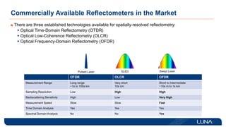
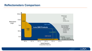
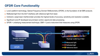
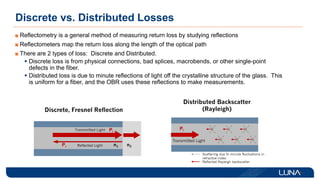
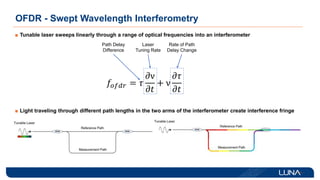
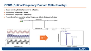
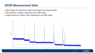
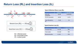
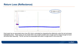
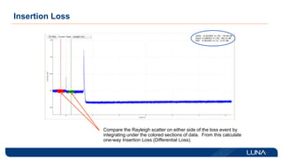
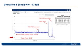
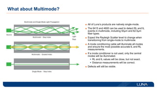
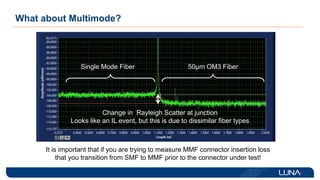
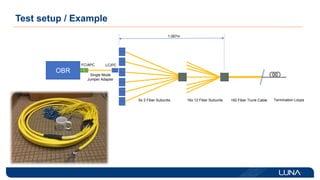
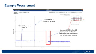
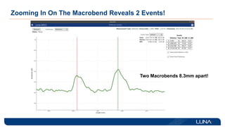
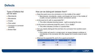
High Precision Fiber Optic Measurement Techniques:
Luna’s Optic Backscatter Reflectometer
Scott Fitzgerald
Luna Innovations
August 10, 2022
 Background of Luna Innovations
 Basics of OBR- Theory of Operation
 Measurement Definitions
 Measurement Example
 Hands-On Demonstration
Outline
Luna Innovations Overview
Luna Lightwave Division – Product Portfolio
ODiSI
OBR
OVA
Sensors - Strain, Temperature, Acceleration, Displacement, etc.
Luna 6415/6435
Polarization Measurement and Control
Lasers | Filters | Polarization | Delay Lines | Detectors | Fiber Coils
Interrogators and Software Test and Measurement Instruments
Fiber Optic Sensors Lasers, Modules, Components
ODH DAS
T-Ray
FIBER OPTIC SENSING PHOTONIC TEST
Commercially Available Reflectometers in the Market
There are three established technologies available for spatially-resolved reflectometry:
 Optical Time-Domain Reflectometry (OTDR)
 Optical Low-Coherence Reflectometry (OLCR)
 Optical Frequency-Domain Reflectometry (OFDR)
OTDR OLCR OFDR
Measurement Range Long range
~1s to 100s km
Very short
10s cm
Short to Intermediate
~10s m to 1s km
Sampling Resolution Low High High
Backscattering Sensitivity High Low Very High
Measurement Speed Slow Slow Fast
Time Domain Analysis Yes Yes Yes
Spectral Domain Analysis No No Yes
Pulsed Laser SLED Swept Laser
Reflectometers Comparison
Spatial Resolution
(includes effect of dead zone)
10 m
100 m
100 km
Measurement
Length
100 m 10-1 m 10-2 m 10-3 m
1 km
10-4 m 10-5 m
Components
Network-Level
Short Haul Networks,
Fiber Assemblies
- Avionics/Shipboard
- Intra Data Center
- Inter Rack
- Harnesses
- PICs, SiPh, waveguides
- FSS, splitters, WSS, amps, etc.
10 km
- Long Haul
- Metro
- Access
- Inter Data Center
Luna 6435
OBR 4600
Luna OBR Products
OBR 6235
Precision Reflectometers (OLCR)
Hi-Res
OTDR
OTDR
OFDR Core Functionality
Luna’s platform technology, Optical Frequency Domain Reflectometry (OFDR), is the foundation of all OBR products.
Reflected light from the DUT interferes with reference light from laser.
Coherent, swept laser interferometer provides the highest levels of accuracy, sensitivity and resolution available.
Significant core-IP developed around laser control, signal and data processing.
OFDR = underlying measurement technique; OBR = Luna’s instrument that measures using OFDR.
OFDR
Discrete vs. Distributed Losses
Reflectometry is a general method of measuring return loss by studying reflections
Reflectometers map the return loss along the length of the optical path
There are 2 types of loss: Discrete and Distributed.
 Discrete loss is from physical connections, bad splices, macrobends, or other single-point
defects in the fiber.
 Distributed loss is due to minute reflections of light off the crystalline structure of the glass. This
is uniform for a fiber, and the OBR uses these reflections to make measurements.
OFDR - Swept Wavelength Interferometry
Tunable laser sweeps linearly through a range of optical frequencies into an interferometer
Light traveling through different path lengths in the two arms of the interferometer create interference fringe
𝑓𝑜𝑓𝑑𝑟 = 𝜏
𝜕ν
𝜕𝑡
+ ν
𝜕𝜏
𝜕𝑡
Path Delay
Difference
Laser
Tuning Rate
Rate of Path
Delay Change
OFDR (Optical Frequency Domain Reflectometry)
Swept wavelength interferometry in reflection
Interference frequency  delay
Interference amplitude  reflectivity
Fourier transform converts optical frequency data to delay domain data
FFT
OFDR Measurement Data
OBR displays the reflectivity vs delay (time of flight) of an optical network
High resolution (10-80µm, depending on the OBR model)
Length limited (up to 500m or 2km, depending on the OBR model)
Return Loss (RL) and Insertion Loss (IL)
Return Loss (RL) = 10Log
Pr
Pi
Insertion Loss IL = −10Log
P𝑡
Pi
Pr = reflected power
Pt = transmitted power
Pi = incident power
Pi 1
Pr1
Pt1
Typical Reflection Return Loss (RL)
Typical RL % Light Reflected
APC-APC
Connection
-65 dB 0.000032%
PC-PC Connection -40 dB 0.01%
Open flat polish to
air
-15 dB 3%
Typical Insertion Loss (IL)
Typical IL % Light Transmitted
Connector Pair <0.2 dB 96%
Fusion splice <0.05 dB 99%
Mechanical splice 0.3 dB 93%
Return Loss (Reflectance)
Each peak has an associated return loss (RL) that is calculated by integrating the reflectivity under the red and green
highlighted areas. These areas can be made either very small to isolate only a single event or large enough to cover
the entire fiber assembly. The RL can then be associated with either a single event or the entire link.
Insertion Loss
Compare the Rayleigh scatter on either side of the loss event by
integrating under the colored sections of data. From this calculate
one-way Insertion Loss (Differential Loss).
Unmatched Sensitivity: -130dB
Luna 6235
2021
Noise Floor -130dB
What about Multimode?
All of Luna’s products are natively single-mode.
The 6415 and 4600 can be used to detect RL and IL
events in multimode, including 50µm and 62.5µm
fiber types.
Expect the Rayleigh Scatter level to change when
transitioning from single-mode to multimode
A mode conditioning cable will illuminate all modes
and ensure the most possible accurate IL and RL
measurements.
If a mode conditioner is not used, only the central
modes will be illuminated.
 RL and IL values will be close, but not exact.
 Distance measurements will be correct.
Defects will still be visible.
What about Multimode?
Single Mode Fiber 50µm OM3 Fiber
Change in Rayleigh Scatter at junction
Looks like an IL event, but this is due to dissimilar fiber types
It is important that if you are trying to measure MMF connector insertion loss
that you transition from SMF to MMF prior to the connector under test!
Test setup / Example
OBR
FC/APC LC/PC
6x 2 Fiber Subunits 16x 12 Fiber Subunits 192 Fiber Trunk Cable
Single Mode
Jumper Adapter
1.067m
Termination Loops
Example Measurement
Macrobend 1.067m from LC
Corresponds to where the
cable is furcated from ribbons
into 12-fiber round subunits
End face of LC
connector on cable
FC/APC Front Panel
of 6415
Zooming In On The Macrobend Reveals 2 Events!
Two Macrobends 8.3mm apart!
Defects
Types of Defects that
can be seen:
Macrobends
Microbends
Cracks
Poor polish
Connector to connector
variability
Broken fiber
How can we distinguish between them?
Does the event occur at a connector or in the middle of the cable?
 Macrobends, microbends, cracks, and breaks can occur in the middle of
a cable, but poor polishes or broken connectors cannot.
Is the event an IL with no associated RL?
 This often indicates bending losses. Light is escaping the core.
Is the event an extremely bright RL event (-15 to -25dB)?
 This often indicates a broken or cracked fiber.
Can you clearly distinguish the end face of a connector from another event
nearby?
 Poor polish will result in a single event; an airgap between endfaces or
microbends in the connector will often appear as 2 events close to each
other.
What are the expected RL and IL for a good connection?
RL (dB) IL (dB)
APC < -65 < 0.5
UPC < -55 < 0.5
Hands-on Demonstration: ~150m Single Mode
* Need to test UPC to air, APC to air, and Terminator.
OBR 6235
or 6435
3m
FC/APC-
LC/UPC
8 in 50m 8 in 50m 8 in 50m 8 in
Terminator*
3m
FC/APC-
LC/UPC
Key:
FC/APC:
LC/UPC:
Thank You
www.lunainc.com/

09-Luna-Fiber-Optic-Test-Measurement-final.pptx

  • 1.
    High Precision FiberOptic Measurement Techniques: Luna’s Optic Backscatter Reflectometer Scott Fitzgerald Luna Innovations August 10, 2022
  • 2.
     Background ofLuna Innovations  Basics of OBR- Theory of Operation  Measurement Definitions  Measurement Example  Hands-On Demonstration Outline
  • 3.
  • 4.
    Luna Lightwave Division– Product Portfolio ODiSI OBR OVA Sensors - Strain, Temperature, Acceleration, Displacement, etc. Luna 6415/6435 Polarization Measurement and Control Lasers | Filters | Polarization | Delay Lines | Detectors | Fiber Coils Interrogators and Software Test and Measurement Instruments Fiber Optic Sensors Lasers, Modules, Components ODH DAS T-Ray FIBER OPTIC SENSING PHOTONIC TEST
  • 5.
    Commercially Available Reflectometersin the Market There are three established technologies available for spatially-resolved reflectometry:  Optical Time-Domain Reflectometry (OTDR)  Optical Low-Coherence Reflectometry (OLCR)  Optical Frequency-Domain Reflectometry (OFDR) OTDR OLCR OFDR Measurement Range Long range ~1s to 100s km Very short 10s cm Short to Intermediate ~10s m to 1s km Sampling Resolution Low High High Backscattering Sensitivity High Low Very High Measurement Speed Slow Slow Fast Time Domain Analysis Yes Yes Yes Spectral Domain Analysis No No Yes Pulsed Laser SLED Swept Laser
  • 6.
    Reflectometers Comparison Spatial Resolution (includeseffect of dead zone) 10 m 100 m 100 km Measurement Length 100 m 10-1 m 10-2 m 10-3 m 1 km 10-4 m 10-5 m Components Network-Level Short Haul Networks, Fiber Assemblies - Avionics/Shipboard - Intra Data Center - Inter Rack - Harnesses - PICs, SiPh, waveguides - FSS, splitters, WSS, amps, etc. 10 km - Long Haul - Metro - Access - Inter Data Center Luna 6435 OBR 4600 Luna OBR Products OBR 6235 Precision Reflectometers (OLCR) Hi-Res OTDR OTDR
  • 7.
    OFDR Core Functionality Luna’splatform technology, Optical Frequency Domain Reflectometry (OFDR), is the foundation of all OBR products. Reflected light from the DUT interferes with reference light from laser. Coherent, swept laser interferometer provides the highest levels of accuracy, sensitivity and resolution available. Significant core-IP developed around laser control, signal and data processing. OFDR = underlying measurement technique; OBR = Luna’s instrument that measures using OFDR. OFDR
  • 8.
    Discrete vs. DistributedLosses Reflectometry is a general method of measuring return loss by studying reflections Reflectometers map the return loss along the length of the optical path There are 2 types of loss: Discrete and Distributed.  Discrete loss is from physical connections, bad splices, macrobends, or other single-point defects in the fiber.  Distributed loss is due to minute reflections of light off the crystalline structure of the glass. This is uniform for a fiber, and the OBR uses these reflections to make measurements.
  • 9.
    OFDR - SweptWavelength Interferometry Tunable laser sweeps linearly through a range of optical frequencies into an interferometer Light traveling through different path lengths in the two arms of the interferometer create interference fringe 𝑓𝑜𝑓𝑑𝑟 = 𝜏 𝜕ν 𝜕𝑡 + ν 𝜕𝜏 𝜕𝑡 Path Delay Difference Laser Tuning Rate Rate of Path Delay Change
  • 10.
    OFDR (Optical FrequencyDomain Reflectometry) Swept wavelength interferometry in reflection Interference frequency  delay Interference amplitude  reflectivity Fourier transform converts optical frequency data to delay domain data FFT
  • 11.
    OFDR Measurement Data OBRdisplays the reflectivity vs delay (time of flight) of an optical network High resolution (10-80µm, depending on the OBR model) Length limited (up to 500m or 2km, depending on the OBR model)
  • 12.
    Return Loss (RL)and Insertion Loss (IL) Return Loss (RL) = 10Log Pr Pi Insertion Loss IL = −10Log P𝑡 Pi Pr = reflected power Pt = transmitted power Pi = incident power Pi 1 Pr1 Pt1 Typical Reflection Return Loss (RL) Typical RL % Light Reflected APC-APC Connection -65 dB 0.000032% PC-PC Connection -40 dB 0.01% Open flat polish to air -15 dB 3% Typical Insertion Loss (IL) Typical IL % Light Transmitted Connector Pair <0.2 dB 96% Fusion splice <0.05 dB 99% Mechanical splice 0.3 dB 93%
  • 13.
    Return Loss (Reflectance) Eachpeak has an associated return loss (RL) that is calculated by integrating the reflectivity under the red and green highlighted areas. These areas can be made either very small to isolate only a single event or large enough to cover the entire fiber assembly. The RL can then be associated with either a single event or the entire link.
  • 14.
    Insertion Loss Compare theRayleigh scatter on either side of the loss event by integrating under the colored sections of data. From this calculate one-way Insertion Loss (Differential Loss).
  • 15.
    Unmatched Sensitivity: -130dB Luna6235 2021 Noise Floor -130dB
  • 16.
    What about Multimode? Allof Luna’s products are natively single-mode. The 6415 and 4600 can be used to detect RL and IL events in multimode, including 50µm and 62.5µm fiber types. Expect the Rayleigh Scatter level to change when transitioning from single-mode to multimode A mode conditioning cable will illuminate all modes and ensure the most possible accurate IL and RL measurements. If a mode conditioner is not used, only the central modes will be illuminated.  RL and IL values will be close, but not exact.  Distance measurements will be correct. Defects will still be visible.
  • 17.
    What about Multimode? SingleMode Fiber 50µm OM3 Fiber Change in Rayleigh Scatter at junction Looks like an IL event, but this is due to dissimilar fiber types It is important that if you are trying to measure MMF connector insertion loss that you transition from SMF to MMF prior to the connector under test!
  • 18.
    Test setup /Example OBR FC/APC LC/PC 6x 2 Fiber Subunits 16x 12 Fiber Subunits 192 Fiber Trunk Cable Single Mode Jumper Adapter 1.067m Termination Loops
  • 19.
    Example Measurement Macrobend 1.067mfrom LC Corresponds to where the cable is furcated from ribbons into 12-fiber round subunits End face of LC connector on cable FC/APC Front Panel of 6415
  • 20.
    Zooming In OnThe Macrobend Reveals 2 Events! Two Macrobends 8.3mm apart!
  • 21.
    Defects Types of Defectsthat can be seen: Macrobends Microbends Cracks Poor polish Connector to connector variability Broken fiber How can we distinguish between them? Does the event occur at a connector or in the middle of the cable?  Macrobends, microbends, cracks, and breaks can occur in the middle of a cable, but poor polishes or broken connectors cannot. Is the event an IL with no associated RL?  This often indicates bending losses. Light is escaping the core. Is the event an extremely bright RL event (-15 to -25dB)?  This often indicates a broken or cracked fiber. Can you clearly distinguish the end face of a connector from another event nearby?  Poor polish will result in a single event; an airgap between endfaces or microbends in the connector will often appear as 2 events close to each other. What are the expected RL and IL for a good connection? RL (dB) IL (dB) APC < -65 < 0.5 UPC < -55 < 0.5
  • 22.
    Hands-on Demonstration: ~150mSingle Mode * Need to test UPC to air, APC to air, and Terminator. OBR 6235 or 6435 3m FC/APC- LC/UPC 8 in 50m 8 in 50m 8 in 50m 8 in Terminator* 3m FC/APC- LC/UPC Key: FC/APC: LC/UPC:
  • 23.