Downloaded 1,173 times


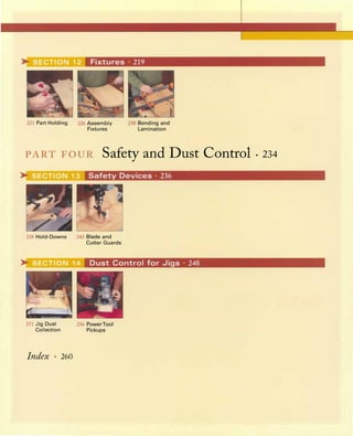

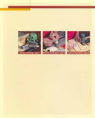

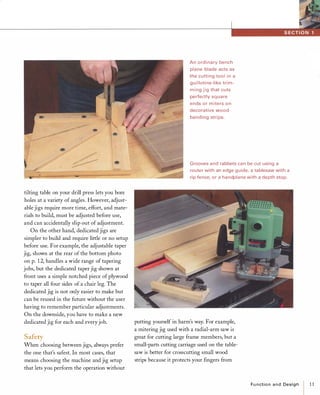
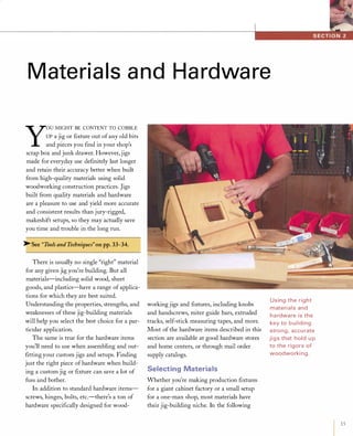
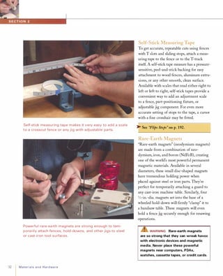
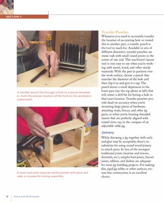
![The jig-bu ilder's a rsenal of u sefu l ha rdware i ncludes many
different kinds of fasteners, such as nails, screws, bolts,
handknobs, hanger screws, and more.
Although cut edges can splinter, vertical-grade Douglas fir is a
very stable jig-building material.
16 Materialsand Hardware
section, I'll discuss the strengths and weak
nesses of the most popular and widely avail
able jig-building materials, including natural
lumber, plywood, hardboard, MDF (medium
density fiberboard), and plastics-clear,
opaque, and slippery. Also included are
high-friction coated materials, because they
have very useful applications in jig building.
Solid Wood
When lightness and strength are key ele
ments in a jig's design, solid lumber is a valid
choice. To minimize warping and dimen
sional problems, use the most stable lumber
you can get. Kiln-dried (KD) vertical-grain
fir has straight, uninterrupted grain perfect
for making rip fences, stops, and other long,
thin jig components. On the downside,
vertical-grain fir splinters easily (see the
bottom photo at left). Poplar is somewhat
softer and less abrasion-resistant than fir,
but it's very forgiving to work with, and it's
usually cheaper than KD vertical-grain fir.
For jig parts that must be strong and wear
resistant, such as cam clamps, dense hard
woods like maple are a much better choice
than softwoods.
[TIP] You can save money by using
construction-grade lumber (preferably
with clear, vertical grain) for making big
jig parts. But dry the lumber thoroughly
before using it-about a year per inch
of thickness.
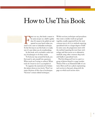
Plywood
Because ofits dimensionally stable cross-ply
construction, plywood is free of the kinds of
splitting and warping problems common to
solid woods. You can also cut strong curved
parts out of plywood without concern for](https://image.slidesharecdn.com/077989-130723102817-phpapp01/85/077989-26-320.jpg)
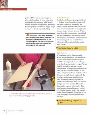
![grain direction. For this reason, plywood is
an ideal material for building jigs. However,
with its inconsistent thickness and inferior
inner veneers, standard construction-grade
plywood isn't the best choice for most jigs.
Premium plywoods such as Baltic birch,
apple ply, and maple die board are far supe
rior to construction-grade plywoods: They
are fabricated with more layers of hardwood
veneers (not softwood), and most have
thicker, clear-grained face veneers. For the
budget-conscious, shop-grade birch plywood
is also a very serviceable plywood.
[TIP] To create tight-fitting dado joints
for metric-thickness European plywoods
or American plywoods (which often devi
ate X2in. or more from their specified
thickness), use an adjustable dado set
or router bits specifically sized for under
sized plywood.
MDF
Often lumped in a category with particle
board, medium density fiberboard (MDF) is
actually a hardboard product. Although
comparable in strength and stability to
medium-density particleboard, MDF is
composed of more finely ground particles,
with 10% glue as a binder. MDF is a much
better jig-building material than underlay
ment particleboard because MDF's core is at
least 85% as dense as its faces. This makes
for clean, smooth edges that are strong and
dense enough to hold screws and other fas
teners. The dense edges also make it a terrific
template material because piloted router bits
won't compress and deform MDF edges the
way they do particleboard edges.
Because of its exceptionally smooth,
dependably flat surface, many woodworkers
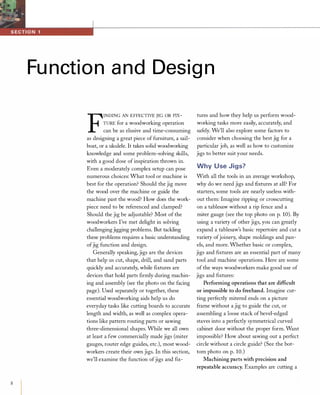
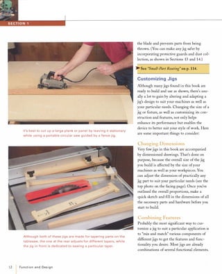
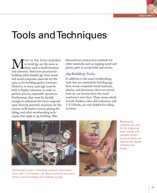
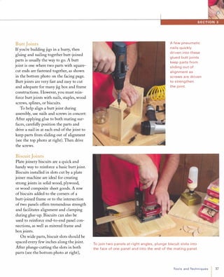
I nterior plies with knots, or voids like those shown here,
weaken construction g rades of plywood.
Underlayment-grade particleboa rd (top) is weak and flaky,
compa red to mediu m-density fi berboa rd ( M DF).
Materialsand Hardware 17](https://image.slidesharecdn.com/077989-130723102817-phpapp01/85/077989-27-320.jpg)
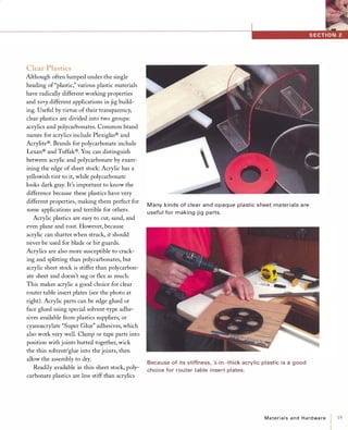
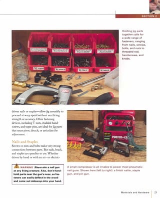
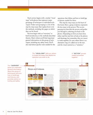
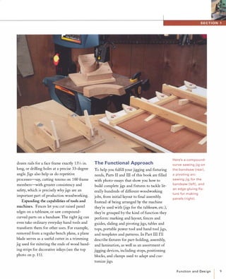
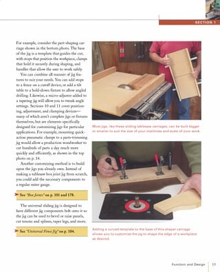
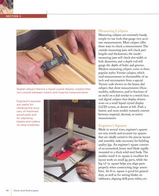
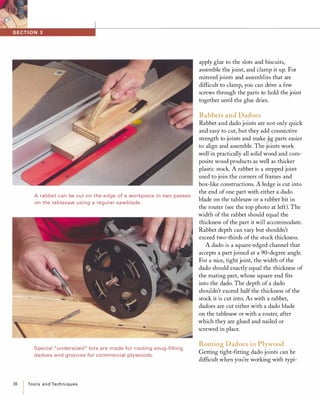
![Traditional brass and steel cabi net screws (left) req u i re
tapered pilot holes, while modern p roduction and d rywall
screws ( right) don't.
24 MateriaIsand Hardware
powered gun, these mechanical fasteners go
into place quickly and provide a reasonably
strong connection. They not only reinforce
glue joints but effectively hold parts in place
while the glue dries, eliminating the need for
clamps. This is especially handy when you're
gluing mitered or beveled parts, which can
be hard to clamp. Air-powered nail guns are
particularly useful for nailing glued parts
together, as a quick pull of the trigger drives
a finish nail or brad home before parts have
a chance to slip out ofposition.
[TIP] To keep small hand-driven nails and
brads from splitting thin wood parts,
blunt the nail's point slightly by tapping
it with the hammer before driving it in
as usual.
Wood Screws
Wood screws may be more expensive than
nails and more time-consuming to drive, but
screws have strong advantages. Not only do
they create stronger joints between wooden
parts, but they are removable. This is most
desirable when you're creating a jig from
scratch and you're not exactly sure whether it
will work as intended. Parts attached with
wood screws can be removed and reposi
tioned or replaced as needed.
""Z!S"WARNING When assembling jigs
that will be used near blades and cut
ters, use brass or bronze screws
instead of steel. That way, if a screw is
accidentally cut, it won't ruin the blade
or spray steel shrapnel.
In recent years, most serious woodworkers
have eschewed standard zinc-plated wood
screws and drywall screws in favor of square
headed production screws. Unlike drywall
screws, production screws are made from
strong, hardened steel and seldom break.
They have deep threads that offer superior
holding power, and their square-drive heads
rarely strip out, unlike slotted- or Phillips
head screws. Best of all, their cylindrical
shanks match the shape of pilot holes made
with standard drill bits, whereas traditional
wood screws require tapered pilot holes
made with a special, expensive tapered drill
bit for maximum holding power (see the
photo above). Production screws come in
steel, brass, bronze, and stainless steel and
many head styles, including flat-head,
round-head, and washer-head. Washer-head
screws are especially handy when you need
to attach a thin material like hardboard where
regular screw or nail heads might pull through.](https://image.slidesharecdn.com/077989-130723102817-phpapp01/85/077989-34-320.jpg)
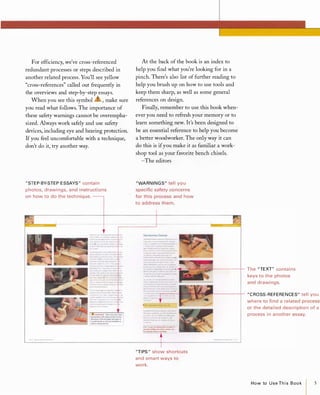
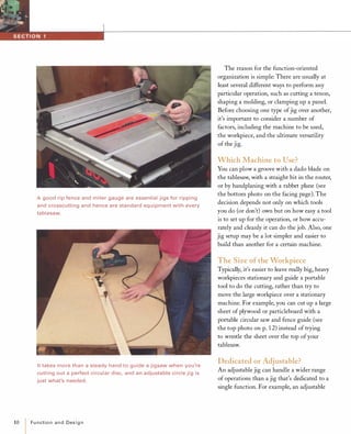
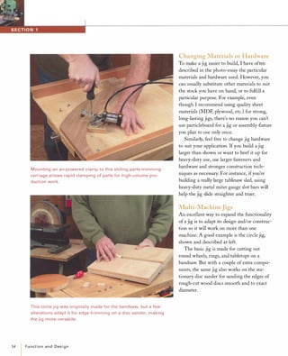
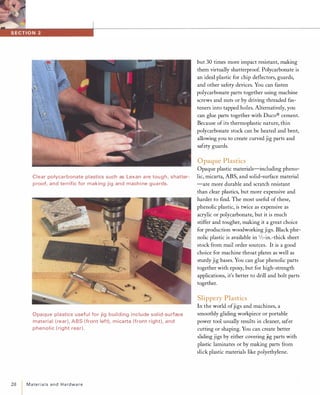
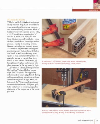
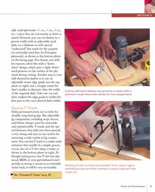
![A plastic mal let drives a T-nut i nto a hole bored
in the end of a part cut from 2x4 lumber.
Metal miter gauge slot tracks, extrusions, and
g uide bars a re all very usefu l for creating a variety
of sliding jigs.
28 MaterialsandHardware
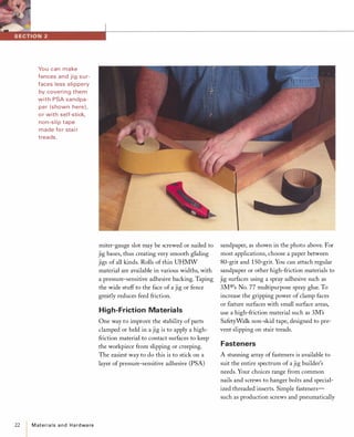
T-nuts are somewhat less versatile than
threaded inserts, but they're also less expen
sive and easier to install. T-nuts are com
monly available in sizes ranging from 10-24
size to 1/2 in. After drilling a hole that
matches the outside diameter of the T-nut
post, you simply pound the T-nut in with a
hammer or mallet. Prongs on the flange lock
it into the wood to keep it from turning. For
greatest holding strength, install the T-nut
on the opposite side of the stock so that
tightening the bolt pulls the T-nut against
the workpiece instead of away from it.
[TIP] Applying a little wax to the threads
of a threaded insert will help ease it into
the wood. This also helps with regular
screws, especially when you're driving
them into dense hardwoods.
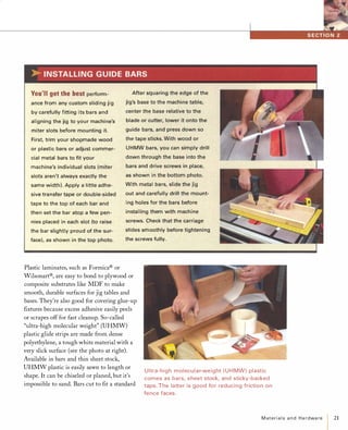
Tracks and Guide Bars
In addition to fasteners, there is a plethora
of other hardware that you can use to
quickly build accurate, versatile jigs. For
example, extruded-aluminum T-tracks come
in many shapes and sizes and offer nearly
endless jig-building possibilities. A ready-to
install track can add tremendous versatility
to adjustable jigs or clamping fIxtures. And
commercially made guide bars, as shown in
the top right photo, designed to slide in
miter gauge slots are easier to install on car
riage jigs and slide truer than shopmade
wood bars.](https://image.slidesharecdn.com/077989-130723102817-phpapp01/85/077989-38-320.jpg)
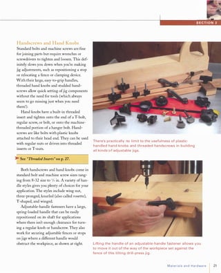
![30
Used with T-track, fli p stops a re set relative to a scale and
provide a n end stop for pa rts cut to an accu rate length.
Most miter slot track extrusions are sized to fit i nto a 1 -in.
wide slot, cut i n mu lti ple passes on a ta blesaw fitted with a
dado blade.
Materialsand Hardware
the fastener is tightened, the track prevents
the bolt head, stud, or nut in the track from
turning, allowing quick one-handed tighten
ing and loosening.
The most basic type of track for simple
jig setups has only a single T slot. The track
is installed with either screws or glue into a
simple dado or groove. Single-slot T-tracks
are unbelievably handy for creating versatile
hold-down tables as well as clamping and
assembly fIxtures.
Wider T-tracks with two or more T-slots
are designed to serve several different jigging
purposes. You can use L-shaped T-track to
create a fence for a cutoff saw, router table,
or other machine as seen in the photo at left.
Even wider extruded tracks, with four or
more slots, are useful for making high
fences, clamping jigs, and other devices. In
addition to standard T-bolts, T-nuts, or hex
head bolts, most tracks accept a wide range
of accessories, such as flip stops, micro
adjusters, and cutter guards. Flip stops are
intended to work with tracks mounted to
fences on miter gauge cutoffjigs, mortising
jigs, etc. The beauty of flip stops is that one
or more stops can be flipped out of the way
when necessary without losing their position
on the fence.
[TIP] Make sure to check whether your
desired T-track accommodates regular
hex-head bolts or T-bolts and nuts. Most
brands and styles of track accept only a
particular size and style of fastener.](https://image.slidesharecdn.com/077989-130723102817-phpapp01/85/077989-40-320.jpg)
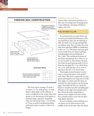
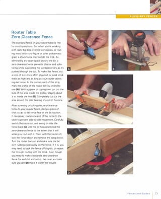
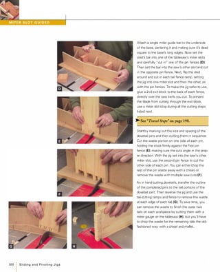
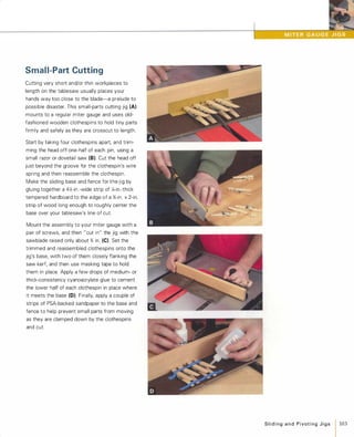
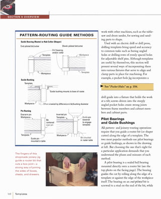
![drawing on the facing page.) Apply the
skins and then cut them out to accommo
date the router section. A lip routed in
the top opening supports an insert plate
that mounts to the router.
Gluing Up
Vibration from machine tools can make
fasteners lose their hold over time, jeop
ardizing the accuracy of a jig. Therefore,
ftxed jig parts such as non-adjustable stop
blocks and fences that must maintain
alignment should be fastened with glue in
addition to screws or nails. While stan
dard yellow carpenter's glue is just ftne for
most wood-to-wood gluing jobs, epoxy or
cyanoacrylate glues also have some very
useful applications in jig building.
[TIP] Whatever glue you use, never
glue solid wood parts wider than 4 in.
cross-grain to each other, or you risk
future joint failure due to expansion/
contraction problems.
Epoxy
Two-part epoxy glue offers terriftc versa
tility for jig building, because it bonds to
a wide assortment of materials, including
wood, composite materials, metal, and
many plastics. And it will cross-bond dis
similar materials, such as metal or plastic
to wood. Epoxy also has excellent gap
ftlling properties, so it's useful for gluing
joints that don't ftt snugly together.
There are a few things to remember
when choosing and using epoxies: First,
the 5-minute type isn't as strong in the
long run as the type that takes a full
24 hours to cure. Secondly, always dispense
The MDF pa rts of this torsion box g rid need only be joined
with g l ue and staples d riven i nto the edges of adjacent parts.
With the torsion box assem bly lying on a dead-flat su rface,
glue and nail the thin skins onto the top and bottom of the
g ridwork.
ToolsandTechniques 41](https://image.slidesharecdn.com/077989-130723102817-phpapp01/85/077989-51-320.jpg)
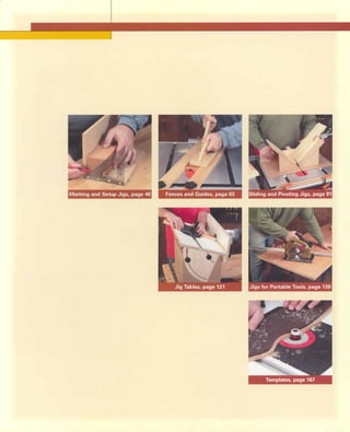
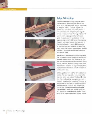
![� ��
-::..;��High bonding strength and the a bility to glue dissi milar
materials together make two-part epoxy adhesives very
versati le adhesives for building jigs.
Com monly called "super glue;' cyanoacrylate adhesives
form strong bonds and d ry almost i nstantly when sprayed
with an accelerant.
42 ToolsandTechniques
epoxy's two parts equally, and mix them
very thoroughly for at least 30 seconds
before applying. Third, for the best bond,
surfaces must be clean, and wood should
be freshly machined. Finally, let parts sit
after clamping, leaving them alone for at
least as long as the recommended set time
of the epoxy.
[TI P] Don't discard your epoxy-mixing pal
let or container after glue-up; the remain
ing glue on it will inform you when the
joint has cured.
Cyanoacrylate Glue
Commonly called "super glue" or "CA
glue," cyanoacrylate adhesive is known for
its great strength and ability to bond
many different materials. CA glues are
available in different viscosities: The thin
variety works better for smooth, non
porous materials such as metal and plas
tic, while the thick type works best for
porous woods. When sprayed with accel
erator, CA will set instantly, making it
very useful for attaching small parts that
are difficult to clamp, or for bonding thin
parts clamped atop wax paper.
�See "Mortise Template" on p.54.
CA is also great for holding hardware
in alignment while screws are installed.
To instantly bond parts together, apply
the CA to one part and spray accelerator
(sometimes called "kicker") on the other
before pressing or clamping the parts
together for a few seconds while the glue
sets, as shown in the bottom photo at left.](https://image.slidesharecdn.com/077989-130723102817-phpapp01/85/077989-52-320.jpg)
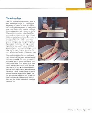
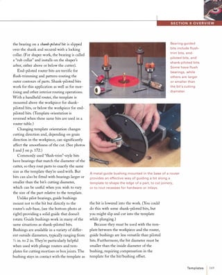
![Finishing
As with any other woodworking project,
finishing is the last step in creating stable
and durable jigs and fixtures. A quick coat
of finish on raw wood, plywood, and even
MDF and hardboard serves to protect the
wood from moisture and to reduce the
effects of humidity, which might other
wise split solid parts or warp flat panels.
A sturdy finish can also improve a jig's
wear resistance and make it easier to
clean.
In contrast to finishing furniture or
cabinets made from fine hardwoods, the
task of finishing jigs and fixtures is con
siderably less demanding. Wear-resistant
finishes are best, such as brush-on or
spray-on varnishes and polyurethanes.
My favorite jig finishes are wipe-on
polyurethanes, which have excellent dura
bility and which apply easily and dry to
the touch in 15minutes. You apply a thin
layer on the wood using a clean rag or
pad, let it soak in a bit, and then wipe off
the excess. For best results, apply two
coats (especially to open-grained woods
like oak), waiting the recommended dry
time between coats.
[TI P] On jigs made from wood parts
that have only been lightly sanded, apply
ing a wipe-on finish with a nylon abrasive
pad such as "Scotch-Brite®," will help
smooth edges and prevent splinters.
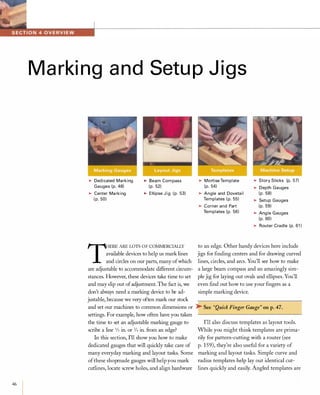
Wipe-on polyuretha n e fin ishes a re very easy to apply a n d
h e l p p rotect wood j i g parts from wear, d i rt, a n d t h e effects of
h u m i d ity cha n g es.
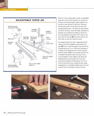
>-R ECORDI N G J I G I N STR U CTIONS
Somejigsrequire special machine setups that can be
difficult to remember over time.To save head-scratching and
searching through old
notes every time you use
the jig, it's wise to record
the perti nent setu p and use
information di rectly on the
jig as shown at right. This
might include the type of
blade or bit used, its height
or depth setting, the posi
tion of fences or stops, and
the order of operations. Note the details using a fine-point
permanent marker and then protect the information from
wearing off by coating the jig with a finish.
ToolsandTechniques
I
43](https://image.slidesharecdn.com/077989-130723102817-phpapp01/85/077989-53-320.jpg)

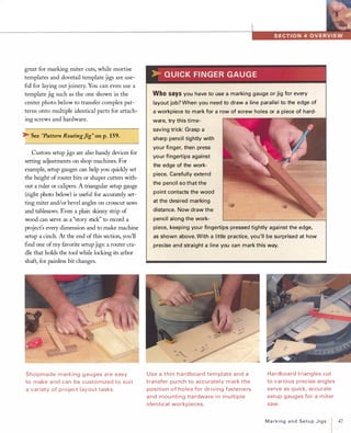
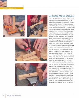
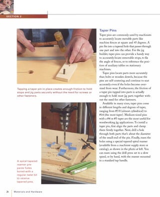
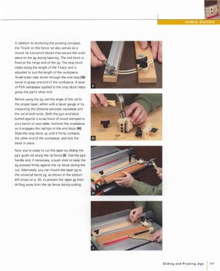
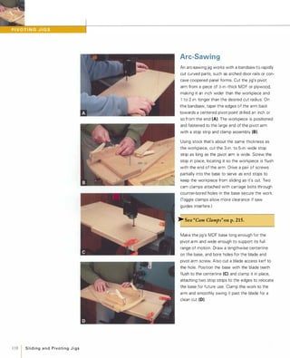
![a wedge-shaped tip that's parallel to the fence. If
a brad needs slight repositioning, you can fine
tune it by bending it or by filing its tip toward the
desired direction with a needle file (0)
You can also make dedicated marking gauges for
particular layout tasks by mounting a beam of the
desired length to a short fence. For best alignment
and strength, glue the beam into a dado cut in
the center of the fence piece (F).
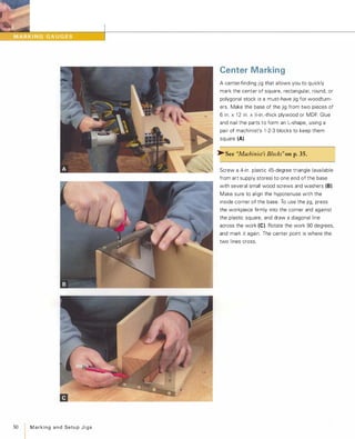
Pencil-Marking Gauges
If you prefer marking your work with a pencil line
rather than a scored line, you can make a pencil
marking gauge. Instead of driving a small nail
into a gauge's beam, drill a hole that's slightly
smaller in diameter than a round-shank pencil (A).
Locate the hole so that the distance between its
center and the fence equals the desired marking
distance. On the bandsaw, cut down the center
of the beam about an inch past the hole (8). This
kerf allows the hole to spread slightly when the
pencil is inserted, but still allows enough clamp
ing force to hold the pencil firmly in place.
�See "Quick Finger Gauge" onp.47.
[TI P] To ensure the accuracy of any
pencil gauge, make sure the pencil's point
is sharp and concentric to the shank.
MarkingandSetupJigs 49](https://image.slidesharecdn.com/077989-130723102817-phpapp01/85/077989-59-320.jpg)
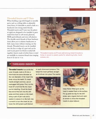
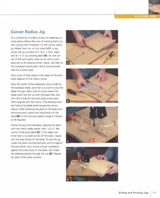
![52 MarkingandSetupJigs
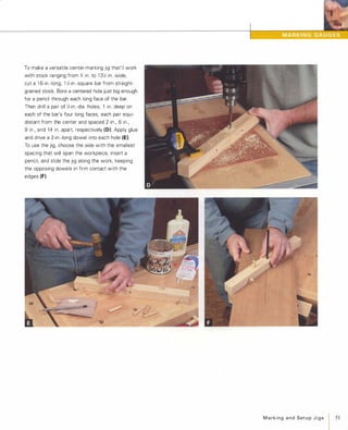
Beam Compass
A beam compass will draw large circles and arcs
for laying out tabletops, arched moldings, etc.
The beam of this compass-designed to draw
curves up to a 6-ft. radius-is made from two
strips of )':;-in. x 1 )':;-in. doorstop molding clamped
together with a pair of large notebook clips (A).
To make the compass, cut the pivot strip 42 in.
long, bevel one end to 45 degrees, and color it
with a marker pen to serve as a cursor. Glue a
3-in. square of ).:;-in.-thick plywood or MDF to the
other end for a base. Using a drill bit whose
diameter matches that of an 8d nail, drill a small
hole vertically through strip and base to accom
modate the jig's pivot point (8). Cut an 8d nail to
2 in. long with a hacksaw and then resharpen its
point with a file (e). Carefully drive the nail into
the hole.
Cut the mating strip to 48 in. long and cut another
piece 3 in. long for the pencil clamp. After sawing
a small V-groove near the end of each piece to
accommodate a pencil (0), screw the clamp and
pencil to the strip (E)
A self-stick measuring tape on the inner face of
the pencil strip allows you to quickly set the
compass to an accurate radius. You'll need the
48-in.-to-72-in. section of a tape that reads right
to left. Clip the beam strips together, set the dis
tance between pencil and pivot points at exactly
48 in., and mark a line where the beveled cursor
meets the other strip. Align the self-stick tape
with this mark (F), and you're ready to go.
[TIP] Save the leftover sections of
self-stick measuring tapes for use on
various jigs.](https://image.slidesharecdn.com/077989-130723102817-phpapp01/85/077989-62-320.jpg)
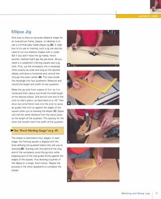
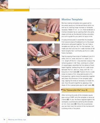
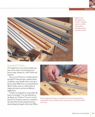
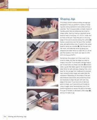
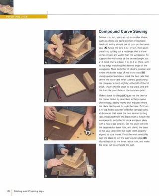
![Angle and Dovetail
Templates
It's easy to consistently and accurately mark any
angle on a workpiece using a simple marking jig
made from a piece of Yi-in.-thick hardboard and a
1 -in.-wide strip of Y,-in.-thick MDF. Take a piece of
hardboard that's long enough and wide enough
for the task at hand, and use a miter box and
handsaw or a powered miter saw to cut it to the
desired angle (A). Cut a Yi-in .-wide, 'I.-in.-deep
groove centered on the wide face of the MDF
strip, and glue the non-angled edge of the hard
board piece into the groove (8). Because the
fence overhangs both faces of the hardboard,
you can flip the marking gauge over to draw an
angle that slopes in either direction.
A dovetail-marking gauge is terrifically useful for
laying out dovetail joints to be cut by hand (e).
Start by sawing a short fence piece from Y,-in.
thick stock and a small wedge-shaped piece from
Yi-in.-thick hardboard. (Save the angled hardboard
offcuts.) Each long side of the wedge should
slope at the same angle: a taper that's between
6 and 1 0 degrees.
Draw one centerline to bisect the length of the
wedge and another to bisect its width. Clamp the
fence atop the wedge, using the angled scrap you
saved earlier, to align them (0). Put a couple of
drops of thin cyanoacrylate glue on the seam
between the parts, and spray the joint with accel
erator to set the glue immediately. Then use a cou
ple of small nails or wood screws to strengthen
the joint.
[TI P] To make a more durable angle or
dovetail gauge, make it from thin plastic
or sheet brass or aluminum.
MarkingandSetupJigs 55](https://image.slidesharecdn.com/077989-130723102817-phpapp01/85/077989-65-320.jpg)
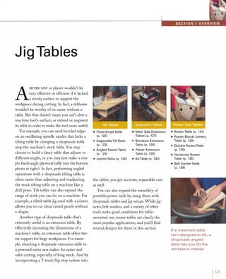
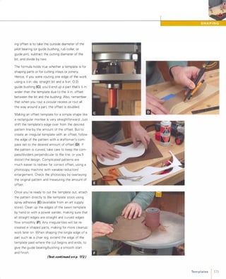
![56
I MarkingandSetupJigs
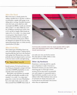
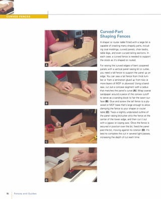
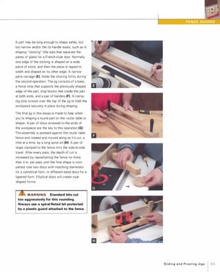
Corner and Part Templates
A corner-marking jig is useful for laying out cuts
for rounding or shaping the corners of square or
rectangular tabletops, or the top edges of a
bookcase or other cabinet project (A). First, use
a square of �-in.-thick plywood or MDF to make
a template for the corner shape you wish to cre
ate, whether it's a quarter-radius curve, an ogee,
a cove, or whatever. Saw the shape out with a
jigsaw or bandsaw, and clean up the cut with a
file or sanding block. Glue and nail a couple of
1 -in.-wide strips of solid stock to the edges of
the square on either side of the shape (8). The
strips serve as stops that will accurately locate
the template against the square corners of
your project.
Another kind of marking jig provides a template
for laying out multiple identical parts, such as
curved furniture legs or other complex parts.
Make this jig by first drawing the shape of the
desired part on J.f- or 14-in.-thick hardboard (e). Cut
the part out slightly oversized on the bandsaw,
scrollsaw, or jigsaw and then clean up the sawn
edge by sanding to the line on a disc sander for
convex edges and a drum sander for concave
edges (D). You can use the template as is, or you
may wish to glue and nail a fence strip to one
end for parts that must be laid out in a particular
orientation relative to the wood's grain (E).
[TIP] Drafting tools, such as circle and arc
templates and French curves, will help
you draw smooth, flowing lines for good
looking curvaceous furniture and cabinet
parts.](https://image.slidesharecdn.com/077989-130723102817-phpapp01/85/077989-66-320.jpg)
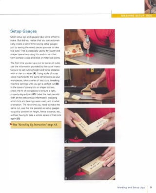
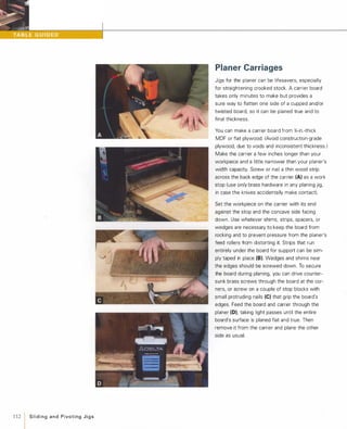
![Story Sticks
The story-stick method of setting up machines
to cut parts is simple, but powerful: All part
dimensions-the height of a bulkhead, length
of a drawer front, etc.-are marked on a single
stick, which is then used to set up fences, stop
blocks, etc., on your saws and other machines.
Any long, straight piece of solid stock or thin ply
wood makes a good story stick. You can improve
on the traditional story stick by adding a self-stick
measuring tape to it. To size the stick, cut it at
least as long as the longest part in your project.
Then saw a 45-degree bevel on one edge of the
stick on the tablesaw (A). Apply the self-stick
tape to this beveled edge, locating the zero mark
just a hair in from one end. (If you're right-handed,
you'll want to use a tape that reads right to left.)
Using a miter gauge on the disc or stationary belt
sander, trim the end of the stick until it's perfectly
flush with the zero mark on the tape (B). This
ensures that the tape will read correctly when
butted up against a fence or stop.
Now you're ready to transfer all your project part
dimensions to the story stick (e). The idea is to
write the name of the part and the relevant
dimension (thickness, height, etc.) right on the
stick, with a line or arrow pointing to its exact
dimension on the tape. Now the stick is ready to
use for setting up cuts on machinery (Dl, laying
out the position of hinges and hardware, or align
ing parts during assembly.
[TI P] You can use short story sticks to
record all the part dimensions, joinery
layout, and hardware positions of projects
built without machine tools.
MarkingandSetupJigs
I 57](https://image.slidesharecdn.com/077989-130723102817-phpapp01/85/077989-67-320.jpg)
![60 MarkingandSetupJigs
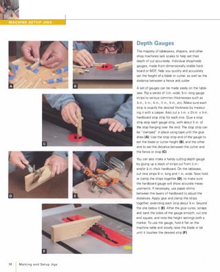
Angle Gauges
Ever get tired of taking trial cuts each time you
need to set up an odd-angle cut on the sliding
compound miter saw or radial-arm saw? It only
takes a few minutes to make an angle-setting
gauge that'll help you reset your saw's miter
and/or bevel settings the next time you need to
repeat that cut.
Make the gauge from 1l-in. or ){-in.-thick hard
board or tempered Masonite by simply cutting
out a triangle with one side sloping at the desired
angle (A). For best accuracy, use a protractor or
bevel gauge with a scale to make sure your cut is
true (8). Write the angle degrees on the gauge
and mark which corner of the triangle the angle
describes. You can also use this kind of gauge to
set angle cuts on a tablesaw. To make a gauge
easier to use for bevel settings, cut it out of 'iIi-in.
thick MDF and then drill two shallow holes along
one edge and glue a pair of Y.;-in.-dia. disc type
magnets into them. The magnets hold the gauge
firmly on the sawblade (or machine table) as you
tilt the blade (e).
To make a gauge for a compound-angle cut, com
bine two triangles-one that you've cut to the
desired miter angle, and a smaller one cut to the
desired bevel angle. With the larger triangle lying
flat on the workbench, glue the smaller triangle
on top, supported by a small glue block. Orient
the smaller triangle square to the large triangle's
angled edge (0). This gauge is very handy for
accurately setting up complex crown molding
cuts (E).
[TIP] Record all information about crown
molding cuts (type of molding, inside or
outside cut, etc.) on the angle-setting jig.](https://image.slidesharecdn.com/077989-130723102817-phpapp01/85/077989-70-320.jpg)
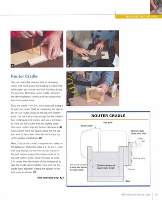
![62 MarkingandSetupJigs
One neat feature of the cradle is its built-in arbor
lock, which allows you to loosen or tighten the
router's collet using only a single wrench. Make
the lock plate from a piece of ){-in.-thick phenolic
plastic or aluminum the same width and length
as the cradle's spacer. Then cut a square notch,
centering it in the edge of the plate, and sizing it
to match the innermost arbor nut (D) Initially cut
the notch undersized and then carefully enlarge it
until it fits the arbor nut snugly. Round the top
corners of the notch slightly for easier insertion
of the arbor nut. Mount the plate to the spacer
with four washer-head screws inserted through
slightly oversized holes, which will allow adjusta
bility (E) Don't tighten the screws fully until
you're sure that the cradled router engages the
lock properly.
To use the jig, simply remove the router motor
from its base and set it into the cradle, guiding
the arbor nut into the locking plate notch (F). Try
not to overtighten the collet when installing bits.
Excessive force is unnecessary and tends to
damage the locking plate, making bit changes
more difficult.
[TIP] If your router has a built-in arbor
lock, add a plywood finger or dowel rod to
your router cradle to depress the locking
lever or button during bit changes.](https://image.slidesharecdn.com/077989-130723102817-phpapp01/85/077989-72-320.jpg)
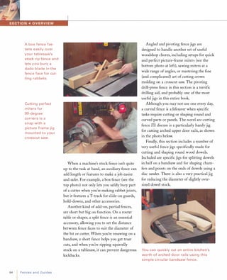
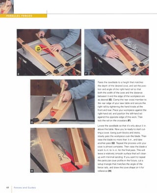
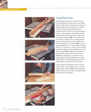
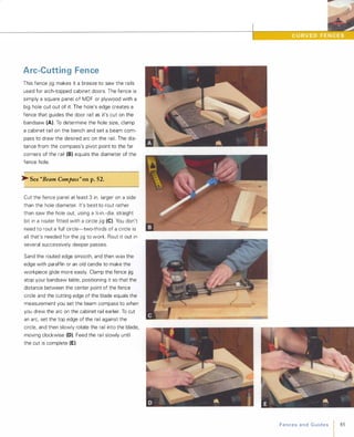
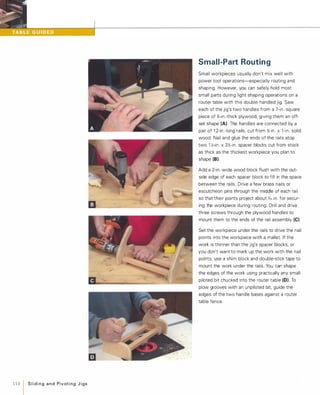
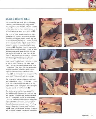
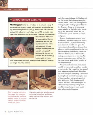
![The box fence should slip easily over your rip
fence, requiring just a quick tightening of the two
thumbscrews to keep it firmly in place (E). To
keep thin stock from sneaking underneath, slide
the box fence all the way down until it complete
ly contacts the saw table.
[VARIATION]You can make a box-style
auxiliary fence even more versatile by screw
ing on accessory strips as they are needed.
For example, installing a small strip of hard
board into a groove cut into the face of the
box (A)keeps thin stock, such as plastic lami
nates, veneers, and thin plywoods, from lift
ing up off the saw table as you cut it. Locate
the groove high enough on the fence so that
the sawblade will clear the hardboard strip.
Another time an add-on strip may be useful is
when you need to bevel an edge at an angle
greater than the maximum blade tilt of your
saw, which is typically 45 degrees. In this
case, screw a strip to your box fence's face to
elevate one edge of the work (8). The surface
of the strip is beveled at an angle that aug
ments the tilt of the sawblade so it can cut
the proper angle. For example, to rip a
58-degree bevel on the work, the sawblade is
tilted to 45 degrees and the strip is beveled at
a 13-degree angle (45 + 13 =58).
FencesandGuides
I71](https://image.slidesharecdn.com/077989-130723102817-phpapp01/85/077989-81-320.jpg)
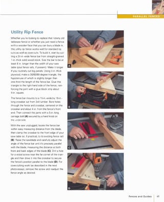
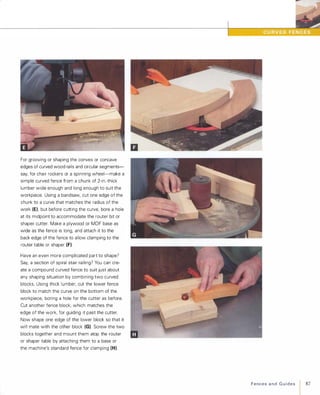
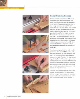
![Resaw Fence
A popular method of resawing thick stock on the
bandsaw is to use a single-point fence that
allows you to adjust the feed angle of the stock
as you saw. This way you can compensate for
"blade drift " which can cause erratic cuts. The
face of this resaw fence is actually a };-in.-dia.
dowel that was cut in half (A) using a dowel
splitting jig.
�See "Dowel-Splitting Guide" on p.88.
Cut out the fence's triangular support pieces from
};-in.-thick plywood. Size the largest triangle to suit
your bandsaw's maximum height capacity; the two
smaller triangles provide side support. Glue the
half-dowel to the edge of the large triangle using
masking tape as a clamp. Cut a 3-in. to 6-in.-wide
jig base from };-in.-thick plywood or MDF, making it
long enough to span two-thirds of your bandsaw
table. Fasten a cross member to the end of the
base that butts up against your saw's table or rip
fence rails. Glue the triangular fence to the base
(B), so that the half-dowel will align with the saw
teeth. (It's best to resaw with a };-in. to l -in.-wide
blade ) Install screws or nails through the base to
secure the fence.
Clamp the jig's cross member to your saw (e),
setting the distance between the dowel and
blade to the desired resaw thickness. Mark an
easily visible pencil line on the edge of your stock
that matches the resaw dimension; you'll use this
line to guide the stock as you saw. For best
results, use a wheeled hold-down to press the
stock securely against the fence as you work (0)
�See "WheeledHold-Down" on p.241 .
[TI P] Before resawing a thick board,
make a V-shaped mark completely across
its edge to help you realign the grain of
adjacent leaves later, if desired.
FencesandGuides 75](https://image.slidesharecdn.com/077989-130723102817-phpapp01/85/077989-85-320.jpg)
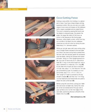
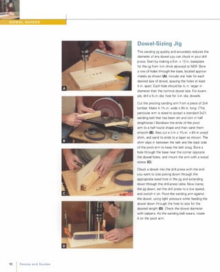
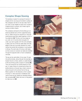
![Frame Miter Jig
Unless your power miter saw i s really accurate
and easy to set, it's more efficient to cut miters
for frames, shadow boxes, and such by leaving
the saw set for a square cut and using this frame
miter jig (A). To make the jig, first cut a base
plate from �-in.-thick plywood or MDF, making it
as long as your saw table and a couple of inches
wider than the saw's crosscut capacity. Next, rip
two 1 �-in.-wide wood fence strips from straight
grained stock and miter the end of each at
45 degrees (8).
Position and clamp the jig base atop your saw.
Then, with the saw set at 90 degrees, cut a kerf
part way through the base. Use a drafting triangle
to align one of the fence strips at 45 degrees to
the kerf, with its tip just touching the kerf, and
then glue and nail the strip in place. Using a
large, accurate framing square, position the other
fence strip at 90 degrees to the first (e), and glue
and nail it down. To strengthen the jig's base,
glue a triangular block of wood to the base at the
end of the kerf. Finally, glue and nail a couple of
cleats to the back edge of the base to allow the
jig to be clamped to the saw's fence. Whenever
you're clamping the jig to the saw, set the saw
blade in the kerf to position the jig (0).
[TI p] For perfect picture frame joints,
parallel frame members must be exactly
the same length as well as being
accurately mitered to 45 degrees.
FencesandGuides 77](https://image.slidesharecdn.com/077989-130723102817-phpapp01/85/077989-87-320.jpg)
![78 FencesandGuides
Adjustable Miter Jig
This pivoting-arm fence jig eliminates the need
for time-consuming saw adjustments in setting
up odd-angle miter cuts on a crosscut saw. Make
the base from )<2-in.-thick MDF cut to 25 in. long
and 2 to 3 in. wider than your saw's crosscut
capacity. Mark a cutline across the baseplate
5 in. from the right-hand end. Drill a hole for a
fence pivot bolt 2 in. to the left of the line and
1 )<2 in. from the back edge of the base. Counter
bore the underside of the hole to recess the
head of a carriage bolt. Next, rout the curved slot
through the base, using a router outfitted with a
X-in.-dia. straight bit and a circle-cutting guide.
Set the guide for a 1 6-in. cutting radius, and
swing it from the arm's pivot hole. Widen the
slot on the underside of the base using a
)<2-in.-dia. straight bit set for a 'k-in.-deep cut (A).
Saw a %-in. x 2-in. x 2 1 -in. pivot arm from
straight-grained stock, and then miter one end at
45 degrees (8). Then rout two X-in.-wide slots
about 1 in. long along the axis of the arm, spac
ing them 1 6 in. apart. (These allow the pivot arm
to move in or out slightly so its tip can remain
flush with the cutline.) You can cut the slots with
a router or drill press fitted with a X-in.-dia. spiral
end mill or router bit (e). Secure the pivot end of
the arm with a X-in. T-bolt and hand knob. Glue
and nail a cleat to the back edge of the base for
clamping the jig to the saw's stock fence. Cut a
kerf through the base, and use it to align the jig
to the saw when you're mounting it (D).
[TI P] PSA sandpaper stuck to a fence face
helps prevent workpieces from slipping as
they're cut.](https://image.slidesharecdn.com/077989-130723102817-phpapp01/85/077989-88-320.jpg)
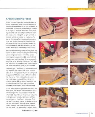
![C RO W N M O L D I N G F E N C E
Short side of jig against saw fence
Inside left and scarf joint left Outside right and scarf joint right
Outside left
80 FencesandGuides
Saw set for right-hand 45-degree miter.
Long side of jig against saw fence.
Inside right
Saw set for left-hand 45-degree miter.
sloping either towards or away from the saw fence.
The drawing at left shows the orientation of the
molding, saw and jig for each of the four basic
crown molding cuts, as well as for scarf joints,
discussed below. (For my descriptions here, " right
hand" and " left-hand " refer to the relative ends of
mating workpieces as viewed when installed. For
example, a "right-hand outside corner" actually
refers to the cut made on the left-hand end of the
right-hand workpiece.)
To cut an outside right-hand corner, set the saw
to cut 45 degrees to the right, place the short
side of the jig against the fence, and set the
molding to slope away from the fence (F). Press
the molding firmly down into the channel, holding
the channel against the saw's fence as you cut
(G). To make either an inside-right or an outside
left corner cut, flip the jig around so that its long
side is against the fence, and readjust the miter
setting for 45 degrees to the left (H). To help you
remember how to use the jig for all basic cuts,
write the information directly on the jig after you
perform each cut for the first time.
You can also use this crown molding fence jig to
cut scarf joints-sometimes necessary when join
ing two lengths of molding end-to-end (I)In a
scarf joint, the ends of the adjacent pieces over
lap each other at 45 degrees to prevent the kind
of gap you might see if the square-cut ends were
simply butted together.
[TI P] When installing crown molding
to out-of-square walls or cabinets, adjust
the saw's miter setting slightly to
compensate.](https://image.slidesharecdn.com/077989-130723102817-phpapp01/85/077989-90-320.jpg)
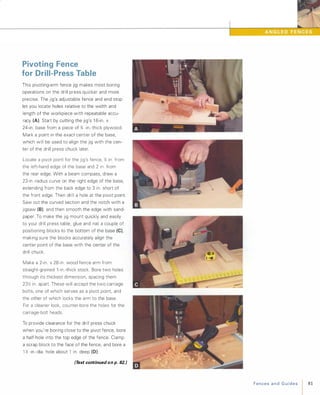
![D__�____ ____���____ �
82 Fencesand Guides
Rout a T-slot into the lower face of the fence to
accept the jig's sliding end stop. To make the
T-slot, first cut a '4-in.-wide, %-in.-deep groove,
centering it '% in. up from the bottom of the
fence. To complete the slot, re-rout the groove
using a special T-slot router bit (E). Cut a l '%-in.
x2-in. stop block from '%-in. stock, and drill it
for the T-bolt and hand knob that lock it into the
slot (F).Before attaching the pivot arm to the base, glue
a small block cut from '%-in. plywood to the
underside of the arm to act as a spacer for the
locking bolt (G). Fit a large fender washer under
the hand knob for securing the pivot arm. Use a
locking nut to secure the pivot bolt (H)
To make the jig faster to adjust to commonly set
distances-say to space holes 12 in., 1 in., 2 in.,
etc. from the edge of the work-mark the posi
tion of the fence at each distance: Measure
from the center point of the bit to the fence,
and then strike a pencil mark on the base to
mark the fence position (I).[TI P] You can make the fence on a pivot
jig slant either to the left or to the right,
depending on your personal preference.](https://image.slidesharecdn.com/077989-130723102817-phpapp01/85/077989-92-320.jpg)
![88 FencesandGuides
Dowel-Splitting Guide
This bandsaw jig i s designed to accurately slice
dowels. You can use it to cut a kerf in the end of
a dowel for using a wedged tenon, or to saw a
dowel entirely in half lengthwise (see photo A
on p. 75).
To make the jig, start by cutting a 2-in.-wide,
1 %-in.-deep V-groove down the center face of a
strip of 2x4 lumber at least a foot long, as
described in the next photo-essay on the dowel
pointing guide. On the bandsaw, cut a 1 -in.-wide
notch, positioned 3 in. from one end of the
V- block (A). Extend the notch just past the center
of the V-groove. Crosscut a 3-in. length from the
other end of the strip, flip it over, glue it atop the
strip next to the notch, and then bandsaw a %-in.
long slot precisely at the center of the V-groove (8)
to accept a kerf-alignment vane.
Make the vane by cutting a 3-in.-long section
from an old bandsaw blade with the teeth ground
off. Wrap both ends of the vane with tape until it
fits snugly in the kerf (e). Secure it in the kerf by
first drilling through the block and vane at each
end and then pinning it in place with a couple of
finish nails.
Glue the jig atop a square base cut from iii-in. or
};;-in.-thick hardboard. Clamp the jig to your band
saw table with the blade set into the notch just
ahead of and perfectly parallel to the vane. Make
a test cut on a scrap of dowel, and realign the jig
if necessary. Finally, glue a wood strip (sized to fit
your saw's miter-gauge slot) to the jig's base to
facilitate positioning of the jig for future use (D).
[TI P ] The dowel-splitting guide can also
be used to cut a kerf in the ends of square
tenons to accept diagonally placed locking
wedges.](https://image.slidesharecdn.com/077989-130723102817-phpapp01/85/077989-98-320.jpg)
![Dowel-Pointing Guide
If you have a stationary disc sander, this jig
makes it a breeze to chamfer the ends of dowels
and rods or to put a sharp point on them. The jig
has two V-grooves: one for small-diameter dow
els, and one for dowels up to 2Jt2 in. in diameter.
Make the guide from a 1 O-in.- to 1 4-in.-long block
of 2x4 lumber. On the tablesaw, cut two V-grooves
into one face of the block: one )t2 in. wide, and the
other 1 )t2 in. wide (A). The next step is to miter
the end of the block to the desired angle, which
will depend upon how sharp a point or how steep
a chamfer is desired. At the extremes, an angle
of 45 degrees will yield a more obtuse tip or
chamfer, while a 1 5-degree angle will create a
very pointy end.
After cutting the angle, glue the block atop a
1,;-in.-thick hardboard base. With a thin cardboard
spacer sandwiched between the miter face and
your sanding disc (B),glue a wooden runner
(sized to fit your sander's miter-gauge slot) to the
underside of the base. This keeps the jig aligned
while allowing it to slide back and forth to make
use of the entire sanding disk. To protect your
fingers, attach a small piece of thin hardboard to
the base (e).
To create a point or chamfer, simply place a dowel
in the groove with the end pressed against the
disc, and rotate it by hand. For more precise work,
you can fit it with a wooden stop collar, which
butts up against the end of the V-block to restrict
the thrust of the dowel against the disc (0).
[TIP] You can use the dowel-pointing
guide to put a precise point on pencils
with round shanks.
FencesandGuides 89](https://image.slidesharecdn.com/077989-130723102817-phpapp01/85/077989-99-320.jpg)
![U N I V E R S A L F E N C E J I G
T-slots for attaching
jig components
Plywood D-handle screwed
to mounting Plate)
-- ---�3/4in. x 1'/2in.
x 12in.
bottom]'
'/.-'0_,6'/,-'0_,,�'h""'" " "d
mounting plate high and wide enough to
slide on rip fence bar
104 1 SlidingandPivotingJigs
Universal Fence Jig
Unfortunately, a miter-slot-guided tablesaw jig
requires a complicated mechanism to adjust the
distance between the work and the sawblade.
This universal fence jig sidesteps that problem
by working with a standard rip fence, using the
same adjustment mechanism you use for setting
rip cuts. The jig is " universal " because it accepts
different fences, tables, stops, and accessories,
so it's useful for cutting tenons, raised panels,
splines, taper cuts (see the bottom left photo
on p. 92), and more.
Most parts for the jig are cut from plywood to the
dimensions shown in the drawing at left. The jig's
inverted U-shaped channel is sized to fit over
your saw's rip fence. Size the fit so there's about
V,6 in. of side-to-side clearance between fence
and channel; you'll shim it snug later. Before
assembly, cut two T-slots into the jig's mounting
plate, first dadoing two grooves and then finish
ing up with a T-slot bit in a router or laminate
trimmer (A).
Once the basic jig is glued and nailed together,
cut a handle from %-in.-thick plywood, tracing the
shape of your favorite handsaw's handle. Screw
it on the upper corner of the vertical plate (B)for better control of the jig. (The screws allow
removal in case the handle impedes an operation.)
Now apply a few lengths of sticky-backed UHMW
or nylon tape inside the channel to shim it to fit
snugly over the fence (e), applying more than
one layer, if necessary. Also stick the tape on the
lower edges of the jig so it glides smoothly on the
saw table.
The jig is very adept at cutting tenons. The vertical
plate provides a sturdy mount for a tall fence
that'll handle long workpieces. Make the tenon
fence by gluing a 1 O-in.-Iong straight piece of %-in.
thick stock to a 1 X-in. x 1 0-in. plywood mounting
strip that's been drilled to accept two short T-bolts](https://image.slidesharecdn.com/077989-130723102817-phpapp01/85/077989-114-320.jpg)
![that secure it in place (0). Add a small plywood
flange at the bottom of the fence to serve as a
hand rest and blade guard. Use a square to align
the fence with the saw table, and secure the
tenon fence with small hand knobs. If you wish,
add an eccentric clamp to hold long stock firmly
during tenoning (E).
� See "Cam Clamps" onp.215.
A bevel table lets you saw simple raised-panel
edges without tilting your sawblade. Cut out a
table that's a little bigger than your biggest panel,
and tack stop strips to two adjacent edges (F).
After cutting the two triangular supports that will
hold the table at the desired tilt angle, fasten them
to the back side of the table. Attach a narrow ply
wood strip to each triangle after each has been
been drilled with two holes for the T-bolts that
mount the bevel table to the fence jig (G).
By making a wooden fence with the same dimen
sions as your rip fence and clamping it to your
router table, you can use the universal fence jig
for a variety of shaping operations. For example,
you can mount a spline-cutting setup to rout slots
for dovetail splines in the corners of a box. Similar
in construction to the spline-cutting sled, this
setup involves a pair of Y.1-in.-thick plywood tables
mounted in a V configuration to a single hard
board plate that has been drilled in three places
for the T-bolts that mount it to the universal jig
(H). The V tables position the box as the jig
guides each corner past a dovetail bit (I).�See "SplineJig" onp.98.
[TI P] By slotting the holes that mount
the tenon fence to the universal jig, you
can tilt it for cutting angled tenons.
SlidingandPivotingJigs 1 105](https://image.slidesharecdn.com/077989-130723102817-phpapp01/85/077989-115-320.jpg)
![You can make a similar planer carriage to taper
the thickness of a board along its entire length.
To the bottom of the basic carrier board described
above, glue on several wedge-shaped pieces cut
to the desired taper angle (E). Set the workpiece
on top of the carrier, nearly flush with the jig's
higher end, and screw stop strips to the sled at
both ends and at the sides of the workpiece to
secure it during planing (F). Set the planer to take
only a light cut on the first pass, and then keep
reducing the planing thickness until the entire
surface of the work is cut. leaving you with a per
fectly tapered part (G).
Another kind of carriage jig for the planer allows
you to straighten and clean up surfaces and edges
on parts that are either too short or too irregular
to plane on a jointer. For the jig's base, cut a strip
of %-in.-thick MDF or plywood that's 8 in. to l O in.
wide and as long as you wish. Cut two more
strips 3� in. to 5 in. wide, depending on your
planer's maximum depth capacity. Clamp the
strips together, and drill several Y.-in.-dia. holes
along the center to accept carriage bolts. Fasten
the long edge of one of the strips perpendicular
to the base, about an inch from the edge. Place
the workpiece against the strip with appropriate
spacer blocks or wedges underneath it so that
the edge you wish to plane is parallel to and just
proud of the top edge of the strip (H). Install a
pair of bolts to sandwich the other drilled strip
against the work, thus clamping it firmly. Pass
the entire jig through the planer to take the cut (I).
[TI p] To bevel a board's entire thickness
width-wise, mount the board to a carriage
that tilts the board side to side.
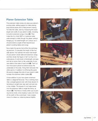
SlidingandPivotingJigs 113](https://image.slidesharecdn.com/077989-130723102817-phpapp01/85/077989-123-320.jpg)
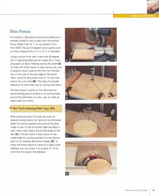
![122 JigTables
Fixed-Angle Table
This fixed-angle table will clamp to any drill-press
table to hold parts at precisely 45 degrees-the
most commonly drilled angle besides 90 degrees.
In addition, it will hold parts vertically for end
boring operations.
In profile, the table is shaped like a 45-45-90-degree
triangle. It's easy to make by simply cutting the
parts from %-in.-thick plywood or MDF, sizing
them to best suit your needs. (The table shown
here is 9 in. wide and 9 in. high.) Glue the parts
together as shown (AI, taking care to keep them
precisely aligned while you drive nails or screws
into the joints.
To facilitate securing workpieces to the table, add
a pair of aluminum T-tracks that accept adjustable
work clamps.
>- See "Extruded T-Tracks" on p.29.
Saw or rout a pair of grooves into the angled
face, sizing them to accommodate your chosen
T-track (8). To maximize versatility when you're
clamping workpieces of different sizes, the grooves
should run side to side as shown. If the T-tracks
have mounting holes, screw them into the
grooves. If not, use epoxy to glue them in place,
clamping them firmly at each end, and spanning
each with a tape-covered stick (to resist glue) to
distribute clamping pressure along the track (e).
To use the table, attach it to your drill-press table
with clamps or with bolts running through holes
or slots cut into the base. Secure the workpiece
to the angled table with a T-track clamp mounted
in each track (0)
[TI P] Filling in the irregular underside of
a drill-press table casting with plywood
makes it easier to clamp jigs and fixtures
to the tabletop.](https://image.slidesharecdn.com/077989-130723102817-phpapp01/85/077989-132-320.jpg)
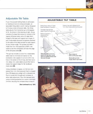
![124 1 JigTables
plywood with cleats or stop blocks (e). (Here, the
circle jig's pivot point engages a hole in the scrap
piece that's clamped over the narrow end of the
compass.) Before gluing and screwing the com
passes to the sides of the tilt table, rout a pair of
T-slots near the edges of the top to accept an
adjustable fence. Then attach the tilt table to the
front edge of the base with a pair of small butt
hinges (0).
>- See "Routing T-Tracks" on p.39.
After marking the location of the compass slot
on the edge of the base, drill a hole and drive a
threaded insert into each side to accept the
threaded handscrews (E). Finally, make a narrow
fence from '%-in.-thick stock, and drill a pair of
holes through it, spacing them to meet the slots
in the top. Fit T-bolts and handles through the
holes to attach the fence.
Secure the tilt table to your drill-press table, and
position the fence to support the workpiece so it
doesn't slip down during angled-drilling operations.
By angling the drill-press table as well as the tilt
table, you can easily drill holes at compound
angles.
[TIP] For efficiency and convenience,
make a half-dozen or so insert plates at
a time so you can replace them when
they get ragged.](https://image.slidesharecdn.com/077989-130723102817-phpapp01/85/077989-134-320.jpg)
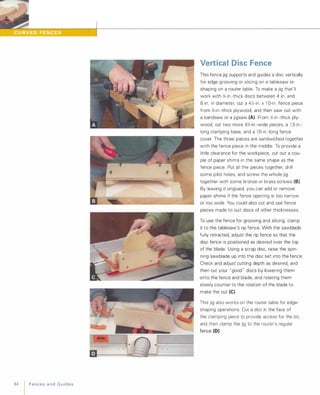
![,
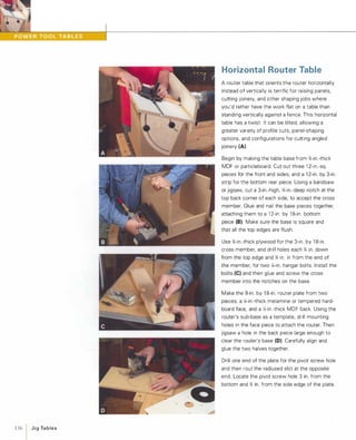
Angled Router Table
Here's a simple auxiliary table that tilts the
workpiece 45 degrees relative to your router
table top. It's handy for angled routing, such as
when you need to create an angled slot, shape
a raised panel edge, or cut a finger groove for a
drawer pull using a bullnose router bit (A).
Start by cutting a piece of �-in.-thick plywood or
MDF that's as long as your router table's top and
about 1 2 in. wide. Gauge a line 1 in. in from one
edge, and then bore two overlapping 1 -in.- or
1 �-in.- dia. holes near the line's midpoint, spac
ing them approximately as shown (8). Now rip
the piece along the line to separate a 1 -in.-wide
strip, which will serve as the ledge to support
the workpiece. Cut a shallow sawdust clearance
groove in the table just where the ledge meets
it, and glue and nail the two strips together,
matching the position of the holes (e).
For supports, saw a pair of right triangles from
�-in.-thick stock, with the hypotenuse cut to the
angle of desired tilt. Also cut a clamping strip
2� in. wide and a few inches shorter than the
length of your tilt table. Working on a flat bench
top or machine table, carefully glue and nail the
triangles to the ends of the clamp strip, and then
attach the tilt table (0)
Secure the tilt table to your router table fence
with a pair of C-clamps, positioning the hole in
the top at the location of the router bit. This
way, you can reposition or lock down the tilt
table using your router fence's existing hardware.
[TI P] When boring with large-diameter
Forstner® bits, slowing down the RPMof your drill helps the bit run cooler and
cut more cleanly.
JigTables / 125](https://image.slidesharecdn.com/077989-130723102817-phpapp01/85/077989-135-320.jpg)
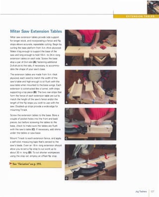
![130 I JigTables
Air Table
An air table is a big, thin, perforated box that
releases a cushion of air to allow heavy panels to
glide over it with little effort. It's useful as an out
feed table for a tablesaw or other machine. The
table is built like a torsion box. The one shown
here is 3Y2 in. x 24 in. x 72 in , but you can make
it any size you wish. After sawing the long sides,
the central support ribs, and the inner strips,
bore holes through all the inner strips and ribs
(A) to allow the air to circulate inside the box.
The top and bottom skins are cut from }4-in.-thick
single-sided melamine panel, with the melamine
surface oriented to the outside of the box. The
air holes in the top are drilled in a 2Y2-in.- x 2Y2-in.
grid pattern with a :4-in.-dia. drill bit (8). Spacing
isn't critical; just plan the grid layout so that
holes aren't blocked by the inner structure.
As for any torsion box, assembly is best done on
a large, flat surface. For long tables like this one,
glue and nail components in sub-assemblies (e),then put the sub-assemblies together, applying
the top and bottom skins last.
Air is supplied to the table from a 3 hp-5 hp shop
vacuum's blower port, which is connected to a
plastic hose fitting mounted over a hole cut into
the bottom center of the air table. Mount the
table atop a pair of sawhorses or adjustable
stands set next to your saw, aligning the table
flush and level with the saw table (0).
[TI P] Your shop vacuum can do double
duty when you're using the air table
with a benchtop-style tablesaw: Connect
the blower hose to the air table and the
vacuum hose to the saw.](https://image.slidesharecdn.com/077989-130723102817-phpapp01/85/077989-140-320.jpg)
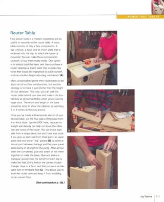
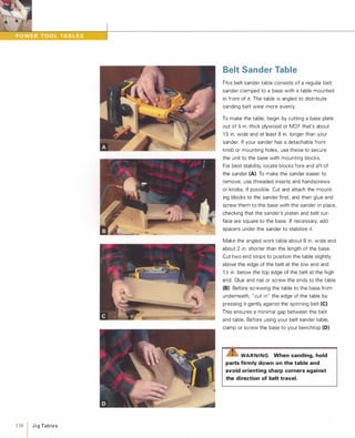
![132 1 JigTables
Hinging the router tabletop to the base makes it
much easier to adjust and change router bits. First,
make a support rod for the top from a sturdy dowel
and screw it to a block of wood mounted inside
the front edge of the table (0). To hinge the top,
use butt hinges with removable pins. Set the top
on the base, mark the hinge positions carefully,
and then use a self-centering bit and drill to bore
the holes, using the screw holes in the hinges as
a guide. Remove the pins and screw the hinge
sides to both the top and base (E). Set the top
back in place and drive the pins home, and then
mark and drill a shallow hole on the underside of
the top for the dowel support rod.
To make your table safer and easier to use, pur
chase and mount a button-type on/off switch to
the front of the base. Wire it to an electrical box
fitted with a receptacle (to plug the router into)
and mount it to the base (F). Attach your router
to the insert plate, drop it into its recess in the
top (G), plug it in, and you're ready to rout.
[TIP] You can use your router table with a
jigsaw, portable spindle sander, or other
power tool by making a custom insert
plate that secures the tool underneath.](https://image.slidesharecdn.com/077989-130723102817-phpapp01/85/077989-142-320.jpg)
![The Y.-in.-wide compass slot is routed with a
1 6Y.;-in. radius centered on the pivot hole. Mount
the plate with a pair of threaded handscrews (E).
Loosening the handscrew on the plate lets you
adjust the distance of the router bit relative to the
table surface.
Lay out the two compasses, which support the
tabletop and allow it to tilt. Both are cut from a
single Y.;-in.-thick plywood blank. Temporarily
screw the blank to scrap plywood, and attach
scrap blocks to provide pivot points for a router
trammel (F). Rout all four slots at the radiuses
shown in the drawing at right. and then cut the
compasses from the blank.
Next. cut the 1 4-in. by 22-in. tilting tabletop from
%-in.-thick melamine or MDF, beveling the under
side of its rear edge at a 45-degree angle, for
clearance when tilted. Plow two y';-in.-wide, %-in.
deep dadoes into the underside of the top (G).
Space them exactly 1 3y'; in. apart, so that the
inside faces of the compasses will be flush
against the sides of the base. If you plan to use
a miter gauge with the table, plow a groove for
the track now.
Glue the compasses into their dadoes, aligned as
shown in the drawing at right. Finally, install four
threaded inserts on the sides of the base to
accept the studded handscrews that secure the
top at an angle. Set the top-and-compass assem
bly on the base, bringing the top's beveled edge
against the router plate. Mark the upper end of
each compass slot and drill on those marks for
the threaded inserts. Then install the studded
handscrews (H), and you're ready to rout.
[T I P] To keep parts aligned during assem
bly, drive in small brads and then clip their
heads off nearly flush. The projecting
nibs keep the slippery glued surfaces
from sliding while clamps are tightened.
C O M PA S S LAY O UT F O R T I LT TA B L E
3/4-in.
tilt-table Compass set into
top 3/B-in.-deep dado
inserts for
lock knob
MDF base
Router plate
through compass
JigTa b l es 1 137](https://image.slidesharecdn.com/077989-130723102817-phpapp01/85/077989-147-320.jpg)
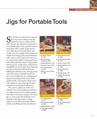
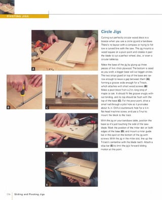
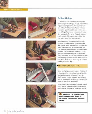
![Crosscut G uide
Sometimes when cutting lumber for shop furniture
or backyard construction projects, you just need a
quick crosscutting guide. This one will help you
accomplish both square and 45-degree miter cuts
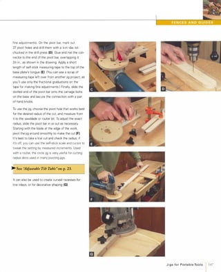
using a regular portable circular saw. For the jig's
fences and crossbar, cut three 20-in. lengths from
%-in.-thick, 2:t.;-in.-wide solid wood stock. Plow a
:4-in.-deep, 2:t.;-in.-wide dado on the underside of
the square-cutting fence 6 in. from one end, and
dado the bottom of the miter fence at 45 degrees
in each direction (A).
Miter one end of the crossbar so it comes to a point
(like a fence picket). One end of both the miter
fence and pointed crossbar is drilled and joined with
a carriage bolt and hand knob so that the fence will
pivot 45 degrees in either direction (8). Glue the
other end of the crossbar to the dado in the square
cutting fence. With a jigsaw or bandsaw, cut a han
dle for the jig from a 9-in. x 4:t.;-in. piece of %-in.-thick
plywood (e).The twin handle extends in each direc
tion to allow both right- and left-handed cuts. Attach
the handle to the center of the crossbar with screws
from underneath. To use the jig, pull the crossbar
tight against either edge of the stock with one hand,
and use the appropriate fence to guide the saw
through the cut (0) For 45-degree cuts, pivot the
miter fence as necessary.
[TIP] Rub a little wax onto the edge
of any wood fence or guide to help tools
glide more smoothly along the edge.
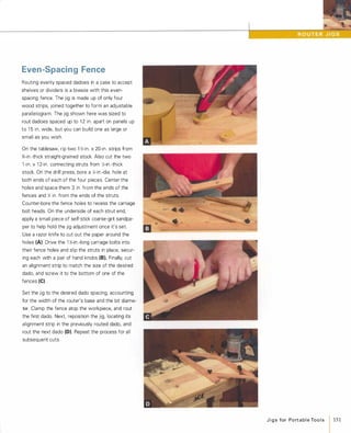
JigsforPortableTools
1 141](https://image.slidesharecdn.com/077989-130723102817-phpapp01/85/077989-151-320.jpg)
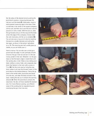
![you'd like to occasionally remove the bar to make
angled cuts, then fit it with a spline and T-nut or
T-bolt as you did the stop block. In either case,
screw another small quick-action clamp to the
crossbar, centered on the T-slot (E).
Clamp the fence to your workbench and "cut in"
the hardboard baseplate, trimming it exactly flush
with the blade teeth (F). This allows you to position
the jig on the workpiece simply by aligning the
baseplate with your cutline. To use the fence, posi
tion it atop the work with the crossbar pressed
firmly against the edge of the panel. Slide the stop
block tight against the opposite edge of the work,
tighten the handscrew, and engage the quick
clamps at both ends. Make sure to keep the saw's
base firmly against the fence as you cut (G).
Even though the baseplate is trimmed for use with
a particular circular saw, you can still use the oppo
site edge of the fence to guide a router or jigsaw.
To facilitate setup, make a spacer strip from thin
hardboard (H). Its width should equal the distance
from the edge of the power tool's base to the near
edge of the cutter or teeth.
[TIP] To keep the slide-on crossbar per
fectly square to the fence, drive a screw
through the baseplate into the crossbar.
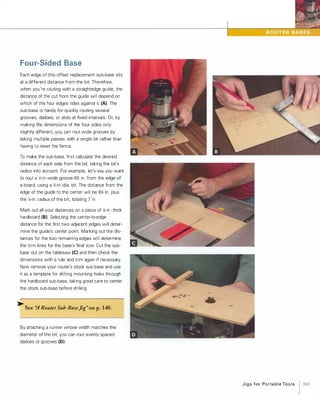
JigsforPortableTools 143](https://image.slidesharecdn.com/077989-130723102817-phpapp01/85/077989-153-320.jpg)
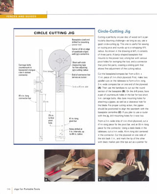
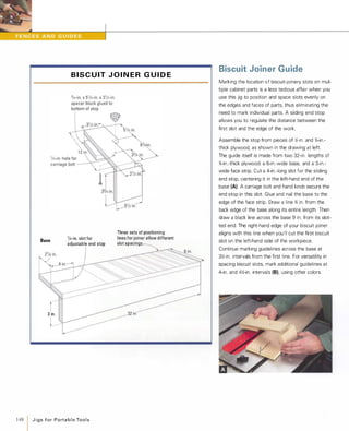
![Crosscut Jig
This jig allows you to crosscut and miter panels up
to % in. thick and 24 in. wide using a portable circu
lar saw (A). You'll size this guide rail assembly to
accommodate the width of the saw's baseplate.
Begin by cutting a pair of 45-in.-long, 1 �-in.-square
pieces for the side rails. Then make a 1 �-in.-thick
x 3-in. pivot block that's exactly as long as your saw
base is wide. Also make an end piece that's the
same length, but 1 �-in. square. Join these parts
atop a 45-in.-long strip of ;4-in.-thick hardboard,
gluing and nailing or screwing the entire assembly
together (8).Also cut a %-in. x 3�-in. support block
that's as long as the width of the rail assembly, and
glue it to the underside at the far end.
Clamp the completed assembly to sawhorses, and
"cut in" the base plate with your circular saw. Drill
a o/,6-in.-dia. hole through the pivot block, in line with
the saw kerf and centered across the width of the
block. Make a 48-in.-sq. baseboard for the jig from
%-in.-thick MDF or plywood, and mark a pivot point
1 6 in. from the baseboard's left side and 1 �-in. from
its back edge. From this point, use a circle jig (see
"Circle-Cutting Jig" on p. 1 46) set to a 42-in. radius
to rout a ;4-in.-wide arcing slot across most of the
panel. Glue and nail a 3-in.-wide fence 6 in. from
and parallel to the back edge of the baseboard, and
a 6-in. x 6-in. riser block centered over the pivot
hole. Drill through the block and baseboard at the
pivot hole, and then attach the guide rail with a car
riage bolt (e).Use another carriage bolt and a hand
knob to lock the angle of the rail at the opposite
end (0).
[TIP] For frequently used angles, add
stop blocks or mark angles on the jig's
base.
JigsforPortableTools
1 145](https://image.slidesharecdn.com/077989-130723102817-phpapp01/85/077989-155-320.jpg)
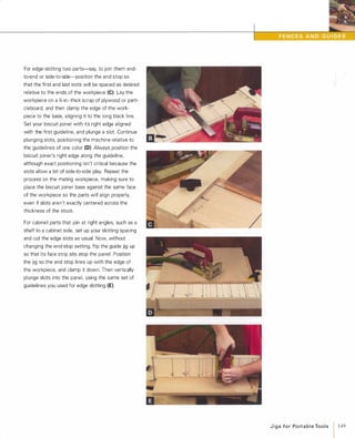
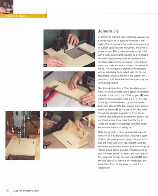
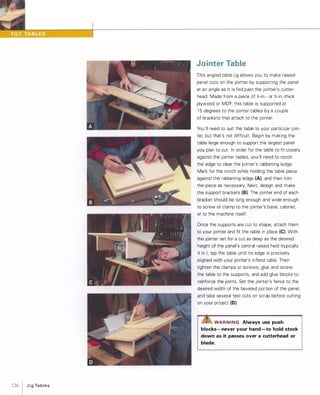
![Glue and nail all the jig base parts together, taking
care to keep the top perfectly square to the work
support (0) by gluing the triangular gussets in
place. Once the assembly dries, attach the tem
plate support to the top with short carriage bolts
and small hand knobs. Now screw the hardboard
template (made as described in Section Nine) to the
top with four or five short screws (E). Cut a 1 �-in.
x1 2-in. workpiece fence from '%-in.-thick stock, and
miter its left-hand top corner. Rout a pair of �-in.
wide, l-in.-Iong centered slots through the fence,
spacing them to match the slots in the work sup
port. (The mitered corner and mounting slots allow
the fence to be tilted when necessary.) Mount the
fence to the jig base with a pair of �-in. carriage
bolts inserted through the slots and secured with
hand knobs (F)Finally, bolt a large quick-action
clamp (screwed to a spacer block) to the right-hand
side of the work support.
Clamp the workpiece in place, adjusting the fence
so the work is positioned side-to-side as desired
under the template. Then adjust the template sup
port to reposition the template as necessary to
make the desired cut. To prevent chip clogging, it's
best to clamp the work so its top end is slightly
below the template (G). You can also rout joinery
on curved or irregularly shaped pieces by making a
fence that matches the shape of the workpiece (H).
[TIP] To rout a mortise into the edge
or face of a workpiece, use the jig without
a fence.
J i g s for Po rta b l e Too l s
1 153](https://image.slidesharecdn.com/077989-130723102817-phpapp01/85/077989-163-320.jpg)
![158 J i g s for Po rta b l e To o l s
strips to reinforce the joint. With the units still
clamped, drill a pair of holes near the bottom of
each side into the base. Then remove the clamps,
raise the sides up on a couple of 1 Y,>-in.-thick scraps,
and drill another set of holes through the sides (D).
The holes allow you to set the height of the router
at a higher or lower position, to suit either small- or
large-diameter turnings.
Make the runner that guides the carriage, ripping a
1-in.-thick hardwood strip wide enough to fit snugly
between the lathe's rails without binding. Screw it
to the underside of the base, making sure to align
the router collet centerline along the lathe's spindle
centerline (E). Before routing, prevent the work
piece from turning by securing it with the lathe's
built-in spindle lock or a shopmade index plate.
With a bullnose or corebox bit chucked in the
router, plunge the bit into the turning, and then
slide the carriage along the lathe bed (F)For rout
ing tapered spindles, clamp a pair of tapered wood
shims (cut to match the taper angle of the turning)
to the lathe bed (G).
[TIP] When routing multiple flutes or
reeds, you'll get more uniform results
by clamping stops to your lathe's bed to
limit carriage travel.](https://image.slidesharecdn.com/077989-130723102817-phpapp01/85/077989-168-320.jpg)
![162 1 J i g s fo r Po rt a b l e Too l s
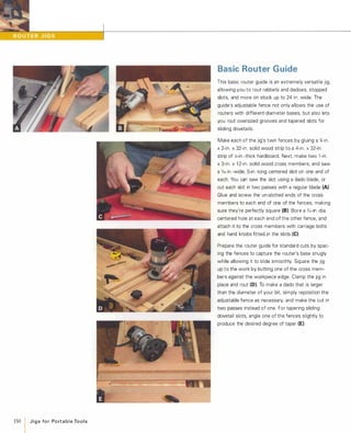
Self-Centering Base
This router guide centers mortises and slots on the
edges of frame members. Its twin fences allow
routing right up to the end of the workpiece (A).
The base is made from a piece of 1,;-in.-thick hard
board cut to 6% in. x gYz in. Mark the center point,
and then draw a line through it across the width of
the piece. Mark points on the line 1 1,; in. on either
side of center. With a compass leg on one of the
points, draw a 4%-in.-radius edge-to-edge across
the width of the piece on one end. Then repeat the
procedure, swinging the compass from the oppo
site point. Bore two 1,;-in.-dia. countersunk holes at
those points for attaching the fences and then bore
a centered hole for the router bit. Mount the base
to your router, as shown on p. 1 40, and then band
saw the ends of the base along the radius lines (8).Make two %-in. x 1 1,;-in. x 1 2-in. solid-wood fences,
and bore a 1,;-in.-dia. bolt hole through the thicker
dimension of each piece, centered along its length.
Next, install a 1,;-in. hanger bolt 1 76 in. from one end
of each piece, adding fender washers and small
hand knobs. Glue a small hardboard shim to the
end of each fence next to the hanger bolt, and
attach each fence to the base with a 1,;-in. x 2-in.
long flat-head machine screw (e).To set the guide, place it over the workpiece and
pivot the fences until they're in full contact with the
workpiece (D), and then lock the hand knobs.
[TI P] You can rout off-center mortises
by shimming the inner face of one of
the fences.](https://image.slidesharecdn.com/077989-130723102817-phpapp01/85/077989-172-320.jpg)
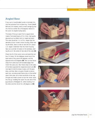
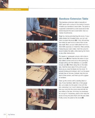
![Shooting Boards
A shooting board is used to guide a handplane
when you're trimming the ends of mitered frame
members and other parts. The board's sturdy twin
fences support stock accurately at either a 45- or
90-degree angle as the handplane (lying on its side
and sliding along a straight guide) is pushed past,
trimming the part to a precise angle.
Start by cutting out a 'ill-in. x 1 O-in. x 24-in. base and
a �-in. x 5-in. x 24-in. straight guide from MDF or
plywood. Glue and nail the guide atop the base.
Cut the 45-degree and 90-degree fences for the
shooting board from kiln-dried solid stock at least
1 � in. thick. Avoid green construction lumber, which
is likely to warp and crack as it dries. Cut a 5-in.-high,
45-45-90-degree triangle for the 45-degree fence (A),
and a 2-in. x 5-in. piece for the 90-degree fence.
Make sure that the bearing edges of the fences are
absolutely straight and square. Mount the fences to
the straight guide with large wood screws set into
countersunk holes (8).It's best to screw the fences
down and check their alignment with an accurate
try square and miter square, and then glue and
screw them back in place. Stick PSA-backed sand
paper to the face of each fence (e)to keep work
pieces from slipping.
To use the shooting board, hold the workpiece firmly
against the appropriate fence, with just a bit of the
end overhanging the straight guide. Trim the end
using a square-sided bench plane with a razor-sharp
blade set for a very light cut (0).
[TIP] For accurate shooting, make sure
the sides of your bench plane are
perfectly square relative to the sole.
J i g s fo r Po rt a b l e Too l s
1165](https://image.slidesharecdn.com/077989-130723102817-phpapp01/85/077989-175-320.jpg)
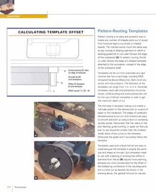
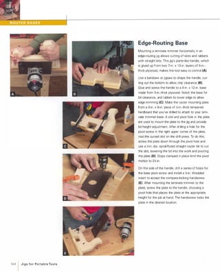
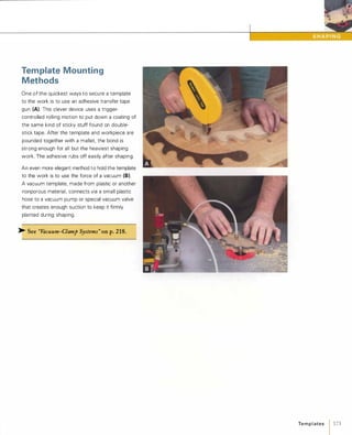
![172 Te m p l ates
Rough-cut the workpiece to approximate shape
so the bit/cutter doesn't need to hog off tons of
material. Then attach the template using double
stick tape, small nails, or other methods (see
"Template Mounting Method" on the facing
page) (G). For thick or heavy parts, screws hold
better.
Parts large enough to clamp flat atop a work
bench are most easily routed freehand (H). For
smaller parts, it's best to use a router table or
shaper and, if possible, to incorporate the tem
plate into a baseplate jig.
>- See "Baseplate TemplateJigs" on p.1 74.
The template/workpiece is oriented either facing
up or down, depending on whether the guide
bearing is above or below the cutter. When
template-routing curvy parts and splintery woods,
you'll get cleaner edges with less tearout if you
use a flush-trim bit fitted with two pilot bearings,
one on the end, and one on the shank (I). This
allows you to flip the template/workpiece over,
and rout favoring the grain direction as it changes
in different sections (J).
[TIP] To template-rout two parts at once,
use thick stock and then resaw it in half
after routing.](https://image.slidesharecdn.com/077989-130723102817-phpapp01/85/077989-182-320.jpg)
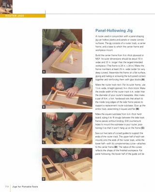
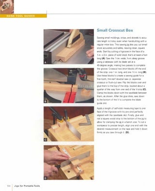
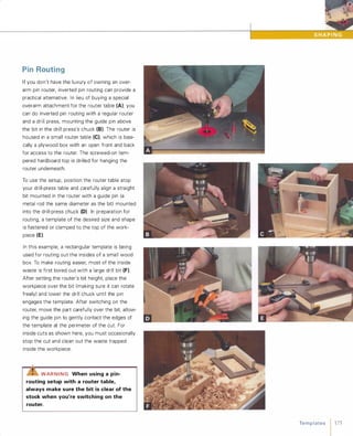
![174 1 Te m p l ates
Baseplate Template Jigs
What's easier than shaping a part with a router
and template? Using a jig that incorporates the
template as part of a jig that positions and clamps
the workpiece atop the template with no other
fastening required. Baseplate template jigs used
with a router table (A) or shaper are so efficient
that they're a mainstay for production woodwork
ers. The only limitation is that you can't use a
baseplate template for shaping parts all the way
around.
Start by cutting out a template for the desired part
shape, as described previously. Make the tem
plate at least a couple of inches wider than the
part to leave room for the stops and clamps.
Extending the edges of the template a little at
both ends gives the bearing or collar support at
the start and end of cutting, resulting in a cleaner
cut part. Attach stop blocks that were cut from
stock the same thickness as the workpiece to the
top of the template, driving nails or screws in from
underneath (8). Locate the stops so they'll properly
position the work blank relative to the shaped
template edge.
To hold the part firmly, you can use eccentric
clamps, cam clamps, or quick-action clamps (e).For smaller jigs, adding a holding plate to the
clamp head and covering the surfaces with PSA
sandpaper helps the part stay put during shaping
(see the bottom photo on p. 1 67). On larger jigs,
add a pair of handles for better safety and control.
With the rough-trimmed part clamped in place,
flush-trim the edge of the part using a bottom
piloted bit or cutter. By changing bits/cutters, you
can also use the baseplate template jig to further
shape the part's edge, perhaps to rout a cUNed cab
inet rail for cope-and-stick joinery, for example (0).
[TIP] When template routing, save
time by stacking blanks and sawing out
several rough-cut parts at the same time
on the bandsaw.](https://image.slidesharecdn.com/077989-130723102817-phpapp01/85/077989-184-320.jpg)
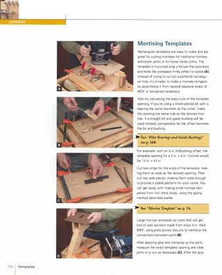
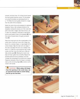
![dries, trim the template ends square and flush.
You can clamp the template directly atop the
work, mount it to a simple, box-like fixture that
clamps to the workpiece (D), or mount it to a
more elaborate clamping fixture, like the one
shown in the top photo on the facing page. You
can either square up the rounded corners of routed
mortises with a chisel, round over the tenon
edges, or use loose splines.
� See ''Routing Fixtures" onp.222.
A router and template are also great for creating
recesses or sockets for inlays and hardware. A
small template with a rectangular opening is very
handy for routing shallow mortises for butt
hinges (E). Gluing a pair of stop strips to the bot
tom of a hinge template will align and space the
template so the hinge recess is routed in the
right place on the workpiece. The strips also
provide a handy way of clamping the template to
the work.
Inlay templates may be practically any shape:
polygonal, curved, or irregular. For symmetrical
forms, you may employ the same method used
for making rectangular templates. The diamond
shaped inlay as shown here (F)has 50-degree
mitered angles cut on the two pieces that make
up the ends of the template. Clamp the template
atop the work surface and rout, using a shank
piloted or guide-bushing-guided straight bit (G).
You can also use template routing to cut the
35mm sockets required for mounting European
style cabinet hinges. After calculating bit offset,
use an adjustable fly cutter to bore a hole in the
template stock (H). Add a stop strip to space the
hole relative to the edge of the work, and rout as
you would for any other mortise (I).[TI p] If necessary, shim the edges of a
template with masking tape to reduce the
dimensions of a routed mortise or inlay.
Te m p l ates 1 177](https://image.slidesharecdn.com/077989-130723102817-phpapp01/85/077989-187-320.jpg)
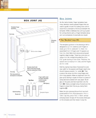
![fixture (D), aligning it so that the fingers protrude
1 Y.1 in. past the face of the clamping board. Nail
and glue a 2Y.1-in.-wide end strip to the left side of
the fixture, as shown in the drawing on the facing
page. Screw the end stop-a B �-in. x 1 0Y.1-in. strip
of Y.1-in.-thick plywood-to the front of the end
strip using washer-head screws driven into over
sized holes that allow a little side-to-side adjust
ment. Position the stop so that its edge is /16 in.
from the inside edge of the first finger and per
fectly square to the template. To clamp parts
more quickly and easily, mount a quick-action
clamp to the end stop, positioning it far enough
below the template to clear the router bit.
Secure the template fixture to your workbench
by clamping the end strip into a bench vise.
Clamp the first workpiece into the jig, making
sure it's set flush to the end stop and against the
underside of the template. Set the router bit to
cut very slightly deeper than the thickness of the
workpiece, and slip the guide bushing in
between the first set of fingers to take a cut.
Work your way along the template to complete
cutting the first half of the joint (E) To make the
other half of the joint, offset the mating work
piece relative to the template by positioning a
Y.1-in .-thick spacer against the end stop (F)Rout
as before, and your box joint is ready to assem
ble. You can quickly cut box joints in stock up to
Y.1 in. thick by routing both pieces at the same
time. Simply clamp both workpieces into the jig,
one on top of the other, offset by the spacer
strip as shown (G).
[TI P] Check the fit of joints produced by
a finger template jig before gluing it up:
Dry-clamp the template and carefully rout
a test part.
•
Te m p l ates 1 179](https://image.slidesharecdn.com/077989-130723102817-phpapp01/85/077989-189-320.jpg)
![180 Te m p l ates
Complementary Routing
Want to join two parts together along a curva
ceous or irregular line for a decorative joint? The
complementary template method uses a pair of
shopmade templates, a router, and three piloted
bits to produce parts that fit together perfectly.
Create a " master template" first by drawing the
desired joint line on a piece of MDF or hardboard
(to work with the bits used here, none of the
curves should have a radius of less than % in.).
Cut out and sand the template edges smooth
and regular.
Use double-stick or adhesive transfer tape to
temporarily affix the master template atop a
piece of '4-in.-thick hardboard that's twice as wide
as the master, centering the joint line down the
middle. Use a '4-in.-dia. flush-trim bit in the router
table to cut the hardboard in half by carefully run
ning the bit's pilot bearing against the master
template (A). This creates a pair of complementary
templates. Label the one under the master tem
plate A and the other one B, and always keep
these sides facing up during the following steps.
Affix template A to the top of a rough-cut work
piece and rout its edge to shape using a flush
trim bit (8). Mount template B to the top of a
second rough-cut workpiece, and rout its edge
using a Y,:-in.-dia. straight bit fitted with an end
mounted 1 -in.-dia. pilot bearing (e).The '4-in.
offset between this bit and its bearing creates a
contour on the second workpiece that exactly
matches the flush-trimmed edge of the first! The
joint is ready to be glued together without any
further sanding of the routed edges (0).
[TI P] You can use the complementary
template method to rout both a recess
and an inlay that fits snugly into the
recess.](https://image.slidesharecdn.com/077989-130723102817-phpapp01/85/077989-190-320.jpg)
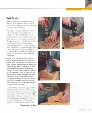
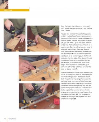
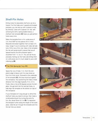
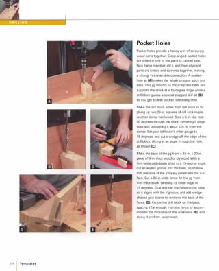
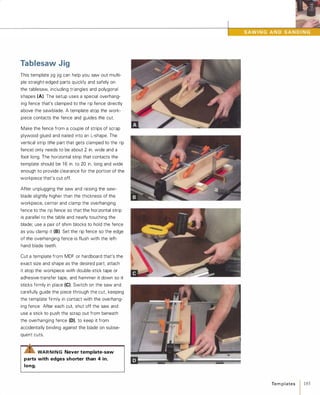
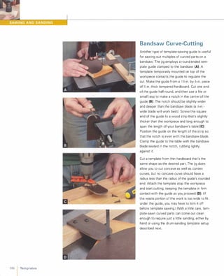
![Drum Sanding
When you want to sand multiple parts a n d keep
them identical, template drum-sanding is the
way to go. If you already have a drum-sanding
dust table for your drill press, a special tool called
a Robosander features a rotating guide bearing
that allows accurate flush sanding to a template
attached to the workpiece (A).
>- See"Drum-SandingDustTable"onp. 255.
Another way to template sand is to mount a disc,
directly below the sanding drum, that contacts
the workpiece template to guide the sanding
process. Use a sanding drum that's slightly
smaller in diameter than the smallest-radius con
cave curve on the workpiece. Cut the disc from
MDF or hardboard that's slightly thinner than the
template you're using.
For pattern sanding rough-cut parts, make the
disc exactly the same diameter as the sanding
drum. However, if you want to use this jig to
finish-sand parts that have been template routed
or sawn, make the guide disc slightly smaller
than the drum-about 1(6 in. or so less in diameter.
Use the circle jig described on p. 1 1 6 to make a
correctly sized disc that's perfectly round (B).Screw the disc to the top of a baseplate that's
large enough to fit to your drill press table. Use a
pair of blocks to help center the disc under the
sanding drum and clamp the baseplate down (e)Lower the sanding drum until it nearly touches
the disc, attach the template to the work, and
you're ready to sand. Press the wood against the
drum lightly at first, working your way around in
several passes (O),until the template is in full
contact with the disc on the final pass.
[TIP] Template sanding is a great way
to clean up the edges of template-sawn
or template-routed parts.
Te m p l ates 1 187](https://image.slidesharecdn.com/077989-130723102817-phpapp01/85/077989-197-320.jpg)
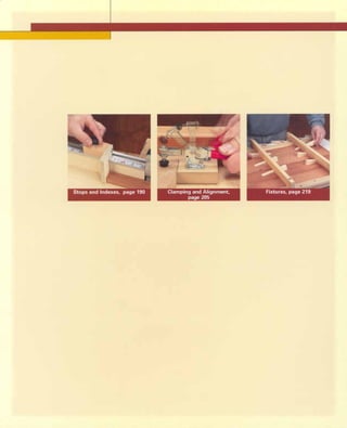

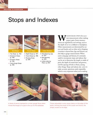
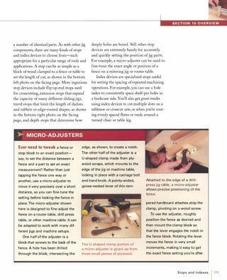
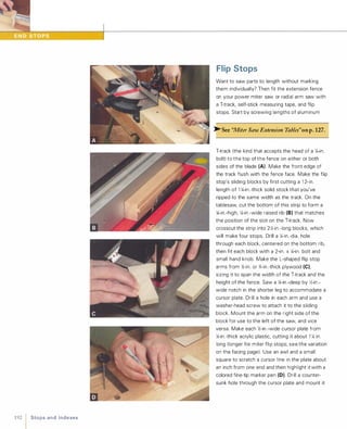
![into the notch on the underside of the flip stop
using a small flat-head screw. With the sliding
stop locked on the track at an exact distance
relative to the blade (say 1 7 in.), attach the stick
on tape measure to the top of the T track so that
the mark for that distance (1 7 in.) is directly
under the cursor (E). Now the flip stop can be
set for accurate crosscuts anywhere along the
track. By flipping the stop up out of the way (F),
you can trim stock ends or cut parts to longer
lengths while saving your stop settings for
reuse later.
[VARIATION] Some parts are too short
to cut to length using a regular flip stop
on an extension fence track. In those
cases, you can screw and glue an exten
sion bar and stop face to a flip stop arm
(without a cursor) (A). The bar should be
long enough to place the flip stop arm in
front of the extension fence; stick the
part of the tape measure left over from
the regular flip stop track (above) and
apply it to the face of the fence. The tape
should be positioned so that the edge of
the stop's arm shows the correct meas
urement. When cutting mitered frame
members, it's often desirable to size
frames by their inside dimensions. To
create a stop for this, mount a triangular
block to the end of a flip stop arm (B),
and fit the arm with a longer cursor that
shows the inside length of the frame
member on the tape measure.
Stops a nd I n dexes 1 193](https://image.slidesharecdn.com/077989-130723102817-phpapp01/85/077989-203-320.jpg)
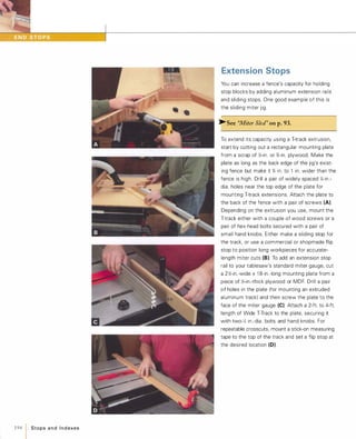
![Eccentric Stops
An easy way to make an end stop with a small
range of fine adjustment is to use the eccentric
cam principal: Drilling an off-center hole in a
round disc or dowel (A) produces a stop that will
shift the position of a part. An eccentric dowel
stop is a good choice for jig setups where you
want to fine-tune the distance between the part
and the cutter, or to readjust the stop to compen
sate for blades/cutters of different thicknesses.
For example, eccentric dowel stops are used on
the pivoting arms of the biscuit slotting table to
adjust the position of slots cut on face frame
stiles. (See p. 1 33.) Eccentric stops are also a
useful addition on a sliding tenoning jig (8),where they allow tweaking of the position of the
shoulder cut. Another style of eccentric stop can
be used to shift the position of a workpiece by
selected intervals. This is useful for drilling several
holes at precise distances from one another, or
to shift a frame member between cuts when
you're chopping a long mortise on a drill press
fitted with a mortising chisel setup. To make a
four-position mortising stop, measure and mark
the desired dimensions on a piece of plywood,
and then trim it to size (e).Mount the stop to
>-See "Four-Sided Base" on p.161.
the mortising fence using a handscrew threaded
into a T-nut (0). Rotating the stop changes the
location of the workpiece relative to the mortis
ing chisel, with each edge of the stop determin
ing a different distance.
[TI P] The farther off-center you drill
the mounting hole on an eccentric stop,
the greater the range of adjustment.
Stops a n d I n d exes 1 195](https://image.slidesharecdn.com/077989-130723102817-phpapp01/85/077989-205-320.jpg)
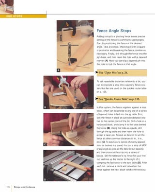
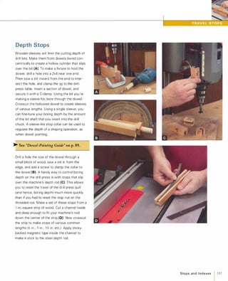
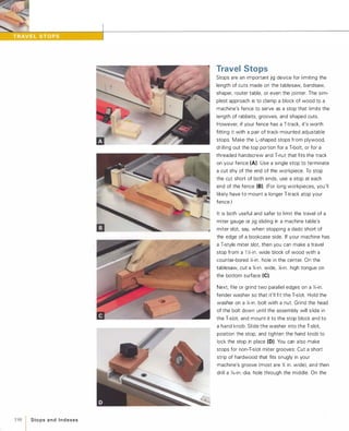
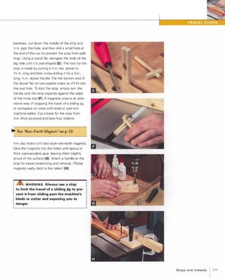
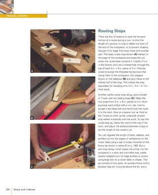
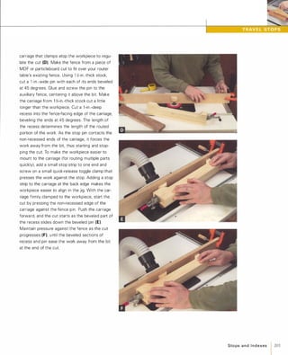
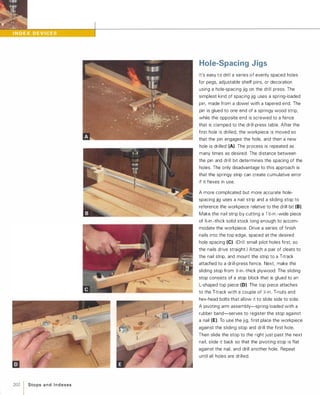
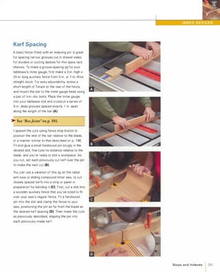
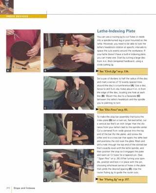
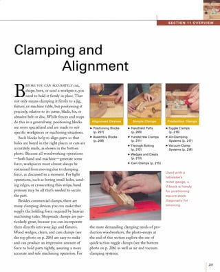
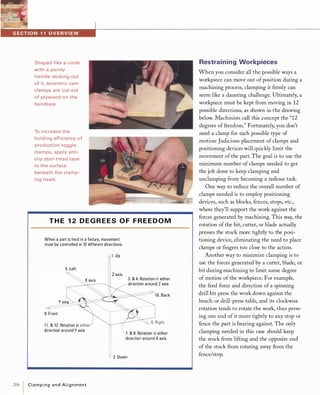
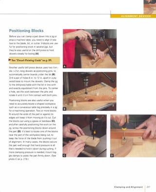
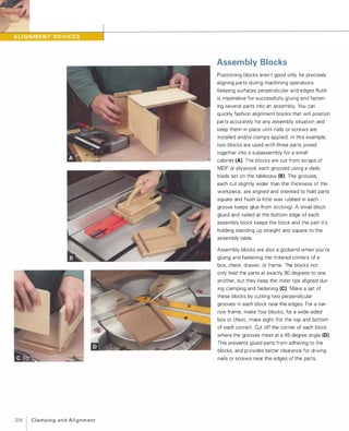
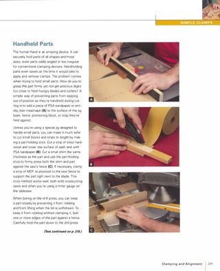
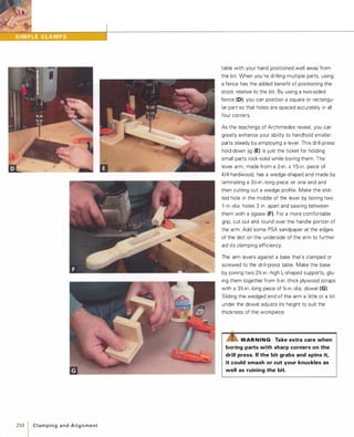
![Handscrew Clamps
Traditional wooden handscrew clamps come in a
wide range of sizes and are great for clamping
stock on a workbench or for securing a fixture to
a machine table. In addition, they're actually
great holding devices by themselves. A hand
screw is terrific for firmly clutching strips, blocks,
or discs too small or awkward to hold by hand.
The surface of the clamp even keeps flat
bottomed parts perpendicular for hole boring (A).
Gripping the large body of the clamp keeps your
hands well away from the bit. Since its jaws
adjust independently, you can use a handscrew
to hold tapered or irregular parts, for example, to
rout grooves or shape edges on a router table (8).Because the clamp is made of wood, there's no
serious harm if the router bit accidentally comes
in contact with the clamp jaws.
You can also use wooden handscrews to hold
small or irregular parts firmly in a jig, fixture, or on
your benchtop. To mount the clamp to a surface,
bore an oversized hole (or rout a slot) perpendicu
larly through each of the clamp's jaws. Fit bolts or
drive long wood screws through these holes (C).
To make a handy holding fixture, cut a 1 0-in. x
1 2-in. baseplate from %-in.-thick MDF, and set a
length of T-track into a groove so it's flush with
the surface.
� See "Extruded T-Tracks" on p.29.
Secure the handscrew to the track with a pair of
T-bolts and hand knobs, and clamp the base into
your bench vise. The clamp firmly holds small
parts for carving, planing, sanding, etc. (0),
while the T-track lets you reposition the clamp
as required.
[TI P] Apair of locking pliers is great for
securely holding tiny parts, screws, etc.,
for sanding, filing or grinding.
C l a m pi n g a n d A l i g n m e nt 1 211](https://image.slidesharecdn.com/077989-130723102817-phpapp01/85/077989-221-320.jpg)
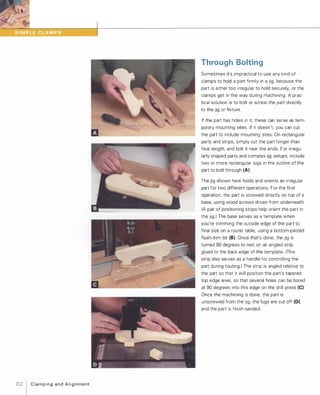
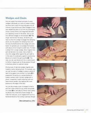
![214 1 C l a m p i n g a n d A l i g n m e n t
lengthwise on the tablesaw, and then sawing out
the angled portion on a bandsaw with its table
tilted (E). Cut another wedge that matches the
angle of the notch. Screw the notched block to
the jig, positioning it over the edge of the part.
(You can also use the block as a stop to hold the
part in the desired position on the jig, thus serv
ing double duty.) To clamp the part down, drive
the loose wedge into the notch. To release parts
from this or any wedge-clamping setup, simply
drive or pull them apart.
Like wedges, cleats are simple devices useful for
securing a part into a fixture, as well as for
attaching a jig to a machine. You can make a
basic cleat from two small scraps of plywood
glued and screwed into an " L " shape. Cut the
short leg of the L as high as the thickness of the
workpiece, and drive a single screw through the
other leg to clamp the part. Basic cleats like
these are very handy for attaching an extension
table or jig table to a machine table (F).Basic
cleats also work well with T-track. Just install a
length of track in the base or other surface of a
fixture or jig, and use T-bolts to secure the cleats
in place (G). The track lets you attach as many
cleats as needed and position them wherever
you wish along length of the workpiece.
[TI P] To make clamping wedges easier
to drive apart, bore a hole into the side
of each wedge, and put the tip of a screw
driver into the hole and tap it with a
mallet.](https://image.slidesharecdn.com/077989-130723102817-phpapp01/85/077989-224-320.jpg)
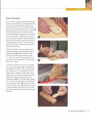
![2161C l a m p i n g a n d A l i g n m e n t
Toggle Clamps
Originally designed for production work, toggle
clamps are extremely useful for holding work
pieces in jigs as well as for clamping jigs to
machines. Also called "quick-action clamps, " tog
gle clamps use a multi-link mechanism to rapidly
engage and disengage a rubber-tipped clamping
head with the flick of a lever (A).
Toggle clamps come in many styles and sizes (B),each designed to suit a specific range of applica
tions. Push-action clamps have a horizontal
plunger that's useful for holding parts against a
fence, stop, or other surface. Lever-action-,
T-handle-, and post-style clamps all have clamping
heads that swing down and press parts flat to a
surface. The differences lie in the way the handle
operates, and its position when locked or
unlocked. Depending on the mounting location,
you might choose a T-handle style over a lever
style model simply because there isn't space
behind the clamp for the lever style's long
locking handle.
Most toggle clamps mount to the surface of a jig
or fixture with four screws (e).You can also
mount a toggle clamp to a T-track by screwing it
to a block and then attaching the block to the
track with a T-bolt (D). When using a toggle
clamp to secure a workpiece in a jig, positioning
it close to the blade or cutter helps keep the part
from moving during machining and also keeps
your hands out of harm's way. Adjust the clamp's
rubber-tipped head to apply enough pressure to
hold the part firmly without making it difficult to
operate the lever. You can improve the clamp's
holding power by adding stair-tread tape or PSA
sandpaper directly under the clamping head.
(See p. 206.)
[TI P] To clamp thicker workpieces,
add a spacer block between a toggle
clamp and the jig.](https://image.slidesharecdn.com/077989-130723102817-phpapp01/85/077989-226-320.jpg)
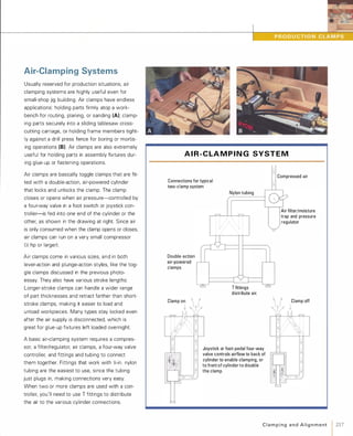
![VAC U U M -C LA M P I N G SYST E M
Foam tape stuck to Atmospheric pressure
fixture base around clamps part down when
perimeter of part
��t tt
air is sucked out.
J�-�
Filter between fixture
and vacuum source
�
.-__���L-________--.
Vacuum valve creates
suction from pressurized air.
:- ...--------{-------------- 1-���
Pressure
regulator
Air supply from compressor
218C l a m p i n g a n d A l i g n m e n t
Air exhaust
Vacuum-Clamp Systems
The pressure exerted by the earth's atmos
phere-1 4 psi-is actually enough to hold parts
securely during many woodworking operations.
All it takes to harness this force is a vacuum. A
vacuum-clamping system supplies and controls
suction between a workpiece and whatever flat
surface it's clamped to-a jig base, a template (A),
a fixture, etc.
You can use a dedicated vacuum pump to gener
ate the suction, but a more compact and eco
nomical alternative is a vacuum valve system as
shown in the drawing at left. This compact
device takes compressed air from a compressor
and passes it through a regulator (set between
40 and 80 psi) and then through a small funnel
like Venturi that generates suction as the air
blows through. A plastic hose connects from the
valve's vacuum port to the clamping surface on
the jig or fixture.
The clamping surface can be made from any non
porous material-plastic, hardboard, melamine,
etc. A thin strip of foam rubber weather-stripping
applied to the clamping surface around the
perimeter of the workpiece forms a gasket that
creates an airtight seal (8).The only condition is
that the part must be at least 1 0 sq. in. in size, as
atmospheric pressure won't hold smaller parts
adequately.
To use this vacuum-clamping setup, turn on the
compressed air and lightly press the workpiece
down on the clamping surface until it's sucked
flat. To prevent large, thin parts from bowing in
the center from the pressure, add strips of
weather-stripping to support the piece in the
middle. Simply turn off the air supply to remove
the part after machining.
[TI P] You can hold many small parts
safely for sanding on a disc or belt sander
by sucking them onto the end of a shop
vacuum hose.](https://image.slidesharecdn.com/077989-130723102817-phpapp01/85/077989-228-320.jpg)
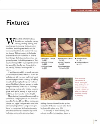
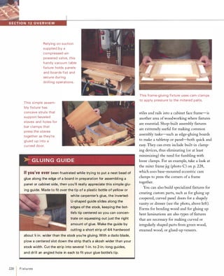
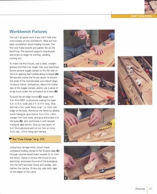
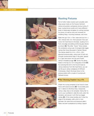
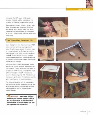
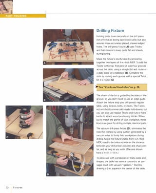
![and then three more rectangles expanding out
wards from the center, each one 1 in. to 2 in.
larger than the preceding one. These lines desig
nate the locations of thin, sticky-backed neoprene
weather-stripping gaskets (E). Before applying
the gaskets, rout out a series of shallow air pas
sages, each spaced between the four gasket
lines. Fit the router with an edge guide, and a
){-in. or %-in.-dia. straight bit (F).
Also rout a %-in.-deep x %-in.-wide groove along
the centerline of the table's length, spanning the
innermost and outermost air channels. This
groove accepts two l -in.-Iong sliding hardwood
blocks, cut to fit the groove snugly (G). With a
short piece of weather-stripping applied across it,
each block acts as a sliding "valve" that directs
the vacuum to a smaller or larger part of the fix
ture, to suit the size and shape of the workpiece.
The square area in the middle of the table pre
vents a loss of vacuum as the bit penetrates the
workpiece.
Somewhere along the length of the innermost air
passage, groove, bore, and tap a hole for the fit
ting that connects the vacuum hose to the table.
� See "Routing Fixtures" onpp.222-223.
Mount the table on a pair of support strips that
are wide enough to provide clearance under the
table for the vacuum hose. (Also add a support
block under the table's center to prevent deflec
tion from bit pressure.) Mount the fixture to your
drill-press table and attach the vacuum valve in a
handy location, for easily engaging and releasing
clamping pressure (H).
[TIP] The gasket-enclosed area on a
vacuum table must be at least 1 0 in. sq.
to generate enough atmospheric clamping
pressure to hold parts securely.
Fixtu res 1 225](https://image.slidesharecdn.com/077989-130723102817-phpapp01/85/077989-235-320.jpg)
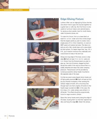
![using #1 0 or #1 2 wood screws. (For larger
clamps, use Y.-in. bolts.) Leave the fasteners
loose enough so the clamp heads can be rotated
with moderate finger pressure.
Now add two or more cross bars that span the
width of the base (E). Attach one end of each bar
to the top of the stop strip, and the other to the
base between clamping heads, where it won't
interfere with clamp adjustment. Fit spacer
blocks under each end of the bars to create a gap
above the base that's � in. wider than the thick
est intended workpiece. Use bolts or long wood
screws to fasten the bars and spacers to the
base. Next, cut a bunch of 4-in. to 6-in.-long
wood wedges to use in conjunction with the
cross bars to keep boards flat during glue-up.
Before actually gluing up a panel, slide the boards
into the fixture, measure the gap left between
the panel and the unlocked clamping heads, and
cut a spacer strip to this dimension. (For really
narrow panels, reposition the clamps on the
base.) Mark the order and orientation of the
boards, and then apply glue to their edges and
set them into the fixture one by one (F). Tighten
the cam clamps slightly and then insert wedges
under the cross bars wherever they're needed, to
keep board edges mated and the assembly flat (G)
Tighten the cam clamps (H) and set the whole
thing aside to dry. After removing the panel from
the fixture, use a plastic scraper or a sponge and
warm water to remove the excess glue from
the base (I).
[TIP] Dry-clamp a panel assembly before
gluing up, to make sure that edges mate
snugly and that the clamping process will
proceed smoothly.
Fixtu res 1227](https://image.slidesharecdn.com/077989-130723102817-phpapp01/85/077989-237-320.jpg)
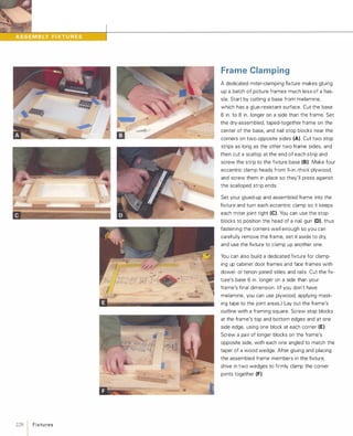
![Coopered Panel Fixture
Curved wood doors can make an otherwise
plain-looking cabinet a lot more interesting. A
coopered panel fixture makes it a lot easier to
glue up a series of beveled staves into a perfect
curved door, lid, or panel.
Start by calculating the number of staves you'll
need for your panel, along with their width and
bevel angle. The desired radius of the panel's
face determines the radius of the concave form.
Cut the forms from 3/4-in.-thick stock, making
them at least 6 in. wide and an inch or two longer
than the panel's width. Make enough forms to
support the panel at least every 8 in. to 12 in. Cut
the forms with a jigsaw or an arc-sawing jig (A).
� See "Arc-Sawing" onp.118.
Drill two holes in each form large enough to
accommodate the head of a bar clamp (8).
Locate the holes on either side of the form's cen
terline, no more than an inch or so below the
curved edge. Cut two 4-in. to 6-in.-wide sides for
the fixture from %-in.-thick stock, and mark for
proper spacing of the forms. Temporarily clamp
the sides to the forms, and then screw or nail
each one in place (e).To prevent the glued-up
panel assembly from sticking, cover each form
edge with masking tape (0).
After doing a dry-assembly to ensure that every
thing will clamp up smoothly, place the glued-up
staves in the form and set a couple of scrap
strips against the panel's outer edges. Set all the
clamps into place first, and then tighten each
opposing pair a little at a time, making sure the
stave's edges stay aligned and the panel stays
straight on the form (E).
[TI P] It's easier to scrape glue drips
from a coopered door assembly when the
glue is still rubbery than to wait until it's
rock-hard.
Fixtu res 1 229](https://image.slidesharecdn.com/077989-130723102817-phpapp01/85/077989-239-320.jpg)
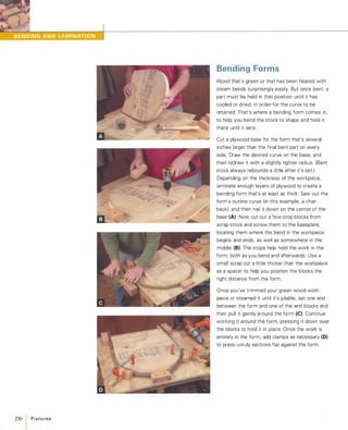
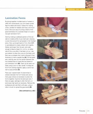
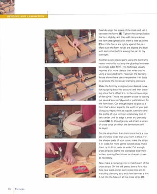
![Using a small square as a guide, position the
cross strips and glue and nail them to the form,
with the T-nuts facing down (I). Now put a y,;-in.
bolt and washer through the holes in each of the
clamping strips.
Do a dry-assembly, clamping your veneers to the
form to see that everything fits together correctly.
After removing all the clamping strips, apply glue
to the veneers and tape the ends of the lamina
tion together to help keep them aligned.
Sandwich the bundle between two strips of )i-in.
thick plywood or hardboard to help distribute the
clamping pressure of the strips. Set the end of
the bundle under a couple of clamping strips at
the more tightly curved end of your form (if there
is one) (J), and tighten these strips down. As you
pull the lamination bundle down over the form,
add clamping strips to every other cross strip (K),tightening them only partially. When the bundle is
fully bent, add the remaining clamping strips and
tighten all of them, using a socket driver in a
cordless drill IL).The drill allows you to tighten or
loosen the clamping strip bolts much more quickly
than you could hand-tighten bar clamps. The
drill's clutch also lets you tighten all the bolts to
uniform tightness, better ensuring an evenly and
cleanly clamped final workpiece.
[TI P] For laminated parts that must
conform to an exact curve, it's crucial to
glue up a test part first to assess the
amount of spring-back after the assembly
has dried.
•
Fixtu res 1 233](https://image.slidesharecdn.com/077989-130723102817-phpapp01/85/077989-243-320.jpg)
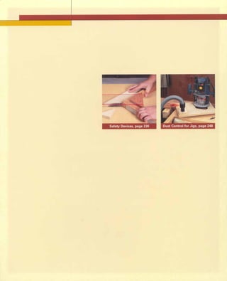

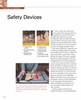
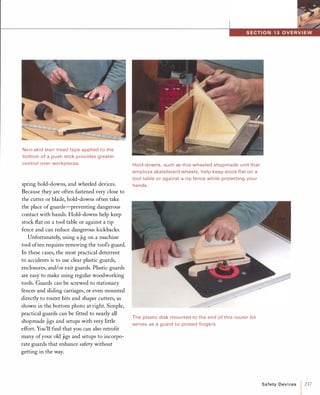
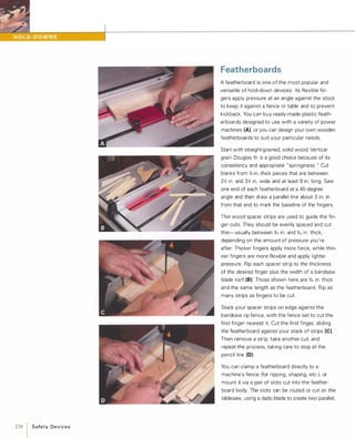
![stopped cuts (E). The slotted holes make it easy
to properly locate the featherboard and to set the
amount of pressure it applies to the stock.
To mount a wood featherboard flat on a machine
table, you can make the featherboard long
enough to clamp at the table's edge, or you can
attach it with magnets. Alternatively, you can
screw it to a scrap of wood that clamps to the
table, or use T-slot fasteners to attach it directly
to T-slot-style miter slots. One flexible approach
involves clamping a wood strip into your
machine's miter gauge slot and then attaching a
featherboard to the strip (F).For certain cuts, featherboards are often used in
pairs. A featherboard or spring hold-down mounted
on the fence keeps stock flat on the machine
table, while another mounted on the machine
table keeps the stock firmly riding against the
fence (G). This works wel l when you're cutting
straight-edged strips and parts of all sizes.
Usually, it's best to press the featherboard against
the stock near the point of the cut. When the
workpiece has a curved or irregular edge, use a
pair of featherboards, with one pressed freehand
(H) against the irregular side of the work.
[TIP] To mount a featherboard to an
iron or steel table/fence quickly and easily,
try inlaying two or more rare-earth
magnets into its body, using epoxy or
cyanoacrylate glue.
"Z!S"WAR N I N G Never position a
featherboard to press stock directly
against the side of a blade or cutter
because it can pinch the stock, causing
kickback.
Safety Devices 1 239](https://image.slidesharecdn.com/077989-130723102817-phpapp01/85/077989-249-320.jpg)
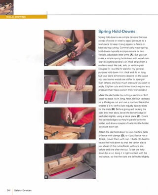
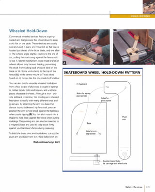
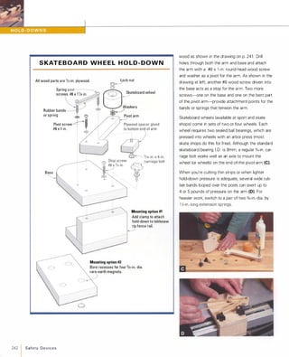
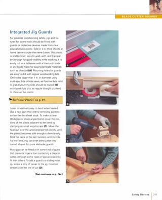
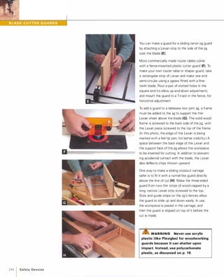
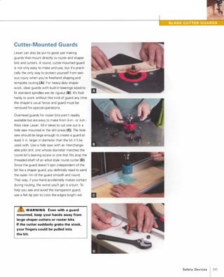
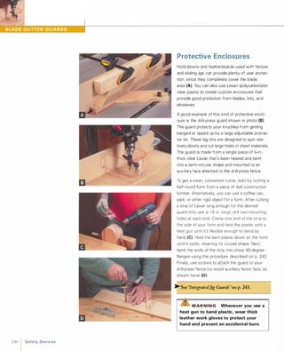
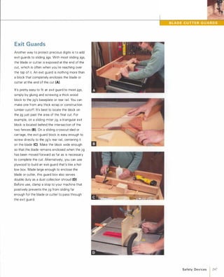
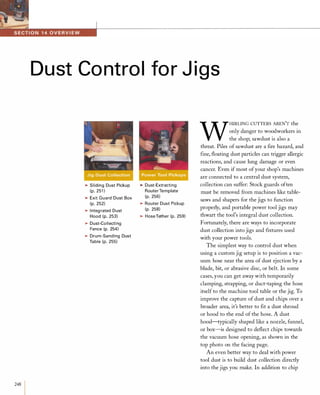
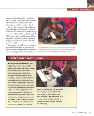
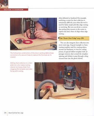
![Sliding Dust Pickup
Because most crosscut sleds, miter-cutting jigs,
tenon-cutting jigs, and other tablesaw jigs pass
directly over the blade, the saw's stock blade
guard must usually be removed. In these cases,
it's best to incorporate a custom-made blade
guard into the jig itself. Better yet, you can build
dust collection into your custom guard by incor
porating an overhead dust pickup.
Adding a dust pickup to a jig such as the miter
sled shown (A) is easy. First strengthen the thin
plastic guard to support a vacuum hose port. Add
a �-in. by �-in. wood strip to each edge of the
plastic (8). You can either cut a groove along the
length of each strip to capture the edge of the
plastic, or cut a rabbet on the strip and screw it
to the guard (e).The easiest way to attach a
vacuum hose is to add a ready-made hose port
(available from woodworking supply catalogs),
which attaches over a 2X-in.-dia. hole bored
through the guard. It is fastened with four small
machine screws and washers (D). Locate the
port near the middle of the guard to capture
debris thrown upward by the blade.
To add dust collection to a tablesaw tenon jig,
bore a hole through the jig's guard (E) to provide
a snug mount for a small vacuum hose. Use a cir
cle cutter, hole saw, or Forstner bit chucked in
the drill press to bore the hole near the rearmost
section of the guard. To keep the hose from inter
fering with the sliding jig during use, secure the
hose to the jig with a plastic pipe strap, locking
tie, or twist tie.
[TIP] Dust collection works best when
chips are evacuated in the same direction
they're thrown by the cutter. Observe the
travel of debris to best locate the dust port.
D u st Control fo r J i g s 1 251](https://image.slidesharecdn.com/077989-130723102817-phpapp01/85/077989-261-320.jpg)
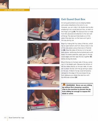
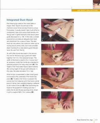
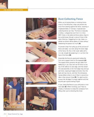
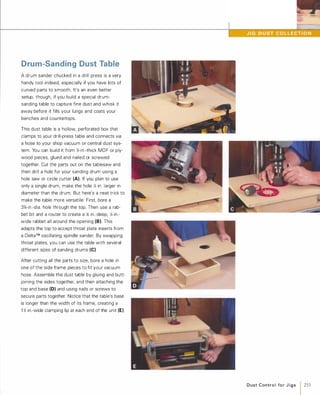
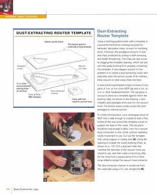
![Set the router's depth of cut to leave at least
X; in. of thickness around the template opening to
support the guide bushing. Rout at least % in.
back from the template's opening all the way
around, and then rout a wide passage leading to
the dust port hole.
Flip the template right-side up and glue and nail
the vacuum collar in place over the port hole (e).Next, bore a row of Y.;-in.-dia. holes all the way
around the template opening (0). These air-inlet
holes keep the shop vac from straining and help
collect dust from the top of the template, keep
ing it cleaner.
Make the bottom from a piece of thin hardboard
the same width and length as the top. Align the
two pieces, trace the template opening onto the
bottom piece, and then cut it out with a jigsaw.
Nail the bottom to the underside of the top
after applying a liberal coat of glue to seal the
connection (E).
In preparation for routing, the dust-extracting tem
plate is firmly clamped atop the workpiece (F),and the vacuum hose is pushed into the port. Fit
your router with the guide bushing and straight
bit appropriate to the template's offset and you're
ready to rout (G).
� See "Calculating Template Offset" on p.170.
[TI P] To prevent a dust-extracting tem
plate from slipping out of position during
routing, apply a few strips of fine-grit
PSA-backed sandpaper to the underside
of the jig before clamping it down.
m � --=
D u st Control fo r J i g s 1257](https://image.slidesharecdn.com/077989-130723102817-phpapp01/85/077989-267-320.jpg)
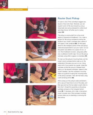
![Hose Tether
Many newer-model circular saws, sanders,
routers, and other portable power tools have
integral dust collection ports for connection to a
shop vac hose. Unfortunately, an attached hose
can make a power tool feel terribly unwieldy. A
tether attached to your bench or work counter
can help keep a hose out of your way.
You can tack together a hose tether in minutes
from a couple of pieces of 1 x2 stock. Cut a post
36 in. to 42 in. long, and nail a 1 2-in.-long arm to
one end. Reinforce the joint by gluing and nailing
on a couple of gussets cut from thin plywood
scrap (A). Install a screw eye near the end of the
arm to hold a short bungee cord that will support
your power tool's hose (8). If the tether will be
held in a bench vise, nail on a cleat a few inches
from the end to make the post sit more securely.
If you dedicate a vacuum hose to a single power
tool, attach the tool's electrical cord to the hose
with duct tape or wire or plastic ties (e).Attaching
the two together makes either less likely to snag
or hang up as you work. Loop the bungee cord
around the hose and cord and attach it securely
to the screw eye so it won't spring back suddenly
and cause injury. Be sure to leave enough slack in
the hose to allow it to reach to the end of a long
board you might be working on (0).
[TI P] If your shop has low, open rafters,
you can simply attach a bungee cord to
a rafter above your bench to hang a
portable power tool's cord and hose.
D u st C o ntrol for J i g s 1 259](https://image.slidesharecdn.com/077989-130723102817-phpapp01/85/077989-269-320.jpg)

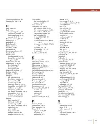
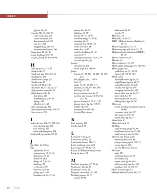


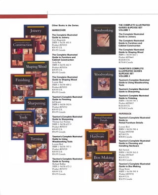


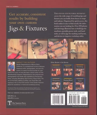

This document provides an overview of stops and indexes that are commonly used in jigs and fixtures to control measurements and repeat operations accurately. It discusses how stops can be used to set lengths, depths, distances and positions. Indexing devices are specifically useful for consistently spacing repeated holes, cuts or shapes. The document provides examples of different types of stops and indexes and how they can aid in marking, cutting and routing operations.