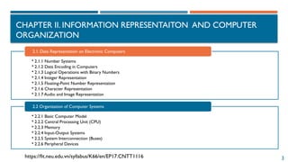
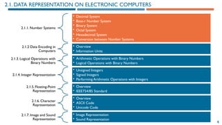
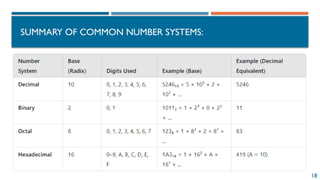
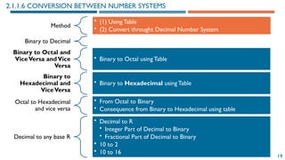
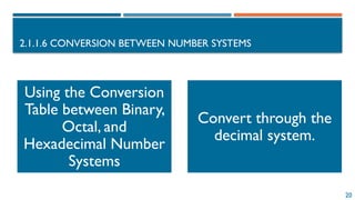
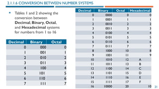
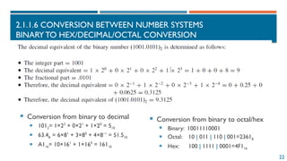
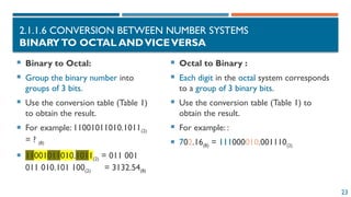
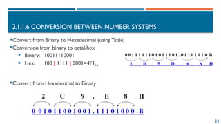
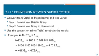
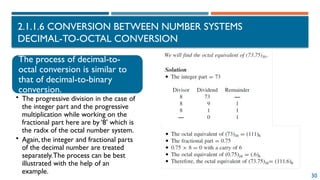
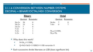
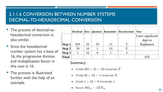
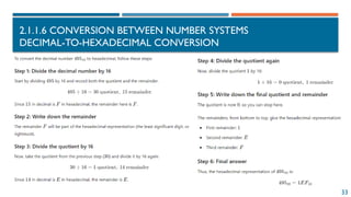
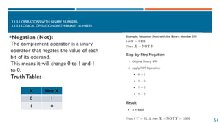
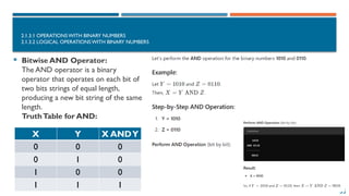
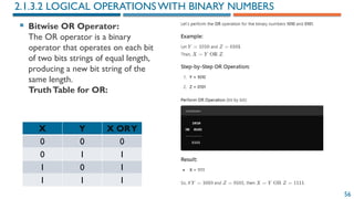
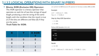
The document provides an introduction to information representation and computer organization, covering various number systems including decimal, binary, octal, and hexadecimal. It explains data encoding in computers, logical operations with binary numbers, and various representations such as integers, floating-point numbers, and characters. Additionally, it discusses the organization of computer systems, including central processing units, memory, and input-output systems.


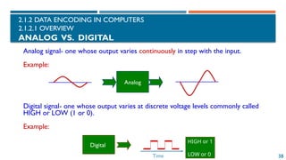
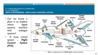
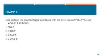
![62
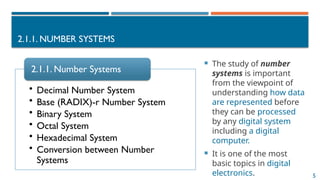
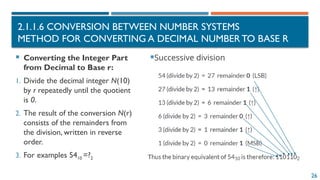
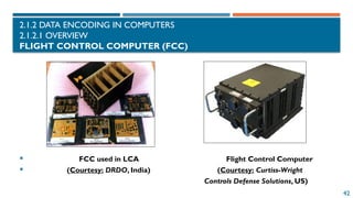
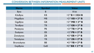
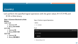
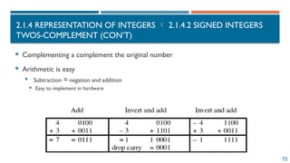
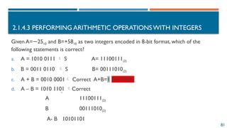
2.1.4 REPRESENTATION OF INTEGERS
2.1.4.1 UNSIGNED INTEGERS
Represent the following unsigned integers using
8 bits:
A = 45 B = 156
A = 45 = 32 + 8 + 4 + 1 = 25
+ 23
+ 22
+ 20
→ A = 0010 1101(2)
B = 156 = 128 + 16 + 8 + 4 = 27
+ 24
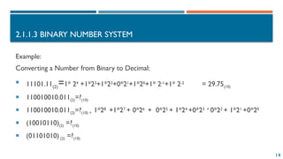
+ 23
+ 22
→ B = 1001 1100(2)
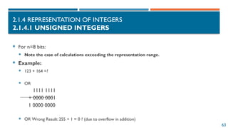
• For n = 8 bits:
• The range of representation is
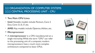
[0,255]
0000 0000 = 0
0000 0001 = 1
0000 0010 = 2
0000 0011 = 3
.....
1111 1111 = 255](https://image.slidesharecdn.com/02chapter2datarepresentationandorganizationofcomputersystemv42-241222052605-a53f82f8/85/02-Chapter-2-Data-representation-and-organization-of-computer-system_V4-2-pptx-62-320.jpg)
![67
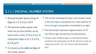
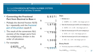
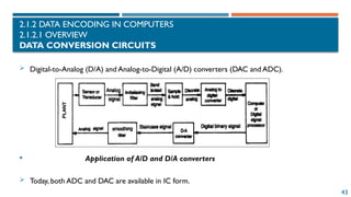
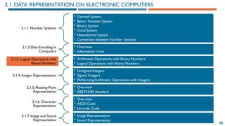
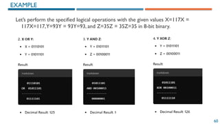
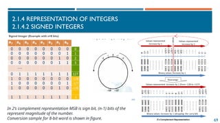
2.1.4 REPRESENTATION OF INTEGERS
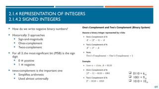
2.1.4.2 SIGNED INTEGERS
[-2n-1
, 2n-1
-1]
an-1an-2 ….a2a1a0](https://image.slidesharecdn.com/02chapter2datarepresentationandorganizationofcomputersystemv42-241222052605-a53f82f8/85/02-Chapter-2-Data-representation-and-organization-of-computer-system_V4-2-pptx-67-320.jpg)

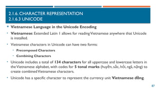
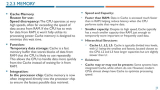
![83
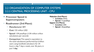
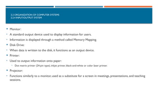
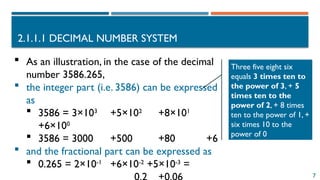
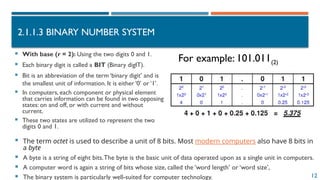
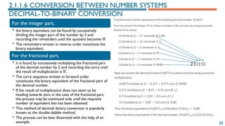
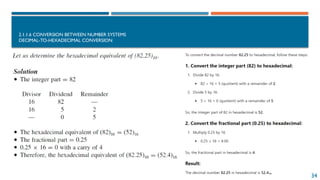
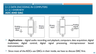
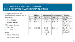
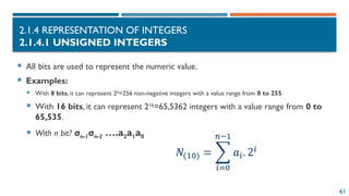
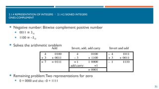
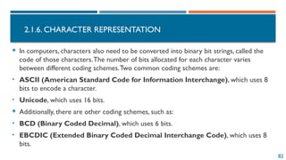
AMERICAN STANDARD CODE FOR
INFORMATION INTERCHANGE
Hexa-decimal 0 1 2 3 4 5 6 7
0 <NUL>
0
<DEL>
16
<SP>
32
0
48
@
63
P
80
`
96
p
112
1 <SOH>
1
<DC1>
17
!
33
1
49
A
65
Q
81
a
97
q
113
2 <STX>
2
<DC2>
18 34
2
50
B
66
R
82
b
98
r
114
3 <ETX>
3
<DC3>
19
#
35
3
51
C
67
S
83
c
99
s
115
4 <EOT>
4
<DC4>
20
$
36
4
52
D
68
T
84
d
100
t
116
5 <ENQ>
5
<NAK>
21
%
37
5
53
E
69
U
85
e
101
u
117
6 <ACK>
6
<SYN>
22
&
38
6
54
F
70
V
86
f
102
v
118
7 <BEL>
7
<EBT>
23
‘
39
7
55
G
71
W
87
g
103
w
119
8 <BS>
8
<CAN>
24
(
40
8
56
H
72
X
88
h
104
x
120
9 <HT>
9
<EM>
25
)
41
9
57
I
73
Y
89
i
105
y
121
A <NL>
10
<SUB>
26
*
42
:
58
J
74
Z
90
j
106
z
122
B <VT>
11
<ESC>
27
+
43
;
59
K
75
[
91
k
107
{
123
C <FF>
12
<FS>
28
,
44
<
60
L
76
92
l
108
|
124
D <CR>
13
<GS>
29
-
45
=
61
M
77
]
93
m
109
}
125
E <SO>
14
<RS>
30
.
46
>
62
N
78
^
94
n
110
~
126
F <SI>
15
<US>
31
/
47
?
63
O
79
-
95
o
111
<DEL>
127](https://image.slidesharecdn.com/02chapter2datarepresentationandorganizationofcomputersystemv42-241222052605-a53f82f8/85/02-Chapter-2-Data-representation-and-organization-of-computer-system_V4-2-pptx-83-320.jpg)