
Recommended
More Related Content
What's hot
What's hot (20)
Similar to unit 6 pumps and primers.pptx
Similar to unit 6 pumps and primers.pptx (20)
Recently uploaded
Recently uploaded (20)
unit 6 pumps and primers.pptx
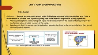
- 1. UNIT 6: PUMP & PUMP OPERATIONS Introduction Definition: Pumps are machines which make fluids flow from one place to another. e.g. From a foam tender to the fire. The hydraulic pump has two functions to perform during operation: i. Allowing atmospheric pressure to push liquid into the inlet line from the reservoir to the pump by the mechanical action created vacuum at the pump. ii. It performs is that the pumps mechanical action supplies the liquid to the pump outlet and then forced into the hydraulic system.
- 3. 7.2 Classification of common types pumps in use Pumps are mainly classified into three categories i. Positive displacement pumps ii. Negative displacement pumps (centrifugal pumps) iii. Ejector pumps
- 4. Positive Displacement Pumps Positive Displacement Pumps are the Non-centrifugal pumps used by the Fire Service. These usually have a reciprocating piston which makes an air- and liquid-tight seal with the cylinder in which it moves Meaning: A positive displacement pump is one in which a definite volume of liquid is delivered for each cycle of pump operation. This volume is constant regardless of the resistance to flow On the upward stroke of the piston a reduced pressure is created in the cylinder causing the inlet valve (A) to open and the outlet valve (B) to close, so that air or water is drawn into the cylinder through the inlet valve. On the downward stroke the inlet valve closes and the contents of the cylinder are forced, under positive pressure, through the outlet valve.
- 5. --Positive displacement pumps are used in a range of applications from services where a specific amount of liquid is required to be moved into a system to heavier duty services where the liquid is simply to viscous to be handled by a centrifugal pump --Positive displacement pumps operate with a series of working cycles. Each cycle encloses a certain volume of fluid and moves it mechanically through the pump into the system. While the maximum pressure developed is only limited by the mechanical strength of the pump and system and the driving power available, the effect of that pressure can be controlled by a pressure relief or safety valve. --A major advantage of the positive displacement pump is its ability to deliver consistent capacities because the output is solely dependent on the basic design of the pump and the speed of its driving mechanism. Application of Positive displacement pumps
- 6. Positive displacement pumps . Hand pumps Power driven pump Single acting hand pump Stirrup pump Force Pumps Lift pumps Bucket and plunger pumps Rotary pumps
- 7. Positive displacement pumps –Hand pumps Hand pumps are manually operated pumps; they use human power and mechanical advantage to move fluids or air from one place to another. They are widely used in every country in the world for a variety of industrial, marine, and irrigation activities. There are many different types of hand pump available, mainly operating on a piston, diaphragm or rotary vane principle with a check valve on the entry and exit ports to the chamber operating in opposing directions. Most hand pumps have plungers or reciprocating pistons, and are positive displacement
- 8. Single Acting Hand Pumps: Water hand pumps are manually operated pumps; they are used for bringing water from earth underground to earth surface and is used in every country for a variety of industrial, marine, irrigation and household purposes. Image shown below is the typical design of Hand Pump.
- 9. Up-Stroke: During the upstroke the piston valve is closed. Water that is in the upper cylinder is under positive pressure and is pushed upward into the riser main. A negative pressure is created in the lower cylinder. This negative pressure causes the foot valve open and water is pulled into and fills the lower cylinder. Down-Stroke: As the piston assembly moves downward, pressure increases in the lower cylinder and the foot valve closes. Increasing pressure in the lower cylinder also pushes the piston valve open and water flows upward and fills the upper cylinder. As the up-stroke is repeated, water is again pushed upward through the riser main. This process is repeated over and over again as the pump handle is operated. Principle of Hand Pump: The majority of pumps used in developing nations are “displacement pumps”. Because water cannot be compressed, it can be pushed or “displaced”. The most commonly used displacement pumps are also referred to as piston pumps because they utilize a piston sealed within a cylinder to displace water upwards out of the well.
- 10. Stirrup Pumps: Stirrup Pump is a hand-operated vertical reciprocating pump in which the base of the cylinder is placed in a bucket of water. Meaning: Stirrup Pump is a portable hand-operated water pump with a footrest resembling a stirrup (footrest), used to extinguish small fires. Stirrup Pump can be used to extinguish small fires using the minimum quantity of water and they are operating on the bucket and plunger principle. As there are only three moving parts wear and tear is comparatively low. The moving parts are:- i. The plunger rod ii. A ball valve which, forms the foot valve iii. A ball valve which, forms a non-return valve in the piston at the base of the plunger rod.
- 11. Principle of Stirrup Pump: -There is an outlet at the top of the pump. This outlet is connected to a long rubber tubing of 12.5mm nozzle . A stirrup is attached to the pump and when not in use the hose is coiled and secured by a strap. When the pump is to be operated the hose is uncoiled and the pump casing is placed in a water container with the stirrup on the ground. The operator holds the pump in correct position by placing his foot on the stirrup. When the plunger rod and the piston move upwards the foot valve opens . Simultaneously the ball valve in the piston closes and any water above the piston flows out through the discharge pipe. On the downwards stroke, the foot valve closes, the ball valve in the piston opens and a certain fixed quantity of water enters the upper part. Part of water is forced in to the discharge pipe, the amount being equal to the displacement caused by the plunger rod.
- 12. Advantages of Stirrup Pumps i. They are light in weight and easily portable. The operator has to carry only a light nozzle. ii. They can be employed with considerable speed. iii. The jet of 7 metres can be maintained. The jet can be turned ON or OFF. iv. Initial cost is low as they are simple in construction. v. Easy to operate and their chances of breakdown is very less. vi. The person pumping is clear of pollution ( heat and smoke).
- 13. Crews of three generally operate these pumps. One man carries the nozzle and attacks the fire while the other two remain with the pump. One does the pumping and the other feeds the pump with water. These two can exchange duties as the man on the pump becomes tired. Disadvantages of Stirrup Pumps i. Two or three persons are needed to operate them. ii. Sufficient supply of water in containers must be available or arrangement must be made to carry a portable supply. iii. Considerable physical exertion is needed for pumping for a long period.
- 14. Positive displacement pumps – Power Driven Pumps Power pumps convert rotary motion to low speed reciprocating motion by a crankshaft, connecting rods and crossheads bearing. Plungers or pistons are driven by the crosshead drives. Power pumps typically have high efficiency and are capable of developing very high pressures. They can be driven by electric motors. They are relatively expensive pumps and can rarely be justified on the basis of efficiency over centrifugal pumps. In general, the effective flow rate of reciprocating pumps decreases as the viscosity of the fluid being pumped increases because the speed of the pump must be reduced. In contrast to centrifugal pumps, the differential pressure generated by reciprocating pumps is independent of fluid density. It is dependent entirely on the amount of force exerted on the piston.
- 15. There are four main types of Positive displacement pumps – Power Driven Pumps within this category: i. Force Pumps ii. Lift pumps iii. Bucket and plunger pumps iv. Rotary pumps All these types have a plunger or rotor, which makes an air and water- tight joint with the pump casing. Displacement between the moving parts and the casing imparts energy to the fluid,. These pumps can be used to pump both liquid and gas.
- 16. Force Pumps - Single Acting Force Pump The force pump is the simplest type of pump. It consists of a solid piston or plunger, which moves within a cylinder fitted with inlet and outlet valve. It takes fluid on the up stroke and forces it out on the down stroke.
- 17. During the section stroke when the piston moves upwards, the inlet valve opens and the outlet valve is then closed. During delivery stroke the piston is pushed downwards. On account of the force created below the piston, the outlet valve opens and the inlet valve closes. This type of pump is known as single acting pump. To provide a more continuous flow in a single acting pump, an air vessel may be connected on the delivery side of the pump. The air vessel is an airtight chamber with a capacity of not less than six times than the pump.
- 18. Force Pumps - Double Acting Force Pump They are introduced to reduce the pulsating effect and offer a continuous discharge. If the water acts on only one side of the piston it is known as single acting and if it acts on both sides of piston is known as ‘Double Acting Force Pumps’. This type has one inlet and outlet valve each placed on both sides of the piston. The operation of ‘Double Acting Force Pumps’ is similar to that single acting pump but pumping takes place on both sides of piston. This pump is more efficient that a single-acting force pump. Each stroke of the piston fills one chamber and empties another, which nearly doubles the flow rate over a single-acting force pump.
- 19. Lift Pumps The lift pump is similar to the force pump, but it has a hollow plunger with a valve, which permits fluid to pass freely only in one direction. On the first stroke, as the plunger moves upward, the inlet valve opens and a quantity of water is drawn into the cylinder. The plunger valve remains closed. On the second stroke, as the plunger moves downwards the inlet valve closes and the plunger valve opens. Water passes through the plunger into the upper portion of the cylinder. When the plunger rises again on the next stroke, the water cannot return as the valve is closed. It is consequently expelled through the outlet and more water is drawn in through the inlet valve
- 20. Bucket and Plunger Pumps They are a combination of force and lift pumps. They operate in a similar way to the lift pump. Instead of connecting to a single plunger rod a column or trunk is mounted onto the plunger. When the Plunger rises it draws in fluid through the inlet valve. At the same time the fluid which has been wrapped in the upper part of the cylinder by the closure of the plunger valve is forced through the outlet. When the plunger descends, its valve opens again and fluid is forced out by the displacement action of the trunk. This process ensures a continuous flow from the pump even though it is not double acting. All the above three pumps are grouped under the category called reciprocating fire pumps
- 21. Rotary Gear Pumps Definition of gear pump: Gear pumps are positive displacement rotary pumps that transport liquids using rotating gears. They function through the use of two or more gears that create vacuum pressure, propelling the fluid media. Gear pumps are compact, high pressure pumps which provide a steady fluid flow. There are several variations of gear pumps.
- 22. The simple gear pump shown in Figure consists of two spur gears meshing together and revolving in opposite directions within a casing. Only a few mm clearances exist between the case and the gear faces and teeth . When the gear teeth mesh with the teeth of the other gear, the space between the teeth is reduced, and the entrapped liquid is forced out the pump discharge pipe. As the gears revolve and the teeth disengage, the space again opens on the suction side of the pump, trapping new quantities of liquid and carrying it around the pump case to the discharge. As liquid is carried away from the suction side, a lower pressure is created, which draws liquid in through the suction line. With the large number of teeth usually employed on the gears, the discharge is relatively smooth and continuous, with small quantities of liquid being delivered to the discharge line in rapid succession. If designed with fewer teeth, the space between the teeth is greater and the capacity increases for a given speed; however, the tendency toward a pulsating discharge increases. In all simple gear pumps, power is applied to the shaft of one of the gears, which transmits power to the driven gear through their meshing teeth.
- 23. Operation: Gear pump uses two identical gears rotating against each other-one gear is driven by a motor and it in turn drives the other gear. Each gear is supported by a shaft with bearings on both sides of the gear. i. As the gears come out of mesh, they create expanding volume on the inlet side of the pump. Liquid flows into the cavity and is trapped by the gear teeth as they rotate. ii. Liquid travels around the interior of the casing in the pockets between the teeth and the casing -- it does not pass between the gears. iii. Finally, the meshing of the gears forces liquid through the outlet port under pressure. Because the gears are supported on both sides, gear pumps are quiet- running and are routinely used for high-pressure applications such as hydraulic applications i.e. to supply water to hose reels
- 24. Positive Displacement Pump Protection Positive displacement pumps are normally fitted with relief valves on the upstream side of their discharge valves to protect the pump and its discharge piping from over pressurization. Positive displacement pumps will discharge at the pressure required by the system they are supplying. The relief valve prevents system and pump damage, if the pump discharge valve is shut during pump operation or if any other occurrence such as a clogged strainer blocks system flow.
- 25. Negative Displacement Pump - Centrifugal Pumps Definition: A pump in which water is moved by the spinning action of an impeller. A centrifugal pump consists essentially of a spinning circular metal casting with radial vanes, called the impeller (Refer Figure), enclosed in a casing. Water at the centre of the impeller is thrown outwards by centrifugal force as the impeller rotates and discharged through vanes thereby causing a partial vacuum to be created at the centre. This causes more water to be forced into the impeller from the supply source so that flow from the centre of the impeller to its periphery is continuous.
- 26. Operating Parts of Centrifugal Pumps: Centrifugal pumps basically consist of a stationary pump casing and an impeller mounted on a rotating shaft. The pump casing provides a pressure. boundary for the pump and contains channels to properly direct the suction and discharge flow. The pump casing has suction and discharge penetrations for the main flow path of the pump and normally has small drain and vent fittings to remove gases trapped in the pump casing or to drain the pump casing for maintenance. Figure above is a simplified diagram of a typical centrifugal pump that shows the relative locations of the pump suction, impeller, volute, and discharge. Impeller Casing: Volute: Guide vanes / Diffuser:
- 27. Casing: Casing is the chamber surrounding the impeller in a centrifugal pump. The action of the impeller in pulling water outwards causes considerable turbulence and friction. These factors lead to waste of energy. The casing is designed in order to reduce the wasting of energy. It brings down the velocity of the water and imparts a steady and smooth flow and thus reduces the wasting of energy. The casing may take the form of a volute and / or guide vanes. Volute: Volute is a type of casing in a centrifugal pump, shaped like the shell of a snail, where kinetic energy is converted to pressure energy. The volute is a region that expands in crosssectional area as it wraps around the pump . The purpose of the volute is to collect the liquid discharged through the vanes of the impeller at high velocity and gradually cause a reduction in fluid velocity by increasing the flow area. This converts the velocity head to static pressure. The fluid is then discharged from the pump through the discharge connection.
- 28. Guide vanes / Diffuser: Guide vanes is radial shape structure in impeller to guide water to be discharged are attached to the inner walls of the impeller which can also reduce turbulence. They are sometimes collectively known as a guide ring or diffuser. Guide ring or diffuser is a ring or set of stationary guide vanes that surround the impeller in the casing of a centrifugal pump designed to reduce turbulence. Some centrifugal pumps contain diffusers. The purpose of the diffuser is to increase the efficiency of the centrifugal pump by allowing a more gradual expansion and less turbulent area for the liquid to reduce in velocity. The diffuser vanes are designed in a manner that the liquid exiting the impeller will encounter an ever increasing flow area as it passes through the diffuser. This increase in flow area causes a reduction in flow velocity, converting kinetic energy into flow pressure. However, their efficiency is greater than that of the simple volute.
- 29. Multi-Stage Centrifugal Pumps Single-stage pump: A centrifugal pump with one impeller. Multi-stage pump: A centrifugal pump with two or more impellers. Pumps with a single impeller, as described above, are capable of developing pressures of anything up to about 20 bars, depending on the particular design and the flow rate required. If higher pressures are required, for the operation of high pressure hose reels for example, there are two methods by which they might be achieved with a single impeller of this type: i. by increasing the speed of the impeller; ii. by increasing its diameter. Increasing the speed of the impeller can only be achieved by increasing the speed of the engine and it may be neither practicable nor desirable to do this. Increasing the diameter is comparatively inefficient and would make the pump more bulky. Hence, to achieve a high outlet pressure,
- 30. it is better to use a multi-stage pump, i.e. a pump with two or more impellers in series. A more economical approach to developing high pressures with a single centrifugal pump is to include multiple impellers on a common shaft within the same pump casing. Internal channels in the pump casing route the discharge of one impeller to the suction of another impeller; so that, neglecting friction losses, the pressure increasing ability of the centrifugal pump is applied a number of times. Multi-stage pump centrifugal pump Several stages are required to achieve the high pressures needed for hose reel operation and, although pumps of this type are in use, most fire service pumps consist of only two stages Practically multi-stage pumps have the important advantage that water may be discharged at relatively low pressure after passing through the first stage only, or at high pressure (up to about 55 bars) after passing through subsequent stages.
- 31. A pump stage is defined as that portion of a centrifugal pump consisting of one impeller and its associated components. Most centrifugal pumps are single-stage pumps, containing only one impeller. A pump containing seven impellers within a single casing would be referred to as a seven-stage pump or, or generally, as a multi-stage pump.
- 32. Characteristics of Centrifugal Pumps i. At any given speed of the pump, when there is no flow, the pressure is at a maximum (closed valve pressure) ii. The pressure decreases as the delivery valves are gradually opened and the flow increases. iii. When the pump speed increases both flow and pressure increases. iv. When suction lifts increases both flow and pressure decreases. v. The output of the pump will be decreased, if length of the suction hose is increased and vice versa.
- 33. Advantages of Centrifugal Pumps i. They can be operated in high rotation to achieve maximum discharge. ii. Pump will function even though the delivery valve is shut and there is no adverse effect on the engine. iii. They have a continuous flow of water. iv. They are simple in construction. v. As there are only few moving parts, wear and tear is less. vi. They occupy less space. Disadvantages of centrifugal Pumps As they are not self-priming, priming is necessary.
- 34. Ejector pumps Definition of venturi: A short tube with a tapering construction in the middle that causes an increase in the velocity of flow of a fluid and a corresponding decrease in fluid pressure and that is used especially for creating suction. (Figure 1: Venturi principle) Examples: The venturi system creates a vacuum in the body of the inductor or the eductor and the foam concentrate is picked up via a suction hose with a coupling, to make foam water solution, which is delivered to the generator.
- 35. Flow through a Venturi: Figure 2 shows water flowing through a venturi, i.e. a section of pipe in which the diameter gradually reduces from its initial value, at point A, to a minimum, at the throat, B, before increasing again. Because the changes in diameter are gradual, little turbulence is created in the water stream. As the water flows from A to B its velocity, and hence its kinetic energy, increases to a maximum at the expense of pressure which falls to a minimum value at B. At point C the kinetic energy has decreased to its initial value (if the diameters at A and C are the same) and the pressure recovers to close to its former value. It is possible for the pressure at the throat of the venturi to fall to below that of the atmosphere with the result that air, water or any other fluid outside the device will be drawn (induced) into the stream through any opening which may exist at the throat. This is the principle underlying the operation of some types of flow meter, the foam inductor and of the ejector pumps. There are several varieties of ejector pump in use in the Fire Service.
- 36. Methods of Priming Understanding Priming: Priming is the act of replacing the air inside the pump volute with water. In other words, Priming is the process of filling the suction pipe, casing of the pump and the delivery pipe up to the delivery valve with the liquid to be pumped. If priming is not done the pump cannot deliver the liquid due to the fact that the pressure generated by the Impeller will be in terms of meters of air which will be very small (because specific weight of air is very much smaller than that of water). Priming can be accomplished manually by the operator opening a valve, pouring with a bucket or automatically by using priming assist equipment. Technically, a centrifugal pump must have water up to the horizontal center line of the impeller in order to to pull the water easily. This is called the datum line. A line just above the center line is the datum + line and is the practical priming level.
- 37. Figure above shows this on a standard centrifugal pump configuration. When the impeller starts to turn, water is moved around and outward inside the volute. This creates higher pressure on the outside of the impeller vanes that at the center or eye of the impeller. The pressure difference causes water to be drawn into the pump suction where the pressure is lowest. This works fine as long as the pump is below the inlet water level and is called flooded suction. Centrifugal pumps, on the other hand, cannot produce a reduced pressure on their suction side without the presence of water inside the volute and so they have to be primed.
- 38. Importance of pump priming: Priming reduces the risk of pump damage during start-up as it prevents the dry. For reliable operation, pumps must first be primed; that is, air or gases expelled from the suction and impeller eye area, and replaced with liquid. This is not a problem when the pump is submerged (submersible or vertical sump pumps) or when liquid supply is above the pump
- 39. Primers: Priming is only necessary with centrifugal pumps. Centrifugal pumps cannot ‘pump’ air and are not, therefore, self-priming. A separate device provided for priming centrifugal pumps is known as “primer”. Primers: The priming devices suitable for use with centrifugal pump are: a) Reciprocating primer b) Exhaust ejector primer c) Water ring primer
- 40. Reciprocating primer: The operation of a simple reciprocating primer is shown below. The reciprocating primer shown below consists of a small piston (force pump), which is driven from the main pump shaft by a friction clutch or a wheel type friction drive. A lever engages and disengages this clutch or drive. The primer inlet is situated above the suction inlet of the main pump (centrifugal pump) and is connected to it by means of a pipe, in which there is a spring-loaded valve. This valve is called priming valve. As the drive is engaged for priming this valve is opened. The piston begins its down stroke, uncovering the inlet on its way. The resulting reduction in pressure within the cylinder causes air to flow in from the pump casing and the suction of the centrifugal pump. On its upstroke the piston forces this air through the out let valve and out of the waste pipe. This process is repeated until all the air from the main pump casing and suction hose is exhausted and water begins to flow in. As soon as water begins to flow out from the waste pipe, the primer should be disengaged and this will close the spring-loaded valve.
- 41. Exhaust Gas Ejector Primers: An exhaust gas ejector primer works in a similar way to the ejector pump already described and is very simple in operation. This type of primer is operated by the exhaust from the engine. When centrifugal pump is to be primed, the priming valve is operated and the exhaust valve is closed with the help of the priming lever. The two valves are linked in such a way that the operation of the priming lever closes one and opens the other and vice versa. The exhaust gas under normal condition is expelled directly through the silencer. The closure of the exhaust valve diverts the exhaust gases from their normal passage and passes it through an ejector nozzle into a throat pipe. When the exhaust gas moves through the nozzle under high velocity the pressure drops significantly. The vacuum thus created will allow air to be drawn from the centrifugal pump and suction through the priming valve. The process continues until all the air is completely exhausted from the pump and the suction, finally water starts flowing through the silencer. At this time the priming must be closed and exhaust valve opened by the priming lever. This enables the system to operate in the normal way
- 43. Water Ring Primer A water ring primer is a form of positive displacement pump and this type of primers is operated by the formation of water ring. It is widely used in the Fire Service, and is engaged and disengaged either manually or automatically. The principle of operation is again very simple (see Figure). An vanned impeller in an oval housing rotates around a stationary hollow axle. The axle contains an inlet from the pump and two outlets. When priming commences, a certain amount of water from a reservoir is automatically allowed to flow into the housing. The rotation of the impeller causes an oval ring of water to be formed due to centrifugal force.
- 46. At the widest parts of the housing, two areas of low pressure are created inside the ring of water. These areas are filled with air, forced in from the pump and suction hose by the atmospheric pressure. As the ring of water rotates to the narrow parts of the housing, the size of the air filled areas is reduced. Due to the account of this reduction, the air is forced out of the primer through the two outlets. More air is drawn from the pump and suction.
- 47. Testing and Fault-Finding, Care and Maintenance and Standard Test Firefighters should pay particular attention to the cleaning and lubrication of primers, in accordance with the manufacturer’s instructions. They should also be aware of the damage to primers by incorrect priming speeds, lack of oil etc
- 48. Testing and Fault-Finding, Care and Maintenance and Standard Test