SlideShare a Scribd company logo
1 of 34
Download to read offline
submitted by:
SHREYANSH
Dept. of mechanical engineering
3rd semester
Kalinga institute of industrial technology
Bhubaneswar, Odisha
BHARAT HEAVY ELECTRICALS LIMITED (BHEL) is one of
the oldest and largest state owned engineering and
manufacturing enterprise in India in the energy related and
infrastructure sector which includes Power, Railways
transmission and distribution, Oil and Gas sector and many
more. It is the 12th largest power equipment manufacturer in
the world. BHEL was established more than 50 years ago,
ushering in indigenous Heavy electrical equipments industry
in India. The company has been earning profits continuously
since 1971-72 and paying dividends since 1976-77. In India ,
72 % of total power generated in India is produced by
equipments manufactured by BHEL.
It is one of the India’s largest public sector Undertakings or
PSUs, known as the “Navaratnas” or “The nine jewels”.
Bharat Heavy Electrical Limited is the 12th largest power
equipment producer in the world.
BHEL have exported their products and services to more than
70 countries. BHEL had cumulatively installed capacity of
over 8,500 MW outside of India in 21 countries, including
Malaysia, Iraq, The UAE, Egypt and New Zealand. BHEL’s
physical exports range from turnkey projects to after sales
services.
Most of BHEL’s manufacturing units and other entities have
been accredited to Quality Management Systems (ISO
9001:2008), Environmental Management Systems (ISO
14001:2004) and Occupational Health & Safety Management
Systems (OHSAS 18001:2007).
DSTPS: ANDAL 2X500 MW POWER PLANT
This project report is submitted on the basis of self
undergone first hand vocational training at Durgapur Steel
Thermal Power Stations(DSTPS), from 27th December 2011
to 15th January 2012. In this power plant there are 2 units,
each capable of generating 500 MW of power, of which one
is under construction and other is capable of running at
full load, manufactured by M/S. BHEL who has been
awarded this contract on turnkey basis by Damodar Valley
Corporation (DVC), the owner of this project.
Name of project:
2X500 MW DURGAPUR STEEL THERMAL POWER STATION
Location:
Andal, Durgapur, Dist- Burdwan (West Bengal)
Name of the customer:
Damodar Valley corporation(DVC)
Name of the contractor:
Bharat Heavy Electricals Limited
Area:
The total area of the plant is 3.47 sq-km.
Seismological data: The area falls in zone-3 of
seismological zone.
Communication: The site is located 0.5km away from
NH2. the nearest railway station is Andal station is about
3 km away from the site.
We express our sincere gratitude to all those people
who have been associated with the training and have
helped us with it and made it a worthwhile experience.
Firstly we extend our thanks to Mr. Prashanta Panja,
Mr. R.K. Verma, Mr. Suchand Roy, Mr. P.K.
Mukhopadhay, Mr. Rahul kumar, Mr. Himadri
Shekhar Pal, Mr. Rupak Mitra, Mr. Nabarun Sarkar ,
Mr. Dinesh Mahapatro, Mr. Gopal Pal, Mr. Anirban
Joardar, Mr. Saugata Chakraborty, Mr. Palash
Pramanick who have shared their opinions and
experiences through which we received the required
information crucial for our report.
Finally,we express our thanks to Mr. Shekhar
Bhattacharjee, General Manager, DSTPS, PSER,
BHEL without whose support and guidance this
project would not have been complete.
We thank all BHEL personnel for their guidance and
support.
Yours sincerely,
 Schedule of Training
 Power Plant as a System
 Technical detail of components of Thermal Power Plant
 Boiler
 Turbine
 Generator
Electrostatic precipitator
Transformer
 BOP
 Coal Handling Plant(CHP)
 Ash Handling Plant(AHP)
 Water Package
 Station Control and Instrumentation (C&I)
 Cooling System
 Cooling Water
 Auxiliary Cooling Water
 Equipment Cooling Water
 Natural Draft Cooling Tower
 Air Conditioning and Ventilation System
 Generator Cooling
 Safety
 Quality
Material management
Finance
 Conclusion
Date 1st Half 2nd Half
27/12/2011 to
31/12/2011
Boiler and
Structural
TG
02/01/2012 to
07/01/2012
Electrical Package BOP and Safety
09/01/2012 to
12/01/2012
Switchyard, Water
Package and
Quality
C&I
13/01/2012 to
15/01/2012
Civil(Power House)
and Ash Handling
Package
Chimney, NDCT,
MM, Finance
Introduction
A thermal power station is a power plant in which the prime mover is driven using
steam. Water is heated, which turns into steam and spins a steam turbine which
drives an electrical generator. After it passes through the turbine, the steam is
condensed in a condenser and recycled to where it was heated; this is known as a
Rankine cycle. The greatest variation in the design of thermal power stations is due
to the different fuel sources.
The Durgapur Steel Thermal Power Station is a coal-fired thermal power station
having 2 units of 500 MW capacity each.
Overview of DSTPS
Bird Eye View of DSTPS (not to scale)
The 2x500 MW Durgapur Steel Thermal Power Station is located approximately 4
Kilometres north of the Damodar river and 8 Kilometres North-West of Durgapur
town covering an area of approximately 4 sq. Kms. The power station draws its raw
water from the Damodar river and treats this raw water using appropriate water
treatments systems present on the site before using the water. The fuel supply (i.e.
coal and diesel oil) for the plant is supplied through railway. Trains bring the coal and
diesel oil into the site and is unloaded using appropriate fuel pumping systems for
diesel oil and coal unloading and processing system for unloading coal. There is a
coal-handling plant present on the site to process and stack the unloaded coal until it
is needed in the boiler which is present within the power block of the power station.
Bird Eye View of DSTPS (not to scale)
The power block is located at the very center of the power station. Within the power
block, the transformer yard sits at the northern-most point. The power house is
located immediately south of the transformer yard. Moving southwards, the two
boiler for the two units come next, followed by a pair of ESPs (one for each of the
units), and finally a common chimney. The boiler burns the fuels to produce steam
which is used in the power house (TG building) to generate electricity, which is then
stepped up in the transformer yard and transmitted to the switchyard (which is
located about 500 meters northwest of the power block). The switchyard routes the
power into the appropriated transmission line. The flue gas produced in the boiler is
passed through the ESPs before being released into the atmosphere through the
chimney. The ash produced within the boiler is converted into ash slurry by mixing it
with water and then sent to the ash pond situated at the eastern-most end of the
premises. The cooling water required by the power plant for its operation is obtained
from a pair of NDCTs situated 500 meters northeast of the power block.
Fundamental Principle of Operation : The Rankine Cycle
The Rankine Cycle is a thermodynamic cycle that produces mechanical work by
transferring heat from a heat source to a heat sink.
There are four processes in the Rankine cycle. These states are identified by numbers (in brown) in the
diagram .
Process 1-2: The working fluid is pumped from low to high pressure. As the fluid is a liquid at this stage
the pump requires little input energy.
Process 2-3: The high pressure liquid enters a boiler where it is heated at constant pressure by an
external heat source to become a dry saturated vapor.
Process 3-4: The dry saturated vapor expands through a turbine, thus generating mechanical power. This
decreases the temperature and pressure of the vapor, and some condensation may occur.
Process 4-1: The wet vapor then enters a condenser where it is condensed at a constant temperature to
become a saturated liquid.
The Water-Steam Cycle being actually used at DSTPS
The water-steam cycle which is being used in each of the 500 MW units of DSTPS is an
improved variant of the basic Rankine cycle.
The cycle begins at the drum of the boiler. The water which is present in the drum is drawn to
the bottom of the boiler through a set of down-comers and pumped back up through the
water-wall (wall of water-carrying pipes surrounding the boiler flue) and circulated through the
radiant-roof (a roof constructed using similar water-carrying pipes) before being sent back to
the drum. As the water inside the drum heats up and produces wet steam, it is extracted from
the top of the drum and is sent to the superheater to form superheated steam. The
superheated steam so obtained is called the Main Steam and it has a pressure and temperature
of 150 Kg/cm2 and 540° C respectively. This steam is sent to the High-Pressure (HP) turbine
through the Main Steam Line. The steam discharged from the HP turbine is at a pressure and
temperature of 35 Kg/cm2 and 250° C - 300° C and is called the Cold-Reheat Steam. This steam
is circulated through the reheater present in the boiler so that it collects heat from the flue gas
and its temperature and pressure is increased to 540° C and 45 Kg/cm2. The steam obtained
after reheating the Cold-Reheat Steam is called the Hot-Reheat Steam. The Hot-Reheat Steam
is sent to the Intermediate-Pressure (IP) Turbine and the discharge from the IP turbine is fed
into the Low-Pressure (LP) turbine. All three turbines (HP, IP and LP) are coupled to a common
driveshaft which drives the 500 MW alternator at 3000 RPM. The discharge from the LP turbine
is fed into the condenser. The water produced when the steam condenses is collected in a
hotwell bellow the condenser and is extracted using the Condensate-Extraction Pump (CEP)
and circulated through the Low-Pressure heaters (LP heaters) to collect heat. The LP heaters are
heated using the steam bled from the LP turbine. The discharge from the LP heaters is passed
through the Deaerator and then pumped using the Boiler-Feedwater Pump (BFP). The high-
pressure discharge from the BFP is further heated in the High-Pressure heaters (HP heater) and
then circulated through the Economizer before being sent back to the boiler drum. The HP
heaters are heated using the steam bled from the HP and IP turbines. All the bled steam
obtained from the turbines are condensed and re-injected into the water-steam cycle.
This cycle is more efficient than the basic Rankine cycle because a lot heat exchangers are
provided in this system (for instance, LP and HP heaters, economizer, etc) to recover and reuse
heat that would otherwise have been wasted in case of the basic cycle.
This cycle is more efficient than the basic Rankine cycle because a lot heat exchangers are
provided in this system (for instance, LP and HP heaters, economizer, etc) to recover and reuse
heat that would otherwise have been wasted in case of the basic cycle.
Boiler
The boiler (also known as the Steam Generator) is the heat source for the water-steam cycle
being used in the power plant. There are two double-pass water-tube boilers at DSTPS, one for
each of the 500 MW units.
Structure
Each of the two-pass boilers being used at DSTPS is a hollow rectangular structure whose walls
(water-cooled and steam-cooled walls) and roof (radiant roof) have been constructed using pipes
carrying water (in case of the first pass) or steam (in case of the second pass). The fuel is burnt
inside this hollow structure producing a fireball and the resulting heat is absorbed by the water
and steam-cooled walls and roof. Additionally, the flue produced due to burning of fuel is passed
over various water- carrying or steam- carrying coils (for instance, superheaters, reheaters,
economizer, etc), which are hanged from proper supports in the path of the flue. The boiler drum,
a hollow horizontally-laid cylindrical structure, whose purpose is to separate the steam from the
water, is located above the radiant roof at a height of 75 meters from ground level (0m level). A
windbox arrangement is provided at each of the four corners of the boiler to supply air for
combustion. Also, the diesel fuel and coal is supplied through appropriate arrangements from the
four corners of the boiler.
Fuel and Air Supply
The air supply for combustion in each of the 500 MW boilers is provided by two Primary Air fans
(PA fans) operating at 1490 RPM and two Forced-Draft fans (FD fans) operating at 1460 RPM. The
air is preheated within Air-PreHeater (APH) units (two for each boiler) before being fed into the
furnace in order to improve efficiency. The secondary air provided from the FD fans is directly
fed into the furnace and helps maintain the air circulation or draft within the furnace.
Coal, the primary fuel for this power plant, is supplied from the Coal-Handling Plant through a
system of conveyer belts into 10 coal bunkers for each of the 500 MW units. The chunks of coal
received in the coal bunker are 40 cm or less in their largest dimension. The coal chunks are
pulverized in Coal-Pulverizer mills into coal particles that are 40 microns or less in their largest
dimension. There are 10 pulverizer mills for each boiler, one placed beneath each of the 10 coal
bunkers.
The air supplied from the PA fans, after being passed through the APH units is used to blow the
pulverized coal from the mills into the furnace. The air flow from the PA fans can be altered by
controlling the pitch of the impeller blades and the air temperature can be controlled by mixing
cold air, which is obtained from a bypass duct from the discharge of the PA fans, with the
preheated primary air being discharged from the APH units. The pulverized coal obtained from
the 10 mills is fed into the furnace at 10 separate levels. Light Diesel Oil (LDO) and Heavy Fuel Oil
(HFO) are used in the boiler during light-up to create the initial fireball so that the pulverized coal
can be ignited. HFO is injected into the furnace using atomizer nozzles at 5 levels, which are
situated below the 10 levels at which coal is injected. At the bottom-most level, LDO is also
injected along with HFO through a separate atomizer nozzle. Each of the 5 levels for HFO and LDO
have retractable igniter arrangements that produce the spark require to ignite the fuel.
HFO is preferred over LDO for firing the plant because its less expensive than LDO. However, HFO
is highly viscous at normal temperature and cannot be pumped. So LDO is required to initially
light-up the boiler and produce steam, which is then used to heat the HFO to liquefy and pump it
through the HFO lines. Also, HFO lines are traced by steam lines to keep the HFO in liquid state
while within the lines.
Path of the Flue
The flue gases are generated within the furnace when the fuel burns. This flue travels upward
passing over the superheater and reheater coils, passes through the goose neck and then comes
back downwards while passing over the Low Temperature SuperHeater (LTSH) coils, the
Economizer coils, and the Air PreHeaters. The flue exiting the APH units are passed through the
Electro-Static Precipitator (ESP) before being sucked through the ID fans (Induced Draft fans),
which can opearate at speeds upto 560 RPM, and then released into the atmosphere through the
chimney.
Super-Heater and Re-Heater
The super-heater is a heat-exchanger that transfers heat from the flue gas into wet steam to
convert it into dry saturated steam which can then be sent to the HP turbine through the Main
Steam line.
The Re-Heater is a heat-exchanger that transfers heat from the flue gas into Cold-Reheat Steam,
which is essentially the steam discharged from the HP turbine. This is done because the Cold-
Reheat steam is at within the temperature range of 250° C - 300° C and is not suitable for use in
the IP turbine directly. Hence, the Cold-Reheat Steam is heated in the Re-Heater to obtain what is
known as Hot-Reheat Steam, whose temperature is around 540° C, before feeding it to the IP
turbine.
Economizer
The Economizer is a heat-exchanger that transfers heat from the flue gas into boiler feed-water
before sending it to the boiler drum. This improves the overall efficiency of the boiler.
Air Pre-Heater (APH)
The Air Pre-Heater (APH) is a rotary heat-exchanger that transfers heat from the flue gas into the
air that is being supplied into the furnace by the FD and PA fans. Preheating the feed-air also helps
improve the overall efficiency of the boiler.
Boiler Equipment Cooling System
Various mechanically-moving equipment, that are required for operation of the boiler, produce a
lot of heat and need to be explicitly cooled. There is a cooling water circuit called the Boiler
Equipment Cooling Water (BCW) circuit that transfers heat from the heat-generating machinery to
the Auxiliary Cooling Water (ACW) circuit, which in turn dissipates the heat into the atmosphere
through the NDCTs.
Lubrication and Sealing Systems
Various mechanically-moving equipment, that are required for operation of the boiler, have
associated lubrication and sealing systems. Lubrication is usually done using oil. Seals between
mechanically-moving parts are maintained using pressurized air or pressurized oil.
Turbine
A turbine is a rotary engine that extracts energy from a fluid flow and converts it into useful
work. The simplest turbines have one moving part, a rotor assembly, which is a shaft or drum
with blades attached. Moving fluid acts on the blades, or the blades react to the flow, so that
they move and impart rotational energy to the rotor.
There are three steam turbines for each 500 MW unit driving a common driveshaft. They are
•The High-Pressure (HP) Turbine
•The Intermediate-Pressure (IP)Turbine
•The Low-Pressure (LP)Turbine
The HP Turbine is fed from the Main Steam line at a pressure and temperature of 150 Kg/cm2
and 540°C. The discharge from the HP turbine, which is at a pressure of 35 kg/cm2 and
temperature between 250° C - 300° C, is sent through the Cold-Reheat line to the re-heater.
The IP turbine is supplied with steam at a pressure and temperature of 45 kg/cm2 and 540° C
from the Hot-Reheat line returning from the re-heater. The discharge from the IP turbine is fed
into the LP turbine. The discharge from the LP turbine is dumped into the condenser.
The waste steam or bled steam discharged from each of the turbines is utilized to heat High-
Pressure (HP) heaters (fed from the HPT and IPT) and Low-Pressure (LP) heaters (fed from the
LPT), which in turn heat the boiler feed-water before sending the boiler feed-water to the
economizer. The bled steam is condensed in the gland steam condenser and combined with
the condensate from the main condenser.
Deaerator
The deaerator is provided to extract
dissolved gases (such as oxygen) from the
condensate. The water is heated in the
deaerator in direct contact with dry
steam, which causes it to release the
dissolved gases. The gases are absorbed in
the steam which is vented out.
Condenser & Condenser-Extraction Pump (CEP)
The condenser is a heat-exchanger that condenses the steam discharged from the LP turbine. It is
the heat sink for the water-steam cycle. The condenser is cooled by the Cooling Water (CW)
obtained from the NDCT. The condensed steam discharged from the condenser is dumped into a
hotwell (a reservoir) beneath the condenser. The discharge from the gland steam condenser is
also dumped into the hotwell. The water collected in the hotwell is pumped out using the
Condenser-Extraction Pump (CEP) and through the drain cooler, which further cools the
condensate.
Boiler Feed-water Pump (BFP)
The boiler feed-water pump is the main pump responsible for maintaining circulation in the
water-steam cycle. There are three BFPs for each 500 MW unit. Two of these are Turbine-Driven
BFP (TDBFP) which are powered by taping out a small amount of steam from the discharge of the
IP turbine. The third one is a Motor-Driven BFP (MDBFP), which is powered the largest auxiliary
drive motor in power block, consuming 10 MW of power.
LP and HP heaters
The LP and HP heaters are heat-exchangers that transfer heat into the boiler feed-water from the
bled steam discharged from the HP, IP and LP turbines. The bled steam from the HP and IP
turbines feed the HP heaters. The bled stream from the LP turbine feeds the LP heaters.
Turbine Equipment Cooling System
Various mechanically-moving equipment, that are present in the TG building, need to be explicit
cooling for their operation. There is a cooling water circuit called the Equipment Cooling Water
(ECW) circuit that transfers heat from the heat-generating machinery to the Auxiliary Cooling
Water (ACW) circuit, which in turn dissipates the heat into the atmosphere through the NDCTs.
Lubrication and Sealing Systems
Various mechanically-moving equipment, that are present in the TG building, have associated
lubrication and sealing systems. Lubrication is usually done using oil. Seals between mechanically-
moving parts are maintained using pressurized air or pressurized oil.
Generator
At DSTPS, a 500 MW alternator (having 2 poles and synchronous speed of 3000 rpm), for each
500MW unit, is mechanically coupled with the driveshaft of the corresponding set of turbines
for the unit to produce approximate 21.5 KV of voltage at a frequency of 50 Hz. The power
factor of the alternator is 0.85.
Excitation System
The synchronous generator, which is coupled with the turbine to produce electric power in a
thermal power plant, needs a dc excitation for its rotating field coils. Mainly two types of dc
excitation is used i) Static Excitation ii) Brushless excitation.
To eliminate commutation loss and increase overall efficiency, Brushless excitation is
preferred at 250 MWs and above. With the advent of mechanically robust silicone diode
capable of converting A.C. to D.C. at a high power levels, brushless excitation system has
become popular and being employed. At DSTPS, a brushless excitation system is
employed that uses a set of 144 power diodes on the rotor assembly for rectification of
the exciter-output, and an on-shaft Permanent-Magnet Generator supplying the
stationary field-coils of the exciter. The excitation current on larger generators can reach
10 kA. The amount of excitation power ranges between 0.5-3% of the generator output
power.
The exciter field coils are on the stator and its armature is on the rotor. The AC output
from the exciter armature is fed through a set of diodes that are also mounted on the
rotor to produce a DC voltage. This is fed directly to the field coils of the main
alternator, which are also located on the rotor. The silicon diodes are arranged on the
rectifier wheels in three configurations. The diodes are so made that the contact
pressure increases during rotation due to the centrifugal force. There are 144 diodes
on the rotating shaft to organize a bridge rectification scheme.
A Digital Automatic Voltage Regulator (DAVR) receives an AC feedback from the output
of the exciter armature and controls the input of the exciter field by modulating the
output of the PMG. The input of the exciter field is varied between 0-220 volts DC.
Electrostatic precipitators are designed to deal mostly with coal fired
refineries. In this country, we have more coal then we know what to do
with, however, it does not burn cleanly. Lately though, coal has been
making a comeback in big industries. Electrostatic precipitators separate
the clean from the unclean, and in the end what you have is a refinery
that is releasing air that is almost 99% cleaner. Figure 1 shows an
overhead view of how an electrostatic precipitator works.
Figure 2 illustrates the operation of an electrostatic precipitator in
its simplest form. This procedure will inform you on what makes
up an electrostatic precipitator and how they work once the
pieces are put together.
The main components of an ESP are:
Collecting Plates
Collecting plates are made from rolled steel, and are welded together
in the factory to reduce the installation time at the jobsite. Each plate
contains electrodes which are positively charged.
When the particulate gas enters the electrostatic precipitator and is struck
with a negative charge electrode, the positively charged plates act as a
magnet and pull the particulate gas to them.
Collecting
Electrode
(-ve)
Emitting
Electrode
(+ve)
Discharge Electrodes
Discharging electrodes are a high voltage unit that negatively charges the
particulate gas as it enters. . The discharge electrode is mounted to a frame
in between the collecting plates. The negatively charged particles that pass
by the electrodes and then the counter charge of the collecting plates; make
the particulate like the magnet on a refrigerator.
Rappers
Rappers are used to dislodge the particulate from the collecting plates.
Mechanical rappers work like a hammer and chisel. The hammers are
attached to the rods which are attached to a rolling cam above. The cam is
turned by an external motor and gear.
Hoppers
Hoppers look like upside down triangular prisms. They are generally made
of steel, and their only purpose is to store particulate. Once the rappers
have done their job, it is then time to collect the falling particulate. The
hoppers can have piping running to them for a vacuum operated system
which will pull the particulate from the hoppers and bring it to a remote
storage facility.
There are basically 4 types of transformers in the whole power plant for
transmission to and from the grid and also for supplying power by stepping down
the voltage. Which are:
Station transformer(ST)
Generating transformer(GT)
Unit transformer(UT)
Unit auxiliary transformer(UAT)
There are 1 ST, 3 GTs, 2 UTs, and 2 UATs per unit in the 2X500 MW DSTPS, DVC,
Andal site.
Station Transformer:
The station transformers are used to power up the power plant initially by
stepping down the voltage coming from the grid. It steps down the high grid
voltage of 400KV to 11KV and this voltage is used to start the power plant.
Generating transformer:
Generating transformers are connected to the alternator which steps up the output
voltage of alternator (21.5KV) to 400KV & supplies to the grid.
Unit Transformer:
The unit transformers supply the unit (i.e. the power plant) by stepping down the
generated voltage of 21.5 KV to 11KV.
Unit Auxiliary Transformer:
These transformers are used to supply the auxiliary drives and equipments. It takes
a input voltage of 11KV and establishes an output voltage of 3.3 KV.
Industrial Safety is the area of safety engineering and public
health that deals with the protection of workers' health, through
control of the work environment to reduce or eliminate hazards.
Industrial accidents and unsafe working conditions can result in
temporary or permanent injury, illness, or even death.
Common physical hazards include ambient heat, burns, noise,
vibration, sudden pressure changes, radiation, and electric shock.
Industrial safety engineers attempt to eliminate hazards at their
source or to reduce their intensity. If this is impossible, workers are
required to wear protective equipment. Depending on the hazard,
this equipment may include safety glasses, earplugs or earmuffs,
face masks, heat or radiation protection suits, boots, gloves, and
helmets. To be effective, however, the protective equipment must
be appropriate, properly maintained, and worn by the worker.
Welder Wearing Protective Eyewear A welder wears protective
eyewear to shield his eyes from the actinic rays produced by a
welding arc. Intense bright light of this sort can be very damaging to
the inner lining of the eye and may result in partial or permanent
blindness. Although sunglasses with a light tint are sufficient for eye
protection from the sun, a much deeper tint is required to protect
the eyes during welding operations.
Fire Protection, Detection And Alarm System:
INTRODUCTION
The fire protection, detection and alarm system is
provided for thermal power station to protect the plant
against fire damage to avoid loss of life and property. Fire
detection system is provided to detect fire in its incipient
stage and to actuate the fire protection system to
extinguish fire. Alarm system gives warning in case of fire
to prompt fire fighting staff and other operation
personnel to take necessary action.
In addition to fixed automatic system, portable and
mobile systems are also provided for fire extinguishing.
Fire protection system:
Automatic fixed foam system for fuel oil storage tanks Automatic fixed foam
system is envisaged for main HFO/LSHS and LDO storage tanks. In case of
fire, the foam system for the respective tank gets automatically activated on
detection of fire by probe type heat detectors provided inside the fuel oil
tanks resulting in pouring of the foam water mixture on the oil surface inside
the tank
and foam blanketing the burning oil surface thereby cutting the oxygen
supply and extinguishment of fire.
Fire detection and alarm system
Fire detectors are provided in all areas and buildings of thermal power
stations to detect the fire in its incipient stage, give alarm and actuate the
fixed fire protection system provided to extinguish the fire. Type of fire
detectors for various areas depends upon the fire risks. In addition to
automatic fire detectors, manual call points are also provided throughout the
power station for manually initiating alarm in case fire is noticed by some
body.
Fire extinguishing safety pipes around LDO
tanks
Always use helmet at workplace
TOTAL COOLING SYSTEM OF THE POWER PLANT
The main components of the COOLING SYSTEM of the power plant are---
Cooling Water System (CW)
Auxiliary Cooling Water System (ACW)
De-Mineralized/Equipment Cooling Water System (DMCW/ECW)
Air Conditioning (AC) & Air Ventilation System
Generator Cooling System
Cooling Water System (CW):-
The Cooling Water System (CW) is used to cool & condensed the exhaust steam
from Low Pressure Turbine (LPT) in the condenser. The exhaust steam needs to loose huge amount
of heat energy to be condensed into the water particle. There is a clarified water pond just behind
the Cool Water pump house. The pump delivers the water from the pond to the inside of the
condenser. The pumps of the Cool Water pump house driven by 3-phase Induction Motor. The CW
system is a closed loop water cycle. The cool water goes to the condenser & gains some heat
energy which comes back to the NDCT (Natural Draft Cooling Tower) where it looses heat energy
naturally and goes back to the cooling water pond to be pumped out by CW pumps. The main CW
supply line from the CW pump house also have another branching after CW header goes to Boiler
Cooling Pump (BCP). It also uses for cooling of boiler equipments like Mills, FD fans, PA fans, ID
fans.
Cooling Tower (NDCT) CW Pump House
Auxiliary Cooling Water System (ACW) :-
The Auxiliary Cooling Water (ACW) system is also a
closed loop water cycle which is almost cycling in the same path as of Cooling
Water (CW) system. At first the ACW delivered to the Heat Exchangers from the
clarified water tank where it is used like a primary coolant to cool the De-
Mineralized Cooling Water (DMCW) or Equipment Cooling Water (ECW). At heat
exchangers the ACW is heated by absorbing some heat energy from DMCW.
After that it opened in the return line of the CW & then followed the same cyclic
path as CW, only it goes to the heat exchangers instead of condenser & comes
back to the NDCT with CW.
Simple Flow Cycle of ACW
De-Mineralized/Equipment Cooling Water System (DMCW/ECW) :-
The DMCW or ECW system is another closed loop water cooling
system which is the only system using the De-Mineralized (DM) water from DM
water plant. It is called ECW because it is only used in those all equipments of the
plant which need to be cooled (mainly rotating equipments). The DM water
comes to the DMCW header initially from the DM water plant. Then DMCW
pumps used to send the DMCW to the Plate Heat Exchangers (PHE) where it
looses heat to ACW and goes to all the equipments need to be cooled. From the
equipments it returns to the DMCW header. Thus the closed loop cycle is
completed for DMCW.
Simple Flow Cycle of DMCW/ECW
Air Conditioning (AC) & Air Ventilation System :-
The Air Conditioning (AC) system is an efficient closed loop system to keep the
equipments and control panels of Control rooms cool. The fundamental concept of
cooling the systems is by recycling air through the Diffuser and return Diffuser in the
room. In this aforementioned process the air which gets out of the return diffuser is
hot and is cooled in the Air Handling Unit (AHU).
In the AHU unit the chiller water cools the air by extracting the heat from the hot
air; simultaneously in this process the chiller water also gets hot and it is cooled in
the AC plant. In the AC plant R22 is used as a refrigerant which cools the chiller
water in the same way it cools the air in the AHU. In the AC plant there is a
refrigeration cycle to cool the refrigerant R22 which gains heat while cooling the
chiller water. In the refrigerant cycle there are 4 phases, Compressor, Condenser,
Expansion Valve and Evaporator. The relatively hot R22 is cooled by some cooling
water in the compressor chamber. It looses further heat in the Condenser & the
Expansion Valve while go to the Evaporator. In Evaporator it cools the chiller water
& goes back again to the Compressor.
Flow Diagram of Air- Conditioning System
The Air Ventilation System is an auxiliary air cooling or conditioning system which is used to keep
the environment cool of those auxiliary rooms (switch-gear rooms/ MCC rooms) which does not
need to be cooled from AHU like the control rooms. The Air Ventilation System is an opened loop
system where air is sucked from atmosphere & delivered to the supply rooms. The cooling of the
air in this system is done in the Air Washer Room. In the Air Washer Room there is an open end at
a side of the room. Air is sucked by some fans from the atmospheres and goes through a box
where multiple plates placed vertically in the path of air flow. When air flows through those
plates some cooling water is sprayed on the plates which wash the air hence resulting for supply
of cool air from the Air Washer Room.
Generator Cooling System:-
There are two separate & isolated cooling methods executed simultaneously in the generator
cooling system. Water & Hydrogen (H2) are used respectively in the two different cooling
methods. The water for the water cooling method is supplied from generator cool water pum p
to a header tube situated above the generator. In the header tube there is a coolant material
which mixed with the water & the mixture cools through the outer surface of generator in a re-
cyclic process, where the H2 is used to cool the inner chamber of generator (The inner chamber is
filled up by H2). As the mixture of air & H2 is highly explosive there must be some precaution to
prevent the leakage of H2 from the inner chamber of generator.
WATER TREATMENT PLANT
In a coal fired thermal power plant, water is required for various applications such as condenser
cooling, ash disposal, heat cycle make up, equipment cooling, service water, potable applications
and other miscellaneous applications. Raw water available from river, canal etc. is required to be
treated to suit the particular application. Various types of treated water used in a coal fired power
stations are:
a) Clarified water as cooling tower make-up and service water
b) Demineralised water for heat cycle make-up, equipment cooling system makeup,
condensate polishing plant regeneration etc.
c) Filtered & disinfected water for potable water requirement.
Raw Water Reservoir and Pump House
i) The raw water from river, canal etc. is brought up to plant raw water reservoir located within
the plant boundary. Reservoir is open type in two compartments. Capacity of reservoir is selected
based on the reliability of raw water source such that storage can meet the plant water
requirement during period of non availability of water from the source.
ii) Raw water from plant reservoir is supplied to pre-treatment plant by raw water pumps.
Emergency water requirement for ash handling plant, when running in wet mode, is also supplied
from discharge of raw water pumps.
Pre-Treatment (PT) Plant
i) The pre-treatment plant produces clarified water for meeting the requirement of
clarified water applications of the power plant viz. cooling tower makeup, service
water and input water for producing potable and DM water.
DM Plant
i) DM Plant is meant to supply demineralised water for power cycle/ condensate
make-up, make-up for equipment auxiliary cooling system, CPU regeneration, HP/LP
dosing system etc. Conventional demineralising plant (DM), i.e. process of removing
the mineral salts from water by ion-exchange method, consisting of cation, anion
and mixed bed polisher, is used for production of demineralised
water from filtered water with total dissolved salts (TDS) level of up to 500 ppm.
Raw water reservoir
Control & instrumentation is a department which deals with the process of
controlling a device or a machine in a specific way as per the requirement of the
user. This is the brain of a power plant which is connected to all the fields of the
power station. The main control room of the 2x500 MW DSTPS, DVC, andal is
situated at the top of the power house from where all the equipments & machines
are controlled through computerized system. The input given to the computer from
the input device goes to the processor & the output of the processor goes to the
relay device in the form of a voltage pulse & the relay device is operated according
to the given instruction.PID controllers are used vastly in the this control system.
Besides the main control room, there are other control rooms such as control room
for ESP,ID fans, CHP, AHP, switchyard etc. The main feature of this control system is
the whole system of the plant can be controlled from the main control room
through a single computer.
Ash Handling Plant:
In a coal based thermal power plant, huge amount of ash is generated which has to be
disposed off continuously. Typically for a 2x500 MW plant based on indigenous coal, the
amount of ash generated is around 300 to 400 TPH depending on gross calorific value and
ash content of worst coal. The ash handling system covers evacuation of ash and disposal in
wet and dry form.
The ash is produced in two forms viz. fly ash which is of fine texture and bottom ash which is
comparatively coarser. The ash entrained in the flue gases and captured in electro-static
precipitator (ESP) is termed as fly ash and the ash which falls at the bottom of the boiler
furnace is known as bottom ash. Small quantities of ash are also collected in the air
preheater, economizer and stack.
Ash Disposal System
Dry disposal:
The dry fly ash from ESP hoppers is conveyed to intermediate surge hoppers by
vacuum/pressure conveying, which are located as close to the ESP as possible. Fly ash
collected in intermediate surge hoppers is pneumatically conveyed to storage silos in a
separate area near the plant boundary, with independent access from where it is unloaded
into the open/ closed trucks or in railway wagons.
Wet disposal:
While bottom ash handling and disposal shall be in wet mode, wet disposal of fly ash is to
be resorted during initial period of plant operation till 100% fly ash utilization is achieved or
during emergency when dry disposal is not possible.
Fly ash and bottom ash slurry is led to common ash slurry sump. Pre-treatment plant
clarifier sludge is also discharged into common ash slurry pit. This combined slurry is then
pumped to the ash pond through ash slurry pipelines by centrifugal type low speed ash
slurry pumps.
The ash slurry pumps may be required to be placed in series (maximum four) for meeting
high head requirement while pumping to long distances and higher elevations.
Ash Water System
i) The entire water requirement of the ash handling system is met from cooling tower blow
down of the station and decanted recovery water from the ash pond. A connection from
raw water is also provided for fast fill and emergency makeup purposes. Clear water as
necessary for equipment sealing and cooling is provided from station clarified water. DM
water may also be used for cooling purposes in closed cycle.
In case of once through system in coastal stations using sea water, water for ash handling is
tapped from return header of CW system.
ii) Ash water system consists of ash water sump, HP water pumps, LP water pumps,
economiser ash water pumps etc. BAHP (bottom ash high pressure) water pumps are used
to extract bottom ash from both units intermittently and sequentially in case of jet pump
system and continuously in case of SSC system. In case of jet pump system, BAHP pump
supply water for jet pumps, BA hopper flushing, seal trough & gate housing flushing etc. In
case of SSC system, BAHP pumps supply water for quenching, BA trench jetting, seal trough
flushing, gate cooling, BA sump agitation etc.
In case of jet pump system, BALP (bottom ash low pressure) pumps supply water for
refractory cooling, BA hopper cooling water to maintain hopper water at 60 deg C, BA
hopper fill and make up, seal trough make up/fill, slurry sump hopper make up water etc.
In case of SSC system, BALP pumps supply water for refractory cooling, cooling water for
upper trough of SSC to maintain water temp. at 60 deg C, seal trough make up, cooling
water to inspection windows, wash water to grinder, BA sump make up, ash
slurry sump make up etc.
Fly ash HP water pumps (FAHP) supply water to wetting heads, air washers, F.A.
slurry/trench jetting, combined ash slurry sump make up, combined ash slurry sump
agitation etc.
Seal/cooling water pumps are provided for gland sealing of slurry pumps, vacuum pumps
cooling of compressors and sealing water requirement of clinker grinders. Alternatively,
plant DM water can be used in closed cycle for cooling purpose.
In order to conserve water used in wet ash disposal, an ash water recovery system is
provided to recirculate the decanted water from the ash pond and re-using this water for
ash handling purposes. BA hopper cooling water overflow can also be re-circulated after
treating in settling tank and surge tank.
Flue gas collecting silo Layout for fly ash system in ESP
Ash pond
CHP is (C- Coal, H- Handling, P- Plant) a plant which handles the coal from its receipt to
transporting it to Boiler and store in Bunkers. It also processes the raw coal to make it suitable for
Boiler Opeartion.
Receipt of Coal:
Normally Thermal Power Station receives the coal by three modes of transportation.
1. By Railway (80-90% of the requirement is fulfilled by this way)
2. By Road ( if required 5-10% of the requirement is fulfilled by this way )
3. By Arial ropeways Arial ropeway is available only to the power stations which are near the coal
mines) In our case railway system is used.
hopper
It is the area where the coal falls from the wagon tripplers or it is the area where coal is unloaded.its
length is 270m.ata time 22 wagons can be unloaded there
Major auxiliaries of CHP:-
1. Wagon Tipplers
2. Paddle feeder
3. Conveyor Belts
4. Coal Crushers
5. Trippers
6. Electromagnetic Separators.
7. Dust extraction systems
Wagon Tripplers:-
These are the giant machines having gear boxes and motor assembly and are used to unload the coal
wagons into coal hoppers in very less time (e.g. 20 wagons/hr. or more).
Paddle Feeders:-
These are electromagnetic paddle feeders or sometimes in the form of dragging chains which are
provided below the coal hoppers. This equipment is used for controlled removal of coal from coal
hoppers. There is a blade arrangement involved to move the coal from hopper to coal bed the coal
bed and finally it is transferred to the conveyor belt .total there are 4 paddle feeders. Anti collision
sensor is provided between them and s switch trips if they come between 6m.it has a capacity of
carrying 5500 metric tone coal and having length 11m.
Conveyor Belts:-
These are the synthetic rubber belts which move on metallic rollers called idlers and are used for
shifting of coal from one place to other places.they are provided with belt sway switch to stop
sideways belt shift ,pull cord switch for accdidental shutoff of conveyor .they operate from head
pulley to tail pulley as shown in this figure.
Coal Crushers
We receive the coal in the form of odd shaped lumps. These lumps are to be crushed to required
size. These lumps are crushed by coal crushers.
Trippers:-
These are the motorized or manually operated machines and are used for feeding the coal to
different coal bunkers as per their requirement.
Electromagnetic Separators:-
Electromagnets are used for removing of Iron and magnetic impurities from the coal
Dust Extraction System:-
This system is provided in CHP for suppression of coal dust in coal handling plant.
Operational Cycles:-
1. Normal Bunkering cycle.
2. Stacking cycle.
3. Reclaiming Cycle.
Normal Bunkering Cycle:-
Shifting of coal received from coal wagons directly to coal bunkers is normal bunkering cycle.
Stacking Cycle:-
When there is no coal requirement at coal bunkers even then CHP has to unload the received coal
which is stacked at open ground called yard. This is stacking cycle.
Reclaiming Cycle:-
As and when coal wagons are not available the requirement of coal bunkers is fulfilled from the
stacked coal this is reclaiming cycle.
Quality
It involves Error Free OR Defect Free Performance of an equipment.
The word applies to a state of a product relating to Fitness for its purpose or use,
Conformance to specified requirements, The totality of features and characteristics
of it or service that bears on its
ability to satisfy the stated and/or implied needs.
It should meet anticipating customer’srequirements, stated or implied
• At a given time and over a period of time
• At a price the customer can afford and is willing to pay
_ Introducing new and better products into the market faster than competitor
_ Continuously bringing down the cost of manufacturing
The guidelines for achieving optimum quality of a product maintained in most BHEL
projects as this one are as follows:-
Inspection management
Quality control management
Quality Assurance Management – ISO 9000
Total Quality Management – EFQM-
(European Foundation for Quality Management: EFQM is the most widely-used
Business Excellence Framework in Europe, with over 30,000 businesses using the
Excellence Model to improve performance and increase their bottom-line. The
Excellence Model is a non-prescriptive framework that allows for enough flexibility
to be adapted to any type of organisation, regardless of size or sector
PDCA
A plan do check act cycle(PDCA) is briefly shown which is related to continuous
quality improvement.It is an iterative four-step management method used in
business for the control and continuous improvement of processes and products. It
is also known as the Deming circle.
BHEL adheres to various
standards such as iso 9001 for
quality management ,iso
14001 for environmental
policy framing and
complianceto those and iso
18001 for Occupational Health
and Safety
Six Sigma Quality
Six Sigma at many organizations simply means a measure of quality that strives
for near perfection. Six Sigma is a disciplined, data-driven approach and
methodology for eliminating defects (driving toward six standard deviations
between the mean and the nearest specification limit) in any process — from
manufacturing to transactional and from product to service.
The statistical representation of Six Sigma describes quantitatively how a process
is performing. To achieve Six Sigma, a process must not produce more than 3.4
defects per million opportunities. A Six Sigma defect is defined as anything
outside of customer specifications. A Six Sigma opportunity is then the total
quantity of chances for a defect
Material Management:
Materials management of the thermal power plant is designed to deal with campus
planning and building design for the movement of materials, or with logistics that
deal with the tangible components of a supply chain.
Specifically, this covers the acquisition of spare parts and replacements, quality
control of purchasing and ordering such parts, claiming insurance for accidents,
lodging complaint for theft or other unforeseen incidents and the standards involved
in ordering, and warehousing the said parts.
In this project BHEL follows a policy excess/ deduction franchise of 5 lakh (INR) for
insurance cases by paying a premium of 3 crores, which has been decided upon by
thorough statistical analysis.
The effective materials management plan builds from and enhances an institutional
master plan by filling in the gaps and producing an environmentally responsible and
efficient outcome.
The MM department of BHEL deals with suppliers and the owner (DVC) of the project
to provide an unbroken chain of components for production to manufacture goods on
time for the customer base.
BHEL has various supply units throughout India. Boiler parts come from Tiruchirapalli,
turbine parts from Haridwar/Hyderabad, Transformers from Jhansi, C&I panels and
equipments from Bangalore. Also many other electrical supplies come from Bhopal.
A materials management plan may include planning guidelines or full design for the
following:
•Truck delivery and service vehicle routes, to reduce vehicle / pedestrian conflict
•To increase accommodation and reduce queuing and vehicle idling.
•Recycling, trash, and hazardous waste collection and removal, to increase waste
diversion and reduce costs.
•Service equipment and utility infrastructure relocation or concealment, to improve
aesthetics and realize landscaping goals.
•Regulatory and operation planning.
•Material discrepancy list(MDL) is maintained by MM department to keep track of
materials coming in less amount to that of agreed upon or material with
damages(manufacturing or transportation).
Finance:
Finance dept maintains the cash flow to smoothen the whole transaction between
vendor and client of a power plant to ensure proper erection and commissioning.
After issuing of a material receipt certificate (MRC) by the MM dept. the finance dept.
forms the bill and forward it to the customer/vendor and continue following up for
speedy transaction. It also maintains records of taxes, MIR (monthly information
report).
The general role of finance dept is to:
• ensure that there are adequate funds available to acquire the resources needed to
help the organization achieve its objectives;
• ensure costs are controlled;
• ensure adequate cash flow;
• establish and control profitability levels.
Finance also prepares financial documents and final accounts for managers to use and
for reporting purposes (AGM etc) and also identifies appropriate financial information
prior to communicating this information to managers and decision-makers, in order
that they may make informed judgments and decisions.
BHEL follows AS7 standards for accounting purposes.
The total installation cost for this thermal power plant offered by BHEL is 3500 crores.
It excludes coal handling plant, water treatment plant and some other parts.
Otherwise general cost for setting up a thermal power plant is 4.5 crore /MW.
It has been a wonderful experience for me, to pursue a 20 days
training under such an esteemed organization like Bharat Heavy
Electricals Limited, who has devoted themselves to the service
of the nation.
It was my first experience of vocational training, and it was
worthwhile; i learned a lot about generation of electricity in a
Thermal Power Plant, which helped me to build a thorough
knowledge about the structure and working of power sector.
In near future, i will be looking forward to work in such an target
oriented workplace environment where each personnel is so
much dedicated to deliver optimum performance in their
respective spheres.

More Related Content

What's hot

SOOT BLOWERS - Copy.pptx
SOOT BLOWERS - Copy.pptxSOOT BLOWERS - Copy.pptx
SOOT BLOWERS - Copy.pptxanujgupta862927
 
Feedwater heaters in thermal power plants
Feedwater heaters in thermal power plantsFeedwater heaters in thermal power plants
Feedwater heaters in thermal power plantsSHIVAJI CHOUDHURY
 
THERMAL POWER PLANT EFFICIENCY AND HEAT RATE
THERMAL POWER PLANT EFFICIENCY AND HEAT RATETHERMAL POWER PLANT EFFICIENCY AND HEAT RATE
THERMAL POWER PLANT EFFICIENCY AND HEAT RATEManohar Tatwawadi
 
STUDY OF VARIOUS SYSTEMS IN 500MW THERMAL POWER PLANT
STUDY OF VARIOUS SYSTEMS IN 500MW THERMAL POWER PLANTSTUDY OF VARIOUS SYSTEMS IN 500MW THERMAL POWER PLANT
STUDY OF VARIOUS SYSTEMS IN 500MW THERMAL POWER PLANTRajashekar Gurrala
 
Thermal Power plant familarisation & its Auxillaries
Thermal Power plant familarisation & its AuxillariesThermal Power plant familarisation & its Auxillaries
Thermal Power plant familarisation & its AuxillariesVaibhav Paydelwar
 
Starting & Recommended Interlocks for AH,ID,FD,PA Fans & BD Valves for 270 MW...
Starting & Recommended Interlocks for AH,ID,FD,PA Fans & BD Valves for 270 MW...Starting & Recommended Interlocks for AH,ID,FD,PA Fans & BD Valves for 270 MW...
Starting & Recommended Interlocks for AH,ID,FD,PA Fans & BD Valves for 270 MW...Manohar Tatwawadi
 
Water steam Circuit in Supercritical Boiler for 660MW Power Plant
Water steam Circuit in Supercritical Boiler for 660MW Power PlantWater steam Circuit in Supercritical Boiler for 660MW Power Plant
Water steam Circuit in Supercritical Boiler for 660MW Power PlantHareesh VS
 
Feed water and condensate heaters
Feed water and condensate heatersFeed water and condensate heaters
Feed water and condensate heatersManohar Tatwawadi
 
Thermal Power Plant training Report
Thermal Power Plant training ReportThermal Power Plant training Report
Thermal Power Plant training ReportShani Kumar Singh
 
Training material for air preheater
Training material for air preheaterTraining material for air preheater
Training material for air preheaterHOANG VAN DUC
 
Steam Condenser performance and loss diagnostic
Steam Condenser performance and loss diagnosticSteam Condenser performance and loss diagnostic
Steam Condenser performance and loss diagnosticPichai Chaibamrung
 
Feedwater heaters by Himanshu Vaid
Feedwater heaters by Himanshu VaidFeedwater heaters by Himanshu Vaid
Feedwater heaters by Himanshu VaidHimanshu Vaid
 
Generator cooling and sealing system 2
Generator cooling and sealing system 2Generator cooling and sealing system 2
Generator cooling and sealing system 2Mohammad Basid
 
High pressure boiler
High pressure boilerHigh pressure boiler
High pressure boilerRahul Rathod
 

What's hot (20)

SOOT BLOWERS - Copy.pptx
SOOT BLOWERS - Copy.pptxSOOT BLOWERS - Copy.pptx
SOOT BLOWERS - Copy.pptx
 
Super critical boiler
Super critical boilerSuper critical boiler
Super critical boiler
 
Feedwater heaters in thermal power plants
Feedwater heaters in thermal power plantsFeedwater heaters in thermal power plants
Feedwater heaters in thermal power plants
 
Thermal power plant
Thermal power plantThermal power plant
Thermal power plant
 
Super critical boiler
Super critical boilerSuper critical boiler
Super critical boiler
 
THERMAL POWER PLANT EFFICIENCY AND HEAT RATE
THERMAL POWER PLANT EFFICIENCY AND HEAT RATETHERMAL POWER PLANT EFFICIENCY AND HEAT RATE
THERMAL POWER PLANT EFFICIENCY AND HEAT RATE
 
STUDY OF VARIOUS SYSTEMS IN 500MW THERMAL POWER PLANT
STUDY OF VARIOUS SYSTEMS IN 500MW THERMAL POWER PLANTSTUDY OF VARIOUS SYSTEMS IN 500MW THERMAL POWER PLANT
STUDY OF VARIOUS SYSTEMS IN 500MW THERMAL POWER PLANT
 
Thermal Power plant familarisation & its Auxillaries
Thermal Power plant familarisation & its AuxillariesThermal Power plant familarisation & its Auxillaries
Thermal Power plant familarisation & its Auxillaries
 
Starting & Recommended Interlocks for AH,ID,FD,PA Fans & BD Valves for 270 MW...
Starting & Recommended Interlocks for AH,ID,FD,PA Fans & BD Valves for 270 MW...Starting & Recommended Interlocks for AH,ID,FD,PA Fans & BD Valves for 270 MW...
Starting & Recommended Interlocks for AH,ID,FD,PA Fans & BD Valves for 270 MW...
 
Water steam Circuit in Supercritical Boiler for 660MW Power Plant
Water steam Circuit in Supercritical Boiler for 660MW Power PlantWater steam Circuit in Supercritical Boiler for 660MW Power Plant
Water steam Circuit in Supercritical Boiler for 660MW Power Plant
 
Feed water and condensate heaters
Feed water and condensate heatersFeed water and condensate heaters
Feed water and condensate heaters
 
Boiler light up & loading
Boiler light up & loadingBoiler light up & loading
Boiler light up & loading
 
Unit protection scheme
Unit protection schemeUnit protection scheme
Unit protection scheme
 
Thermal Power Plant training Report
Thermal Power Plant training ReportThermal Power Plant training Report
Thermal Power Plant training Report
 
Training material for air preheater
Training material for air preheaterTraining material for air preheater
Training material for air preheater
 
Steam Condenser performance and loss diagnostic
Steam Condenser performance and loss diagnosticSteam Condenser performance and loss diagnostic
Steam Condenser performance and loss diagnostic
 
Feedwater heaters by Himanshu Vaid
Feedwater heaters by Himanshu VaidFeedwater heaters by Himanshu Vaid
Feedwater heaters by Himanshu Vaid
 
Generator cooling and sealing system 2
Generator cooling and sealing system 2Generator cooling and sealing system 2
Generator cooling and sealing system 2
 
Boiler ppt
Boiler pptBoiler ppt
Boiler ppt
 
High pressure boiler
High pressure boilerHigh pressure boiler
High pressure boiler
 

Similar to 2X500 MW Steel Thermal Power Station

compalete file 2023 (AutoRecovered).docx
compalete file 2023 (AutoRecovered).docxcompalete file 2023 (AutoRecovered).docx
compalete file 2023 (AutoRecovered).docxVishalSen33
 
Ntpc ppt complete
Ntpc ppt completeNtpc ppt complete
Ntpc ppt completeVikas Singh
 
Summer training report at uttpar pradesh rajay viduat utpadan nigam ...
Summer training report at uttpar pradesh rajay viduat utpadan          nigam ...Summer training report at uttpar pradesh rajay viduat utpadan          nigam ...
Summer training report at uttpar pradesh rajay viduat utpadan nigam ...Navin Pathak
 
ELECTRICAL ENGINEERING THERMAL POWER PLANT Industrial Report
ELECTRICAL ENGINEERING THERMAL POWER PLANT Industrial ReportELECTRICAL ENGINEERING THERMAL POWER PLANT Industrial Report
ELECTRICAL ENGINEERING THERMAL POWER PLANT Industrial ReportUtkarsh Chaubey
 
Ntpc dadri thermal power plant & switchyard
Ntpc dadri thermal power plant & switchyardNtpc dadri thermal power plant & switchyard
Ntpc dadri thermal power plant & switchyardI.E.T. lucknow
 
Thermal Power Plant PPT
Thermal Power Plant PPTThermal Power Plant PPT
Thermal Power Plant PPTparmod saharan
 
ntpc thermal power plant.ppt
ntpc thermal power plant.pptntpc thermal power plant.ppt
ntpc thermal power plant.pptKaushal Kumar
 
Mejia Thermal Power Station
Mejia Thermal Power StationMejia Thermal Power Station
Mejia Thermal Power Stationsagnikchoudhury
 
DPL Vocational Training Report
DPL Vocational Training ReportDPL Vocational Training Report
DPL Vocational Training ReportShivendra Bhushan
 
MAHI REPORT.docx
MAHI REPORT.docxMAHI REPORT.docx
MAHI REPORT.docxAjmal Khan
 

Similar to 2X500 MW Steel Thermal Power Station (20)

compalete file 2023 (AutoRecovered).docx
compalete file 2023 (AutoRecovered).docxcompalete file 2023 (AutoRecovered).docx
compalete file 2023 (AutoRecovered).docx
 
Complete report
Complete reportComplete report
Complete report
 
Harsh ntpc
Harsh ntpcHarsh ntpc
Harsh ntpc
 
Ntpc ppt complete
Ntpc ppt completeNtpc ppt complete
Ntpc ppt complete
 
Emam training
Emam training Emam training
Emam training
 
ppt of ntpc dadri by emam raza khan
ppt of ntpc dadri by emam raza khan  ppt of ntpc dadri by emam raza khan
ppt of ntpc dadri by emam raza khan
 
steam turbine presentations
steam turbine presentationssteam turbine presentations
steam turbine presentations
 
Summer training report at uttpar pradesh rajay viduat utpadan nigam ...
Summer training report at uttpar pradesh rajay viduat utpadan          nigam ...Summer training report at uttpar pradesh rajay viduat utpadan          nigam ...
Summer training report at uttpar pradesh rajay viduat utpadan nigam ...
 
ELECTRICAL ENGINEERING THERMAL POWER PLANT Industrial Report
ELECTRICAL ENGINEERING THERMAL POWER PLANT Industrial ReportELECTRICAL ENGINEERING THERMAL POWER PLANT Industrial Report
ELECTRICAL ENGINEERING THERMAL POWER PLANT Industrial Report
 
Ntpc dadri thermal power plant & switchyard
Ntpc dadri thermal power plant & switchyardNtpc dadri thermal power plant & switchyard
Ntpc dadri thermal power plant & switchyard
 
Attachment.doc
Attachment.docAttachment.doc
Attachment.doc
 
Thermal Power Plant PPT
Thermal Power Plant PPTThermal Power Plant PPT
Thermal Power Plant PPT
 
Summer Training Report On Kalisindh Thermal Power Plant
Summer Training Report On Kalisindh Thermal Power PlantSummer Training Report On Kalisindh Thermal Power Plant
Summer Training Report On Kalisindh Thermal Power Plant
 
ntpc thermal power plant.ppt
ntpc thermal power plant.pptntpc thermal power plant.ppt
ntpc thermal power plant.ppt
 
Mejia Thermal Power Station
Mejia Thermal Power StationMejia Thermal Power Station
Mejia Thermal Power Station
 
DPL Vocational Training Report
DPL Vocational Training ReportDPL Vocational Training Report
DPL Vocational Training Report
 
NTPC BY PANKAJ
NTPC BY PANKAJNTPC BY PANKAJ
NTPC BY PANKAJ
 
RASHID ANWAR RAAZ ppt
RASHID ANWAR RAAZ pptRASHID ANWAR RAAZ ppt
RASHID ANWAR RAAZ ppt
 
report on VTPS
report on VTPSreport on VTPS
report on VTPS
 
MAHI REPORT.docx
MAHI REPORT.docxMAHI REPORT.docx
MAHI REPORT.docx
 

Recently uploaded

Analog to Digital and Digital to Analog Converter
Analog to Digital and Digital to Analog ConverterAnalog to Digital and Digital to Analog Converter
Analog to Digital and Digital to Analog ConverterAbhinavSharma374939
 
VIP Call Girls Service Kondapur Hyderabad Call +91-8250192130
VIP Call Girls Service Kondapur Hyderabad Call +91-8250192130VIP Call Girls Service Kondapur Hyderabad Call +91-8250192130
VIP Call Girls Service Kondapur Hyderabad Call +91-8250192130Suhani Kapoor
 
Call Girls Service Nagpur Tanvi Call 7001035870 Meet With Nagpur Escorts
Call Girls Service Nagpur Tanvi Call 7001035870 Meet With Nagpur EscortsCall Girls Service Nagpur Tanvi Call 7001035870 Meet With Nagpur Escorts
Call Girls Service Nagpur Tanvi Call 7001035870 Meet With Nagpur EscortsCall Girls in Nagpur High Profile
 
High Profile Call Girls Nagpur Isha Call 7001035870 Meet With Nagpur Escorts
High Profile Call Girls Nagpur Isha Call 7001035870 Meet With Nagpur EscortsHigh Profile Call Girls Nagpur Isha Call 7001035870 Meet With Nagpur Escorts
High Profile Call Girls Nagpur Isha Call 7001035870 Meet With Nagpur Escortsranjana rawat
 
HARDNESS, FRACTURE TOUGHNESS AND STRENGTH OF CERAMICS
HARDNESS, FRACTURE TOUGHNESS AND STRENGTH OF CERAMICSHARDNESS, FRACTURE TOUGHNESS AND STRENGTH OF CERAMICS
HARDNESS, FRACTURE TOUGHNESS AND STRENGTH OF CERAMICSRajkumarAkumalla
 
Coefficient of Thermal Expansion and their Importance.pptx
Coefficient of Thermal Expansion and their Importance.pptxCoefficient of Thermal Expansion and their Importance.pptx
Coefficient of Thermal Expansion and their Importance.pptxAsutosh Ranjan
 
(PRIYA) Rajgurunagar Call Girls Just Call 7001035870 [ Cash on Delivery ] Pun...
(PRIYA) Rajgurunagar Call Girls Just Call 7001035870 [ Cash on Delivery ] Pun...(PRIYA) Rajgurunagar Call Girls Just Call 7001035870 [ Cash on Delivery ] Pun...
(PRIYA) Rajgurunagar Call Girls Just Call 7001035870 [ Cash on Delivery ] Pun...ranjana rawat
 
(MEERA) Dapodi Call Girls Just Call 7001035870 [ Cash on Delivery ] Pune Escorts
(MEERA) Dapodi Call Girls Just Call 7001035870 [ Cash on Delivery ] Pune Escorts(MEERA) Dapodi Call Girls Just Call 7001035870 [ Cash on Delivery ] Pune Escorts
(MEERA) Dapodi Call Girls Just Call 7001035870 [ Cash on Delivery ] Pune Escortsranjana rawat
 
(SHREYA) Chakan Call Girls Just Call 7001035870 [ Cash on Delivery ] Pune Esc...
(SHREYA) Chakan Call Girls Just Call 7001035870 [ Cash on Delivery ] Pune Esc...(SHREYA) Chakan Call Girls Just Call 7001035870 [ Cash on Delivery ] Pune Esc...
(SHREYA) Chakan Call Girls Just Call 7001035870 [ Cash on Delivery ] Pune Esc...ranjana rawat
 
Porous Ceramics seminar and technical writing
Porous Ceramics seminar and technical writingPorous Ceramics seminar and technical writing
Porous Ceramics seminar and technical writingrakeshbaidya232001
 
the ladakh protest in leh ladakh 2024 sonam wangchuk.pptx
the ladakh protest in leh ladakh 2024 sonam wangchuk.pptxthe ladakh protest in leh ladakh 2024 sonam wangchuk.pptx
the ladakh protest in leh ladakh 2024 sonam wangchuk.pptxhumanexperienceaaa
 
SPICE PARK APR2024 ( 6,793 SPICE Models )
SPICE PARK APR2024 ( 6,793 SPICE Models )SPICE PARK APR2024 ( 6,793 SPICE Models )
SPICE PARK APR2024 ( 6,793 SPICE Models )Tsuyoshi Horigome
 
Decoding Kotlin - Your guide to solving the mysterious in Kotlin.pptx
Decoding Kotlin - Your guide to solving the mysterious in Kotlin.pptxDecoding Kotlin - Your guide to solving the mysterious in Kotlin.pptx
Decoding Kotlin - Your guide to solving the mysterious in Kotlin.pptxJoão Esperancinha
 
Architect Hassan Khalil Portfolio for 2024
Architect Hassan Khalil Portfolio for 2024Architect Hassan Khalil Portfolio for 2024
Architect Hassan Khalil Portfolio for 2024hassan khalil
 
(RIA) Call Girls Bhosari ( 7001035870 ) HI-Fi Pune Escorts Service
(RIA) Call Girls Bhosari ( 7001035870 ) HI-Fi Pune Escorts Service(RIA) Call Girls Bhosari ( 7001035870 ) HI-Fi Pune Escorts Service
(RIA) Call Girls Bhosari ( 7001035870 ) HI-Fi Pune Escorts Serviceranjana rawat
 
Microscopic Analysis of Ceramic Materials.pptx
Microscopic Analysis of Ceramic Materials.pptxMicroscopic Analysis of Ceramic Materials.pptx
Microscopic Analysis of Ceramic Materials.pptxpurnimasatapathy1234
 
HARMONY IN THE NATURE AND EXISTENCE - Unit-IV
HARMONY IN THE NATURE AND EXISTENCE - Unit-IVHARMONY IN THE NATURE AND EXISTENCE - Unit-IV
HARMONY IN THE NATURE AND EXISTENCE - Unit-IVRajaP95
 
Extrusion Processes and Their Limitations
Extrusion Processes and Their LimitationsExtrusion Processes and Their Limitations
Extrusion Processes and Their Limitations120cr0395
 

Recently uploaded (20)

Analog to Digital and Digital to Analog Converter
Analog to Digital and Digital to Analog ConverterAnalog to Digital and Digital to Analog Converter
Analog to Digital and Digital to Analog Converter
 
VIP Call Girls Service Kondapur Hyderabad Call +91-8250192130
VIP Call Girls Service Kondapur Hyderabad Call +91-8250192130VIP Call Girls Service Kondapur Hyderabad Call +91-8250192130
VIP Call Girls Service Kondapur Hyderabad Call +91-8250192130
 
Call Girls Service Nagpur Tanvi Call 7001035870 Meet With Nagpur Escorts
Call Girls Service Nagpur Tanvi Call 7001035870 Meet With Nagpur EscortsCall Girls Service Nagpur Tanvi Call 7001035870 Meet With Nagpur Escorts
Call Girls Service Nagpur Tanvi Call 7001035870 Meet With Nagpur Escorts
 
High Profile Call Girls Nagpur Isha Call 7001035870 Meet With Nagpur Escorts
High Profile Call Girls Nagpur Isha Call 7001035870 Meet With Nagpur EscortsHigh Profile Call Girls Nagpur Isha Call 7001035870 Meet With Nagpur Escorts
High Profile Call Girls Nagpur Isha Call 7001035870 Meet With Nagpur Escorts
 
HARDNESS, FRACTURE TOUGHNESS AND STRENGTH OF CERAMICS
HARDNESS, FRACTURE TOUGHNESS AND STRENGTH OF CERAMICSHARDNESS, FRACTURE TOUGHNESS AND STRENGTH OF CERAMICS
HARDNESS, FRACTURE TOUGHNESS AND STRENGTH OF CERAMICS
 
Coefficient of Thermal Expansion and their Importance.pptx
Coefficient of Thermal Expansion and their Importance.pptxCoefficient of Thermal Expansion and their Importance.pptx
Coefficient of Thermal Expansion and their Importance.pptx
 
(PRIYA) Rajgurunagar Call Girls Just Call 7001035870 [ Cash on Delivery ] Pun...
(PRIYA) Rajgurunagar Call Girls Just Call 7001035870 [ Cash on Delivery ] Pun...(PRIYA) Rajgurunagar Call Girls Just Call 7001035870 [ Cash on Delivery ] Pun...
(PRIYA) Rajgurunagar Call Girls Just Call 7001035870 [ Cash on Delivery ] Pun...
 
DJARUM4D - SLOT GACOR ONLINE | SLOT DEMO ONLINE
DJARUM4D - SLOT GACOR ONLINE | SLOT DEMO ONLINEDJARUM4D - SLOT GACOR ONLINE | SLOT DEMO ONLINE
DJARUM4D - SLOT GACOR ONLINE | SLOT DEMO ONLINE
 
(MEERA) Dapodi Call Girls Just Call 7001035870 [ Cash on Delivery ] Pune Escorts
(MEERA) Dapodi Call Girls Just Call 7001035870 [ Cash on Delivery ] Pune Escorts(MEERA) Dapodi Call Girls Just Call 7001035870 [ Cash on Delivery ] Pune Escorts
(MEERA) Dapodi Call Girls Just Call 7001035870 [ Cash on Delivery ] Pune Escorts
 
Roadmap to Membership of RICS - Pathways and Routes
Roadmap to Membership of RICS - Pathways and RoutesRoadmap to Membership of RICS - Pathways and Routes
Roadmap to Membership of RICS - Pathways and Routes
 
(SHREYA) Chakan Call Girls Just Call 7001035870 [ Cash on Delivery ] Pune Esc...
(SHREYA) Chakan Call Girls Just Call 7001035870 [ Cash on Delivery ] Pune Esc...(SHREYA) Chakan Call Girls Just Call 7001035870 [ Cash on Delivery ] Pune Esc...
(SHREYA) Chakan Call Girls Just Call 7001035870 [ Cash on Delivery ] Pune Esc...
 
Porous Ceramics seminar and technical writing
Porous Ceramics seminar and technical writingPorous Ceramics seminar and technical writing
Porous Ceramics seminar and technical writing
 
the ladakh protest in leh ladakh 2024 sonam wangchuk.pptx
the ladakh protest in leh ladakh 2024 sonam wangchuk.pptxthe ladakh protest in leh ladakh 2024 sonam wangchuk.pptx
the ladakh protest in leh ladakh 2024 sonam wangchuk.pptx
 
SPICE PARK APR2024 ( 6,793 SPICE Models )
SPICE PARK APR2024 ( 6,793 SPICE Models )SPICE PARK APR2024 ( 6,793 SPICE Models )
SPICE PARK APR2024 ( 6,793 SPICE Models )
 
Decoding Kotlin - Your guide to solving the mysterious in Kotlin.pptx
Decoding Kotlin - Your guide to solving the mysterious in Kotlin.pptxDecoding Kotlin - Your guide to solving the mysterious in Kotlin.pptx
Decoding Kotlin - Your guide to solving the mysterious in Kotlin.pptx
 
Architect Hassan Khalil Portfolio for 2024
Architect Hassan Khalil Portfolio for 2024Architect Hassan Khalil Portfolio for 2024
Architect Hassan Khalil Portfolio for 2024
 
(RIA) Call Girls Bhosari ( 7001035870 ) HI-Fi Pune Escorts Service
(RIA) Call Girls Bhosari ( 7001035870 ) HI-Fi Pune Escorts Service(RIA) Call Girls Bhosari ( 7001035870 ) HI-Fi Pune Escorts Service
(RIA) Call Girls Bhosari ( 7001035870 ) HI-Fi Pune Escorts Service
 
Microscopic Analysis of Ceramic Materials.pptx
Microscopic Analysis of Ceramic Materials.pptxMicroscopic Analysis of Ceramic Materials.pptx
Microscopic Analysis of Ceramic Materials.pptx
 
HARMONY IN THE NATURE AND EXISTENCE - Unit-IV
HARMONY IN THE NATURE AND EXISTENCE - Unit-IVHARMONY IN THE NATURE AND EXISTENCE - Unit-IV
HARMONY IN THE NATURE AND EXISTENCE - Unit-IV
 
Extrusion Processes and Their Limitations
Extrusion Processes and Their LimitationsExtrusion Processes and Their Limitations
Extrusion Processes and Their Limitations
 

2X500 MW Steel Thermal Power Station

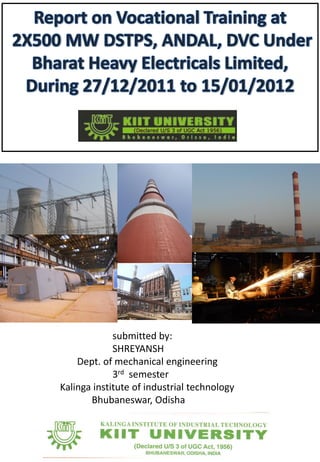
  • 1. submitted by: SHREYANSH Dept. of mechanical engineering 3rd semester Kalinga institute of industrial technology Bhubaneswar, Odisha
  • 2. BHARAT HEAVY ELECTRICALS LIMITED (BHEL) is one of the oldest and largest state owned engineering and manufacturing enterprise in India in the energy related and infrastructure sector which includes Power, Railways transmission and distribution, Oil and Gas sector and many more. It is the 12th largest power equipment manufacturer in the world. BHEL was established more than 50 years ago, ushering in indigenous Heavy electrical equipments industry in India. The company has been earning profits continuously since 1971-72 and paying dividends since 1976-77. In India , 72 % of total power generated in India is produced by equipments manufactured by BHEL. It is one of the India’s largest public sector Undertakings or PSUs, known as the “Navaratnas” or “The nine jewels”. Bharat Heavy Electrical Limited is the 12th largest power equipment producer in the world. BHEL have exported their products and services to more than 70 countries. BHEL had cumulatively installed capacity of over 8,500 MW outside of India in 21 countries, including Malaysia, Iraq, The UAE, Egypt and New Zealand. BHEL’s physical exports range from turnkey projects to after sales services. Most of BHEL’s manufacturing units and other entities have been accredited to Quality Management Systems (ISO 9001:2008), Environmental Management Systems (ISO 14001:2004) and Occupational Health & Safety Management Systems (OHSAS 18001:2007).
  • 3. DSTPS: ANDAL 2X500 MW POWER PLANT This project report is submitted on the basis of self undergone first hand vocational training at Durgapur Steel Thermal Power Stations(DSTPS), from 27th December 2011 to 15th January 2012. In this power plant there are 2 units, each capable of generating 500 MW of power, of which one is under construction and other is capable of running at full load, manufactured by M/S. BHEL who has been awarded this contract on turnkey basis by Damodar Valley Corporation (DVC), the owner of this project. Name of project: 2X500 MW DURGAPUR STEEL THERMAL POWER STATION Location: Andal, Durgapur, Dist- Burdwan (West Bengal) Name of the customer: Damodar Valley corporation(DVC) Name of the contractor: Bharat Heavy Electricals Limited Area: The total area of the plant is 3.47 sq-km. Seismological data: The area falls in zone-3 of seismological zone. Communication: The site is located 0.5km away from NH2. the nearest railway station is Andal station is about 3 km away from the site.
  • 4. We express our sincere gratitude to all those people who have been associated with the training and have helped us with it and made it a worthwhile experience. Firstly we extend our thanks to Mr. Prashanta Panja, Mr. R.K. Verma, Mr. Suchand Roy, Mr. P.K. Mukhopadhay, Mr. Rahul kumar, Mr. Himadri Shekhar Pal, Mr. Rupak Mitra, Mr. Nabarun Sarkar , Mr. Dinesh Mahapatro, Mr. Gopal Pal, Mr. Anirban Joardar, Mr. Saugata Chakraborty, Mr. Palash Pramanick who have shared their opinions and experiences through which we received the required information crucial for our report. Finally,we express our thanks to Mr. Shekhar Bhattacharjee, General Manager, DSTPS, PSER, BHEL without whose support and guidance this project would not have been complete. We thank all BHEL personnel for their guidance and support. Yours sincerely,
  • 5.  Schedule of Training  Power Plant as a System  Technical detail of components of Thermal Power Plant  Boiler  Turbine  Generator Electrostatic precipitator Transformer  BOP  Coal Handling Plant(CHP)  Ash Handling Plant(AHP)  Water Package  Station Control and Instrumentation (C&I)  Cooling System  Cooling Water  Auxiliary Cooling Water  Equipment Cooling Water  Natural Draft Cooling Tower  Air Conditioning and Ventilation System  Generator Cooling  Safety  Quality Material management Finance  Conclusion
  • 6. Date 1st Half 2nd Half 27/12/2011 to 31/12/2011 Boiler and Structural TG 02/01/2012 to 07/01/2012 Electrical Package BOP and Safety 09/01/2012 to 12/01/2012 Switchyard, Water Package and Quality C&I 13/01/2012 to 15/01/2012 Civil(Power House) and Ash Handling Package Chimney, NDCT, MM, Finance
  • 7.
  • 8. Introduction A thermal power station is a power plant in which the prime mover is driven using steam. Water is heated, which turns into steam and spins a steam turbine which drives an electrical generator. After it passes through the turbine, the steam is condensed in a condenser and recycled to where it was heated; this is known as a Rankine cycle. The greatest variation in the design of thermal power stations is due to the different fuel sources. The Durgapur Steel Thermal Power Station is a coal-fired thermal power station having 2 units of 500 MW capacity each. Overview of DSTPS Bird Eye View of DSTPS (not to scale) The 2x500 MW Durgapur Steel Thermal Power Station is located approximately 4 Kilometres north of the Damodar river and 8 Kilometres North-West of Durgapur town covering an area of approximately 4 sq. Kms. The power station draws its raw water from the Damodar river and treats this raw water using appropriate water treatments systems present on the site before using the water. The fuel supply (i.e. coal and diesel oil) for the plant is supplied through railway. Trains bring the coal and diesel oil into the site and is unloaded using appropriate fuel pumping systems for diesel oil and coal unloading and processing system for unloading coal. There is a coal-handling plant present on the site to process and stack the unloaded coal until it is needed in the boiler which is present within the power block of the power station. Bird Eye View of DSTPS (not to scale)
  • 9. The power block is located at the very center of the power station. Within the power block, the transformer yard sits at the northern-most point. The power house is located immediately south of the transformer yard. Moving southwards, the two boiler for the two units come next, followed by a pair of ESPs (one for each of the units), and finally a common chimney. The boiler burns the fuels to produce steam which is used in the power house (TG building) to generate electricity, which is then stepped up in the transformer yard and transmitted to the switchyard (which is located about 500 meters northwest of the power block). The switchyard routes the power into the appropriated transmission line. The flue gas produced in the boiler is passed through the ESPs before being released into the atmosphere through the chimney. The ash produced within the boiler is converted into ash slurry by mixing it with water and then sent to the ash pond situated at the eastern-most end of the premises. The cooling water required by the power plant for its operation is obtained from a pair of NDCTs situated 500 meters northeast of the power block. Fundamental Principle of Operation : The Rankine Cycle The Rankine Cycle is a thermodynamic cycle that produces mechanical work by transferring heat from a heat source to a heat sink. There are four processes in the Rankine cycle. These states are identified by numbers (in brown) in the diagram . Process 1-2: The working fluid is pumped from low to high pressure. As the fluid is a liquid at this stage the pump requires little input energy. Process 2-3: The high pressure liquid enters a boiler where it is heated at constant pressure by an external heat source to become a dry saturated vapor. Process 3-4: The dry saturated vapor expands through a turbine, thus generating mechanical power. This decreases the temperature and pressure of the vapor, and some condensation may occur. Process 4-1: The wet vapor then enters a condenser where it is condensed at a constant temperature to become a saturated liquid.
  • 10. The Water-Steam Cycle being actually used at DSTPS The water-steam cycle which is being used in each of the 500 MW units of DSTPS is an improved variant of the basic Rankine cycle. The cycle begins at the drum of the boiler. The water which is present in the drum is drawn to the bottom of the boiler through a set of down-comers and pumped back up through the water-wall (wall of water-carrying pipes surrounding the boiler flue) and circulated through the radiant-roof (a roof constructed using similar water-carrying pipes) before being sent back to the drum. As the water inside the drum heats up and produces wet steam, it is extracted from the top of the drum and is sent to the superheater to form superheated steam. The superheated steam so obtained is called the Main Steam and it has a pressure and temperature of 150 Kg/cm2 and 540° C respectively. This steam is sent to the High-Pressure (HP) turbine through the Main Steam Line. The steam discharged from the HP turbine is at a pressure and temperature of 35 Kg/cm2 and 250° C - 300° C and is called the Cold-Reheat Steam. This steam is circulated through the reheater present in the boiler so that it collects heat from the flue gas and its temperature and pressure is increased to 540° C and 45 Kg/cm2. The steam obtained after reheating the Cold-Reheat Steam is called the Hot-Reheat Steam. The Hot-Reheat Steam is sent to the Intermediate-Pressure (IP) Turbine and the discharge from the IP turbine is fed into the Low-Pressure (LP) turbine. All three turbines (HP, IP and LP) are coupled to a common driveshaft which drives the 500 MW alternator at 3000 RPM. The discharge from the LP turbine is fed into the condenser. The water produced when the steam condenses is collected in a hotwell bellow the condenser and is extracted using the Condensate-Extraction Pump (CEP) and circulated through the Low-Pressure heaters (LP heaters) to collect heat. The LP heaters are heated using the steam bled from the LP turbine. The discharge from the LP heaters is passed through the Deaerator and then pumped using the Boiler-Feedwater Pump (BFP). The high- pressure discharge from the BFP is further heated in the High-Pressure heaters (HP heater) and then circulated through the Economizer before being sent back to the boiler drum. The HP heaters are heated using the steam bled from the HP and IP turbines. All the bled steam obtained from the turbines are condensed and re-injected into the water-steam cycle. This cycle is more efficient than the basic Rankine cycle because a lot heat exchangers are provided in this system (for instance, LP and HP heaters, economizer, etc) to recover and reuse heat that would otherwise have been wasted in case of the basic cycle.
  • 11. This cycle is more efficient than the basic Rankine cycle because a lot heat exchangers are provided in this system (for instance, LP and HP heaters, economizer, etc) to recover and reuse heat that would otherwise have been wasted in case of the basic cycle. Boiler The boiler (also known as the Steam Generator) is the heat source for the water-steam cycle being used in the power plant. There are two double-pass water-tube boilers at DSTPS, one for each of the 500 MW units. Structure Each of the two-pass boilers being used at DSTPS is a hollow rectangular structure whose walls (water-cooled and steam-cooled walls) and roof (radiant roof) have been constructed using pipes carrying water (in case of the first pass) or steam (in case of the second pass). The fuel is burnt inside this hollow structure producing a fireball and the resulting heat is absorbed by the water and steam-cooled walls and roof. Additionally, the flue produced due to burning of fuel is passed over various water- carrying or steam- carrying coils (for instance, superheaters, reheaters, economizer, etc), which are hanged from proper supports in the path of the flue. The boiler drum, a hollow horizontally-laid cylindrical structure, whose purpose is to separate the steam from the water, is located above the radiant roof at a height of 75 meters from ground level (0m level). A windbox arrangement is provided at each of the four corners of the boiler to supply air for combustion. Also, the diesel fuel and coal is supplied through appropriate arrangements from the four corners of the boiler. Fuel and Air Supply The air supply for combustion in each of the 500 MW boilers is provided by two Primary Air fans (PA fans) operating at 1490 RPM and two Forced-Draft fans (FD fans) operating at 1460 RPM. The air is preheated within Air-PreHeater (APH) units (two for each boiler) before being fed into the furnace in order to improve efficiency. The secondary air provided from the FD fans is directly fed into the furnace and helps maintain the air circulation or draft within the furnace. Coal, the primary fuel for this power plant, is supplied from the Coal-Handling Plant through a system of conveyer belts into 10 coal bunkers for each of the 500 MW units. The chunks of coal received in the coal bunker are 40 cm or less in their largest dimension. The coal chunks are pulverized in Coal-Pulverizer mills into coal particles that are 40 microns or less in their largest dimension. There are 10 pulverizer mills for each boiler, one placed beneath each of the 10 coal bunkers.
  • 12. The air supplied from the PA fans, after being passed through the APH units is used to blow the pulverized coal from the mills into the furnace. The air flow from the PA fans can be altered by controlling the pitch of the impeller blades and the air temperature can be controlled by mixing cold air, which is obtained from a bypass duct from the discharge of the PA fans, with the preheated primary air being discharged from the APH units. The pulverized coal obtained from the 10 mills is fed into the furnace at 10 separate levels. Light Diesel Oil (LDO) and Heavy Fuel Oil (HFO) are used in the boiler during light-up to create the initial fireball so that the pulverized coal can be ignited. HFO is injected into the furnace using atomizer nozzles at 5 levels, which are situated below the 10 levels at which coal is injected. At the bottom-most level, LDO is also injected along with HFO through a separate atomizer nozzle. Each of the 5 levels for HFO and LDO have retractable igniter arrangements that produce the spark require to ignite the fuel. HFO is preferred over LDO for firing the plant because its less expensive than LDO. However, HFO is highly viscous at normal temperature and cannot be pumped. So LDO is required to initially light-up the boiler and produce steam, which is then used to heat the HFO to liquefy and pump it through the HFO lines. Also, HFO lines are traced by steam lines to keep the HFO in liquid state while within the lines. Path of the Flue The flue gases are generated within the furnace when the fuel burns. This flue travels upward passing over the superheater and reheater coils, passes through the goose neck and then comes back downwards while passing over the Low Temperature SuperHeater (LTSH) coils, the Economizer coils, and the Air PreHeaters. The flue exiting the APH units are passed through the Electro-Static Precipitator (ESP) before being sucked through the ID fans (Induced Draft fans), which can opearate at speeds upto 560 RPM, and then released into the atmosphere through the chimney. Super-Heater and Re-Heater The super-heater is a heat-exchanger that transfers heat from the flue gas into wet steam to convert it into dry saturated steam which can then be sent to the HP turbine through the Main Steam line. The Re-Heater is a heat-exchanger that transfers heat from the flue gas into Cold-Reheat Steam, which is essentially the steam discharged from the HP turbine. This is done because the Cold- Reheat steam is at within the temperature range of 250° C - 300° C and is not suitable for use in the IP turbine directly. Hence, the Cold-Reheat Steam is heated in the Re-Heater to obtain what is known as Hot-Reheat Steam, whose temperature is around 540° C, before feeding it to the IP turbine. Economizer The Economizer is a heat-exchanger that transfers heat from the flue gas into boiler feed-water before sending it to the boiler drum. This improves the overall efficiency of the boiler. Air Pre-Heater (APH) The Air Pre-Heater (APH) is a rotary heat-exchanger that transfers heat from the flue gas into the air that is being supplied into the furnace by the FD and PA fans. Preheating the feed-air also helps improve the overall efficiency of the boiler. Boiler Equipment Cooling System Various mechanically-moving equipment, that are required for operation of the boiler, produce a lot of heat and need to be explicitly cooled. There is a cooling water circuit called the Boiler Equipment Cooling Water (BCW) circuit that transfers heat from the heat-generating machinery to the Auxiliary Cooling Water (ACW) circuit, which in turn dissipates the heat into the atmosphere through the NDCTs. Lubrication and Sealing Systems Various mechanically-moving equipment, that are required for operation of the boiler, have associated lubrication and sealing systems. Lubrication is usually done using oil. Seals between mechanically-moving parts are maintained using pressurized air or pressurized oil.
  • 13. Turbine A turbine is a rotary engine that extracts energy from a fluid flow and converts it into useful work. The simplest turbines have one moving part, a rotor assembly, which is a shaft or drum with blades attached. Moving fluid acts on the blades, or the blades react to the flow, so that they move and impart rotational energy to the rotor. There are three steam turbines for each 500 MW unit driving a common driveshaft. They are •The High-Pressure (HP) Turbine •The Intermediate-Pressure (IP)Turbine •The Low-Pressure (LP)Turbine The HP Turbine is fed from the Main Steam line at a pressure and temperature of 150 Kg/cm2 and 540°C. The discharge from the HP turbine, which is at a pressure of 35 kg/cm2 and temperature between 250° C - 300° C, is sent through the Cold-Reheat line to the re-heater. The IP turbine is supplied with steam at a pressure and temperature of 45 kg/cm2 and 540° C from the Hot-Reheat line returning from the re-heater. The discharge from the IP turbine is fed into the LP turbine. The discharge from the LP turbine is dumped into the condenser. The waste steam or bled steam discharged from each of the turbines is utilized to heat High- Pressure (HP) heaters (fed from the HPT and IPT) and Low-Pressure (LP) heaters (fed from the LPT), which in turn heat the boiler feed-water before sending the boiler feed-water to the economizer. The bled steam is condensed in the gland steam condenser and combined with the condensate from the main condenser. Deaerator The deaerator is provided to extract dissolved gases (such as oxygen) from the condensate. The water is heated in the deaerator in direct contact with dry steam, which causes it to release the dissolved gases. The gases are absorbed in the steam which is vented out.
  • 14. Condenser & Condenser-Extraction Pump (CEP) The condenser is a heat-exchanger that condenses the steam discharged from the LP turbine. It is the heat sink for the water-steam cycle. The condenser is cooled by the Cooling Water (CW) obtained from the NDCT. The condensed steam discharged from the condenser is dumped into a hotwell (a reservoir) beneath the condenser. The discharge from the gland steam condenser is also dumped into the hotwell. The water collected in the hotwell is pumped out using the Condenser-Extraction Pump (CEP) and through the drain cooler, which further cools the condensate. Boiler Feed-water Pump (BFP) The boiler feed-water pump is the main pump responsible for maintaining circulation in the water-steam cycle. There are three BFPs for each 500 MW unit. Two of these are Turbine-Driven BFP (TDBFP) which are powered by taping out a small amount of steam from the discharge of the IP turbine. The third one is a Motor-Driven BFP (MDBFP), which is powered the largest auxiliary drive motor in power block, consuming 10 MW of power. LP and HP heaters The LP and HP heaters are heat-exchangers that transfer heat into the boiler feed-water from the bled steam discharged from the HP, IP and LP turbines. The bled steam from the HP and IP turbines feed the HP heaters. The bled stream from the LP turbine feeds the LP heaters. Turbine Equipment Cooling System Various mechanically-moving equipment, that are present in the TG building, need to be explicit cooling for their operation. There is a cooling water circuit called the Equipment Cooling Water (ECW) circuit that transfers heat from the heat-generating machinery to the Auxiliary Cooling Water (ACW) circuit, which in turn dissipates the heat into the atmosphere through the NDCTs. Lubrication and Sealing Systems Various mechanically-moving equipment, that are present in the TG building, have associated lubrication and sealing systems. Lubrication is usually done using oil. Seals between mechanically- moving parts are maintained using pressurized air or pressurized oil. Generator At DSTPS, a 500 MW alternator (having 2 poles and synchronous speed of 3000 rpm), for each 500MW unit, is mechanically coupled with the driveshaft of the corresponding set of turbines for the unit to produce approximate 21.5 KV of voltage at a frequency of 50 Hz. The power factor of the alternator is 0.85. Excitation System The synchronous generator, which is coupled with the turbine to produce electric power in a thermal power plant, needs a dc excitation for its rotating field coils. Mainly two types of dc excitation is used i) Static Excitation ii) Brushless excitation.
  • 15. To eliminate commutation loss and increase overall efficiency, Brushless excitation is preferred at 250 MWs and above. With the advent of mechanically robust silicone diode capable of converting A.C. to D.C. at a high power levels, brushless excitation system has become popular and being employed. At DSTPS, a brushless excitation system is employed that uses a set of 144 power diodes on the rotor assembly for rectification of the exciter-output, and an on-shaft Permanent-Magnet Generator supplying the stationary field-coils of the exciter. The excitation current on larger generators can reach 10 kA. The amount of excitation power ranges between 0.5-3% of the generator output power. The exciter field coils are on the stator and its armature is on the rotor. The AC output from the exciter armature is fed through a set of diodes that are also mounted on the rotor to produce a DC voltage. This is fed directly to the field coils of the main alternator, which are also located on the rotor. The silicon diodes are arranged on the rectifier wheels in three configurations. The diodes are so made that the contact pressure increases during rotation due to the centrifugal force. There are 144 diodes on the rotating shaft to organize a bridge rectification scheme. A Digital Automatic Voltage Regulator (DAVR) receives an AC feedback from the output of the exciter armature and controls the input of the exciter field by modulating the output of the PMG. The input of the exciter field is varied between 0-220 volts DC.
  • 16. Electrostatic precipitators are designed to deal mostly with coal fired refineries. In this country, we have more coal then we know what to do with, however, it does not burn cleanly. Lately though, coal has been making a comeback in big industries. Electrostatic precipitators separate the clean from the unclean, and in the end what you have is a refinery that is releasing air that is almost 99% cleaner. Figure 1 shows an overhead view of how an electrostatic precipitator works. Figure 2 illustrates the operation of an electrostatic precipitator in its simplest form. This procedure will inform you on what makes up an electrostatic precipitator and how they work once the pieces are put together. The main components of an ESP are: Collecting Plates Collecting plates are made from rolled steel, and are welded together in the factory to reduce the installation time at the jobsite. Each plate contains electrodes which are positively charged.
  • 17. When the particulate gas enters the electrostatic precipitator and is struck with a negative charge electrode, the positively charged plates act as a magnet and pull the particulate gas to them. Collecting Electrode (-ve) Emitting Electrode (+ve) Discharge Electrodes Discharging electrodes are a high voltage unit that negatively charges the particulate gas as it enters. . The discharge electrode is mounted to a frame in between the collecting plates. The negatively charged particles that pass by the electrodes and then the counter charge of the collecting plates; make the particulate like the magnet on a refrigerator. Rappers Rappers are used to dislodge the particulate from the collecting plates. Mechanical rappers work like a hammer and chisel. The hammers are attached to the rods which are attached to a rolling cam above. The cam is turned by an external motor and gear. Hoppers Hoppers look like upside down triangular prisms. They are generally made of steel, and their only purpose is to store particulate. Once the rappers have done their job, it is then time to collect the falling particulate. The hoppers can have piping running to them for a vacuum operated system which will pull the particulate from the hoppers and bring it to a remote storage facility.
  • 18. There are basically 4 types of transformers in the whole power plant for transmission to and from the grid and also for supplying power by stepping down the voltage. Which are: Station transformer(ST) Generating transformer(GT) Unit transformer(UT) Unit auxiliary transformer(UAT) There are 1 ST, 3 GTs, 2 UTs, and 2 UATs per unit in the 2X500 MW DSTPS, DVC, Andal site. Station Transformer: The station transformers are used to power up the power plant initially by stepping down the voltage coming from the grid. It steps down the high grid voltage of 400KV to 11KV and this voltage is used to start the power plant. Generating transformer: Generating transformers are connected to the alternator which steps up the output voltage of alternator (21.5KV) to 400KV & supplies to the grid. Unit Transformer: The unit transformers supply the unit (i.e. the power plant) by stepping down the generated voltage of 21.5 KV to 11KV. Unit Auxiliary Transformer: These transformers are used to supply the auxiliary drives and equipments. It takes a input voltage of 11KV and establishes an output voltage of 3.3 KV.
  • 19. Industrial Safety is the area of safety engineering and public health that deals with the protection of workers' health, through control of the work environment to reduce or eliminate hazards. Industrial accidents and unsafe working conditions can result in temporary or permanent injury, illness, or even death. Common physical hazards include ambient heat, burns, noise, vibration, sudden pressure changes, radiation, and electric shock. Industrial safety engineers attempt to eliminate hazards at their source or to reduce their intensity. If this is impossible, workers are required to wear protective equipment. Depending on the hazard, this equipment may include safety glasses, earplugs or earmuffs, face masks, heat or radiation protection suits, boots, gloves, and helmets. To be effective, however, the protective equipment must be appropriate, properly maintained, and worn by the worker. Welder Wearing Protective Eyewear A welder wears protective eyewear to shield his eyes from the actinic rays produced by a welding arc. Intense bright light of this sort can be very damaging to the inner lining of the eye and may result in partial or permanent blindness. Although sunglasses with a light tint are sufficient for eye protection from the sun, a much deeper tint is required to protect the eyes during welding operations. Fire Protection, Detection And Alarm System: INTRODUCTION The fire protection, detection and alarm system is provided for thermal power station to protect the plant against fire damage to avoid loss of life and property. Fire detection system is provided to detect fire in its incipient stage and to actuate the fire protection system to extinguish fire. Alarm system gives warning in case of fire to prompt fire fighting staff and other operation personnel to take necessary action. In addition to fixed automatic system, portable and mobile systems are also provided for fire extinguishing.
  • 20. Fire protection system: Automatic fixed foam system for fuel oil storage tanks Automatic fixed foam system is envisaged for main HFO/LSHS and LDO storage tanks. In case of fire, the foam system for the respective tank gets automatically activated on detection of fire by probe type heat detectors provided inside the fuel oil tanks resulting in pouring of the foam water mixture on the oil surface inside the tank and foam blanketing the burning oil surface thereby cutting the oxygen supply and extinguishment of fire. Fire detection and alarm system Fire detectors are provided in all areas and buildings of thermal power stations to detect the fire in its incipient stage, give alarm and actuate the fixed fire protection system provided to extinguish the fire. Type of fire detectors for various areas depends upon the fire risks. In addition to automatic fire detectors, manual call points are also provided throughout the power station for manually initiating alarm in case fire is noticed by some body. Fire extinguishing safety pipes around LDO tanks Always use helmet at workplace
  • 21. TOTAL COOLING SYSTEM OF THE POWER PLANT The main components of the COOLING SYSTEM of the power plant are--- Cooling Water System (CW) Auxiliary Cooling Water System (ACW) De-Mineralized/Equipment Cooling Water System (DMCW/ECW) Air Conditioning (AC) & Air Ventilation System Generator Cooling System Cooling Water System (CW):- The Cooling Water System (CW) is used to cool & condensed the exhaust steam from Low Pressure Turbine (LPT) in the condenser. The exhaust steam needs to loose huge amount of heat energy to be condensed into the water particle. There is a clarified water pond just behind the Cool Water pump house. The pump delivers the water from the pond to the inside of the condenser. The pumps of the Cool Water pump house driven by 3-phase Induction Motor. The CW system is a closed loop water cycle. The cool water goes to the condenser & gains some heat energy which comes back to the NDCT (Natural Draft Cooling Tower) where it looses heat energy naturally and goes back to the cooling water pond to be pumped out by CW pumps. The main CW supply line from the CW pump house also have another branching after CW header goes to Boiler Cooling Pump (BCP). It also uses for cooling of boiler equipments like Mills, FD fans, PA fans, ID fans. Cooling Tower (NDCT) CW Pump House Auxiliary Cooling Water System (ACW) :- The Auxiliary Cooling Water (ACW) system is also a closed loop water cycle which is almost cycling in the same path as of Cooling Water (CW) system. At first the ACW delivered to the Heat Exchangers from the clarified water tank where it is used like a primary coolant to cool the De- Mineralized Cooling Water (DMCW) or Equipment Cooling Water (ECW). At heat exchangers the ACW is heated by absorbing some heat energy from DMCW. After that it opened in the return line of the CW & then followed the same cyclic path as CW, only it goes to the heat exchangers instead of condenser & comes back to the NDCT with CW.
  • 22. Simple Flow Cycle of ACW De-Mineralized/Equipment Cooling Water System (DMCW/ECW) :- The DMCW or ECW system is another closed loop water cooling system which is the only system using the De-Mineralized (DM) water from DM water plant. It is called ECW because it is only used in those all equipments of the plant which need to be cooled (mainly rotating equipments). The DM water comes to the DMCW header initially from the DM water plant. Then DMCW pumps used to send the DMCW to the Plate Heat Exchangers (PHE) where it looses heat to ACW and goes to all the equipments need to be cooled. From the equipments it returns to the DMCW header. Thus the closed loop cycle is completed for DMCW. Simple Flow Cycle of DMCW/ECW Air Conditioning (AC) & Air Ventilation System :- The Air Conditioning (AC) system is an efficient closed loop system to keep the equipments and control panels of Control rooms cool. The fundamental concept of cooling the systems is by recycling air through the Diffuser and return Diffuser in the room. In this aforementioned process the air which gets out of the return diffuser is hot and is cooled in the Air Handling Unit (AHU).
  • 23. In the AHU unit the chiller water cools the air by extracting the heat from the hot air; simultaneously in this process the chiller water also gets hot and it is cooled in the AC plant. In the AC plant R22 is used as a refrigerant which cools the chiller water in the same way it cools the air in the AHU. In the AC plant there is a refrigeration cycle to cool the refrigerant R22 which gains heat while cooling the chiller water. In the refrigerant cycle there are 4 phases, Compressor, Condenser, Expansion Valve and Evaporator. The relatively hot R22 is cooled by some cooling water in the compressor chamber. It looses further heat in the Condenser & the Expansion Valve while go to the Evaporator. In Evaporator it cools the chiller water & goes back again to the Compressor. Flow Diagram of Air- Conditioning System The Air Ventilation System is an auxiliary air cooling or conditioning system which is used to keep the environment cool of those auxiliary rooms (switch-gear rooms/ MCC rooms) which does not need to be cooled from AHU like the control rooms. The Air Ventilation System is an opened loop system where air is sucked from atmosphere & delivered to the supply rooms. The cooling of the air in this system is done in the Air Washer Room. In the Air Washer Room there is an open end at a side of the room. Air is sucked by some fans from the atmospheres and goes through a box where multiple plates placed vertically in the path of air flow. When air flows through those plates some cooling water is sprayed on the plates which wash the air hence resulting for supply of cool air from the Air Washer Room. Generator Cooling System:- There are two separate & isolated cooling methods executed simultaneously in the generator cooling system. Water & Hydrogen (H2) are used respectively in the two different cooling methods. The water for the water cooling method is supplied from generator cool water pum p to a header tube situated above the generator. In the header tube there is a coolant material which mixed with the water & the mixture cools through the outer surface of generator in a re- cyclic process, where the H2 is used to cool the inner chamber of generator (The inner chamber is filled up by H2). As the mixture of air & H2 is highly explosive there must be some precaution to prevent the leakage of H2 from the inner chamber of generator.
  • 24. WATER TREATMENT PLANT In a coal fired thermal power plant, water is required for various applications such as condenser cooling, ash disposal, heat cycle make up, equipment cooling, service water, potable applications and other miscellaneous applications. Raw water available from river, canal etc. is required to be treated to suit the particular application. Various types of treated water used in a coal fired power stations are: a) Clarified water as cooling tower make-up and service water b) Demineralised water for heat cycle make-up, equipment cooling system makeup, condensate polishing plant regeneration etc. c) Filtered & disinfected water for potable water requirement. Raw Water Reservoir and Pump House i) The raw water from river, canal etc. is brought up to plant raw water reservoir located within the plant boundary. Reservoir is open type in two compartments. Capacity of reservoir is selected based on the reliability of raw water source such that storage can meet the plant water requirement during period of non availability of water from the source. ii) Raw water from plant reservoir is supplied to pre-treatment plant by raw water pumps. Emergency water requirement for ash handling plant, when running in wet mode, is also supplied from discharge of raw water pumps. Pre-Treatment (PT) Plant i) The pre-treatment plant produces clarified water for meeting the requirement of clarified water applications of the power plant viz. cooling tower makeup, service water and input water for producing potable and DM water. DM Plant i) DM Plant is meant to supply demineralised water for power cycle/ condensate make-up, make-up for equipment auxiliary cooling system, CPU regeneration, HP/LP dosing system etc. Conventional demineralising plant (DM), i.e. process of removing the mineral salts from water by ion-exchange method, consisting of cation, anion and mixed bed polisher, is used for production of demineralised water from filtered water with total dissolved salts (TDS) level of up to 500 ppm. Raw water reservoir
  • 25. Control & instrumentation is a department which deals with the process of controlling a device or a machine in a specific way as per the requirement of the user. This is the brain of a power plant which is connected to all the fields of the power station. The main control room of the 2x500 MW DSTPS, DVC, andal is situated at the top of the power house from where all the equipments & machines are controlled through computerized system. The input given to the computer from the input device goes to the processor & the output of the processor goes to the relay device in the form of a voltage pulse & the relay device is operated according to the given instruction.PID controllers are used vastly in the this control system. Besides the main control room, there are other control rooms such as control room for ESP,ID fans, CHP, AHP, switchyard etc. The main feature of this control system is the whole system of the plant can be controlled from the main control room through a single computer.
  • 26. Ash Handling Plant: In a coal based thermal power plant, huge amount of ash is generated which has to be disposed off continuously. Typically for a 2x500 MW plant based on indigenous coal, the amount of ash generated is around 300 to 400 TPH depending on gross calorific value and ash content of worst coal. The ash handling system covers evacuation of ash and disposal in wet and dry form. The ash is produced in two forms viz. fly ash which is of fine texture and bottom ash which is comparatively coarser. The ash entrained in the flue gases and captured in electro-static precipitator (ESP) is termed as fly ash and the ash which falls at the bottom of the boiler furnace is known as bottom ash. Small quantities of ash are also collected in the air preheater, economizer and stack. Ash Disposal System Dry disposal: The dry fly ash from ESP hoppers is conveyed to intermediate surge hoppers by vacuum/pressure conveying, which are located as close to the ESP as possible. Fly ash collected in intermediate surge hoppers is pneumatically conveyed to storage silos in a separate area near the plant boundary, with independent access from where it is unloaded into the open/ closed trucks or in railway wagons. Wet disposal: While bottom ash handling and disposal shall be in wet mode, wet disposal of fly ash is to be resorted during initial period of plant operation till 100% fly ash utilization is achieved or during emergency when dry disposal is not possible. Fly ash and bottom ash slurry is led to common ash slurry sump. Pre-treatment plant clarifier sludge is also discharged into common ash slurry pit. This combined slurry is then pumped to the ash pond through ash slurry pipelines by centrifugal type low speed ash slurry pumps. The ash slurry pumps may be required to be placed in series (maximum four) for meeting high head requirement while pumping to long distances and higher elevations. Ash Water System i) The entire water requirement of the ash handling system is met from cooling tower blow down of the station and decanted recovery water from the ash pond. A connection from raw water is also provided for fast fill and emergency makeup purposes. Clear water as necessary for equipment sealing and cooling is provided from station clarified water. DM water may also be used for cooling purposes in closed cycle. In case of once through system in coastal stations using sea water, water for ash handling is tapped from return header of CW system. ii) Ash water system consists of ash water sump, HP water pumps, LP water pumps, economiser ash water pumps etc. BAHP (bottom ash high pressure) water pumps are used to extract bottom ash from both units intermittently and sequentially in case of jet pump system and continuously in case of SSC system. In case of jet pump system, BAHP pump supply water for jet pumps, BA hopper flushing, seal trough & gate housing flushing etc. In case of SSC system, BAHP pumps supply water for quenching, BA trench jetting, seal trough flushing, gate cooling, BA sump agitation etc.
  • 27. In case of jet pump system, BALP (bottom ash low pressure) pumps supply water for refractory cooling, BA hopper cooling water to maintain hopper water at 60 deg C, BA hopper fill and make up, seal trough make up/fill, slurry sump hopper make up water etc. In case of SSC system, BALP pumps supply water for refractory cooling, cooling water for upper trough of SSC to maintain water temp. at 60 deg C, seal trough make up, cooling water to inspection windows, wash water to grinder, BA sump make up, ash slurry sump make up etc. Fly ash HP water pumps (FAHP) supply water to wetting heads, air washers, F.A. slurry/trench jetting, combined ash slurry sump make up, combined ash slurry sump agitation etc. Seal/cooling water pumps are provided for gland sealing of slurry pumps, vacuum pumps cooling of compressors and sealing water requirement of clinker grinders. Alternatively, plant DM water can be used in closed cycle for cooling purpose. In order to conserve water used in wet ash disposal, an ash water recovery system is provided to recirculate the decanted water from the ash pond and re-using this water for ash handling purposes. BA hopper cooling water overflow can also be re-circulated after treating in settling tank and surge tank. Flue gas collecting silo Layout for fly ash system in ESP Ash pond
  • 28. CHP is (C- Coal, H- Handling, P- Plant) a plant which handles the coal from its receipt to transporting it to Boiler and store in Bunkers. It also processes the raw coal to make it suitable for Boiler Opeartion. Receipt of Coal: Normally Thermal Power Station receives the coal by three modes of transportation. 1. By Railway (80-90% of the requirement is fulfilled by this way) 2. By Road ( if required 5-10% of the requirement is fulfilled by this way ) 3. By Arial ropeways Arial ropeway is available only to the power stations which are near the coal mines) In our case railway system is used. hopper It is the area where the coal falls from the wagon tripplers or it is the area where coal is unloaded.its length is 270m.ata time 22 wagons can be unloaded there Major auxiliaries of CHP:- 1. Wagon Tipplers 2. Paddle feeder 3. Conveyor Belts 4. Coal Crushers 5. Trippers 6. Electromagnetic Separators. 7. Dust extraction systems Wagon Tripplers:- These are the giant machines having gear boxes and motor assembly and are used to unload the coal wagons into coal hoppers in very less time (e.g. 20 wagons/hr. or more). Paddle Feeders:- These are electromagnetic paddle feeders or sometimes in the form of dragging chains which are provided below the coal hoppers. This equipment is used for controlled removal of coal from coal hoppers. There is a blade arrangement involved to move the coal from hopper to coal bed the coal bed and finally it is transferred to the conveyor belt .total there are 4 paddle feeders. Anti collision sensor is provided between them and s switch trips if they come between 6m.it has a capacity of carrying 5500 metric tone coal and having length 11m.
  • 29. Conveyor Belts:- These are the synthetic rubber belts which move on metallic rollers called idlers and are used for shifting of coal from one place to other places.they are provided with belt sway switch to stop sideways belt shift ,pull cord switch for accdidental shutoff of conveyor .they operate from head pulley to tail pulley as shown in this figure. Coal Crushers We receive the coal in the form of odd shaped lumps. These lumps are to be crushed to required size. These lumps are crushed by coal crushers. Trippers:- These are the motorized or manually operated machines and are used for feeding the coal to different coal bunkers as per their requirement. Electromagnetic Separators:- Electromagnets are used for removing of Iron and magnetic impurities from the coal Dust Extraction System:- This system is provided in CHP for suppression of coal dust in coal handling plant. Operational Cycles:- 1. Normal Bunkering cycle. 2. Stacking cycle. 3. Reclaiming Cycle. Normal Bunkering Cycle:- Shifting of coal received from coal wagons directly to coal bunkers is normal bunkering cycle. Stacking Cycle:- When there is no coal requirement at coal bunkers even then CHP has to unload the received coal which is stacked at open ground called yard. This is stacking cycle. Reclaiming Cycle:- As and when coal wagons are not available the requirement of coal bunkers is fulfilled from the stacked coal this is reclaiming cycle.
  • 30. Quality It involves Error Free OR Defect Free Performance of an equipment. The word applies to a state of a product relating to Fitness for its purpose or use, Conformance to specified requirements, The totality of features and characteristics of it or service that bears on its ability to satisfy the stated and/or implied needs. It should meet anticipating customer’srequirements, stated or implied • At a given time and over a period of time • At a price the customer can afford and is willing to pay _ Introducing new and better products into the market faster than competitor _ Continuously bringing down the cost of manufacturing The guidelines for achieving optimum quality of a product maintained in most BHEL projects as this one are as follows:- Inspection management Quality control management Quality Assurance Management – ISO 9000 Total Quality Management – EFQM- (European Foundation for Quality Management: EFQM is the most widely-used Business Excellence Framework in Europe, with over 30,000 businesses using the Excellence Model to improve performance and increase their bottom-line. The Excellence Model is a non-prescriptive framework that allows for enough flexibility to be adapted to any type of organisation, regardless of size or sector
  • 31. PDCA A plan do check act cycle(PDCA) is briefly shown which is related to continuous quality improvement.It is an iterative four-step management method used in business for the control and continuous improvement of processes and products. It is also known as the Deming circle. BHEL adheres to various standards such as iso 9001 for quality management ,iso 14001 for environmental policy framing and complianceto those and iso 18001 for Occupational Health and Safety Six Sigma Quality Six Sigma at many organizations simply means a measure of quality that strives for near perfection. Six Sigma is a disciplined, data-driven approach and methodology for eliminating defects (driving toward six standard deviations between the mean and the nearest specification limit) in any process — from manufacturing to transactional and from product to service. The statistical representation of Six Sigma describes quantitatively how a process is performing. To achieve Six Sigma, a process must not produce more than 3.4 defects per million opportunities. A Six Sigma defect is defined as anything outside of customer specifications. A Six Sigma opportunity is then the total quantity of chances for a defect
  • 32. Material Management: Materials management of the thermal power plant is designed to deal with campus planning and building design for the movement of materials, or with logistics that deal with the tangible components of a supply chain. Specifically, this covers the acquisition of spare parts and replacements, quality control of purchasing and ordering such parts, claiming insurance for accidents, lodging complaint for theft or other unforeseen incidents and the standards involved in ordering, and warehousing the said parts. In this project BHEL follows a policy excess/ deduction franchise of 5 lakh (INR) for insurance cases by paying a premium of 3 crores, which has been decided upon by thorough statistical analysis. The effective materials management plan builds from and enhances an institutional master plan by filling in the gaps and producing an environmentally responsible and efficient outcome. The MM department of BHEL deals with suppliers and the owner (DVC) of the project to provide an unbroken chain of components for production to manufacture goods on time for the customer base. BHEL has various supply units throughout India. Boiler parts come from Tiruchirapalli, turbine parts from Haridwar/Hyderabad, Transformers from Jhansi, C&I panels and equipments from Bangalore. Also many other electrical supplies come from Bhopal. A materials management plan may include planning guidelines or full design for the following: •Truck delivery and service vehicle routes, to reduce vehicle / pedestrian conflict •To increase accommodation and reduce queuing and vehicle idling. •Recycling, trash, and hazardous waste collection and removal, to increase waste diversion and reduce costs. •Service equipment and utility infrastructure relocation or concealment, to improve aesthetics and realize landscaping goals. •Regulatory and operation planning. •Material discrepancy list(MDL) is maintained by MM department to keep track of materials coming in less amount to that of agreed upon or material with damages(manufacturing or transportation).
  • 33. Finance: Finance dept maintains the cash flow to smoothen the whole transaction between vendor and client of a power plant to ensure proper erection and commissioning. After issuing of a material receipt certificate (MRC) by the MM dept. the finance dept. forms the bill and forward it to the customer/vendor and continue following up for speedy transaction. It also maintains records of taxes, MIR (monthly information report). The general role of finance dept is to: • ensure that there are adequate funds available to acquire the resources needed to help the organization achieve its objectives; • ensure costs are controlled; • ensure adequate cash flow; • establish and control profitability levels. Finance also prepares financial documents and final accounts for managers to use and for reporting purposes (AGM etc) and also identifies appropriate financial information prior to communicating this information to managers and decision-makers, in order that they may make informed judgments and decisions. BHEL follows AS7 standards for accounting purposes. The total installation cost for this thermal power plant offered by BHEL is 3500 crores. It excludes coal handling plant, water treatment plant and some other parts. Otherwise general cost for setting up a thermal power plant is 4.5 crore /MW.
  • 34. It has been a wonderful experience for me, to pursue a 20 days training under such an esteemed organization like Bharat Heavy Electricals Limited, who has devoted themselves to the service of the nation. It was my first experience of vocational training, and it was worthwhile; i learned a lot about generation of electricity in a Thermal Power Plant, which helped me to build a thorough knowledge about the structure and working of power sector. In near future, i will be looking forward to work in such an target oriented workplace environment where each personnel is so much dedicated to deliver optimum performance in their respective spheres.