
Recommended
More Related Content
What's hot
What's hot (20)
Similar to Sun WInd and light review- shravanthi gopalakrishnan.pdf
Similar to Sun WInd and light review- shravanthi gopalakrishnan.pdf (20)
More from Shravanthi Gopalakrishnan
Recently uploaded
Recently uploaded (20)
Sun WInd and light review- shravanthi gopalakrishnan.pdf
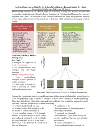
- 1. Navigation Matrix by Scale and Energy •Synergies, Bundles, Strategies and Techniques are categorized by heating, cooling, lighting, ventilation, power and combinations of these, and by the scales of building groups, buildings and building parts. Navigation by Design Strategy •Uses the nine levels of complexity to organize Bundles and Strategies and defi ne nested relationships where lower order strategies help build higher order strategies. Navigation by Climate •Helps identify the Strategies applicable to all climates and those useful when designing in a particular climate. Analysis of sun wind and light for the design of a building in a Tropical wet and dry climate Sun wind and light by Mark DeKay and GZ Brown The knowledge contained in Sun, Wind & Light can be accessed in many ways. Because it is structured in a modular way (as Synergies, Bundles, Design Strategies and Techniques) and because there are many ways that these “parts” can be related to each other and combined into larger design patterns, there are several means offered to access the content and to determine which components the designer wants to employ. Navigation Matrix by Design Strategy map Key Points • Strategies are organized in levels of complexity. • Less complex/smaller scale strategies help build larger strategies. • Every strategy has a context. • More complex/larger strategies organize patterns of smaller strategies. • A full range of complexity levels is necessary for a whole and complete environment. Consider for example two strategies, A and B, as shown in Diagrammatic Relationships among Strategies in the Design Strategy Maps. In general, if Strategy A is shown above Strategy B in the Design Strategy Maps, then the following relationships are usually observed in the form given in the statements, but not vice versa. These are multiple ways to say the same thing: • A is the whole of which B is a part. • A helps to organize B or the pattern of Bs • A enfolds or contains or includes B. • A is an immediate context of B. B is nested within A. B can exist without A, but A cannot exist without B (or some B; not all possible Bs are identified in SWL3). So, if all the Bs are destroyed, A is also destroyed. A needs B (or at least one B) to exist. • A is enhanced by B. • The character of A is the configuration of relationships between Bs. • A transcends but includes B. • The deeper the A (more nested levels), the lower its population. There are more Bs in the world than As • A is more complex than B. • B can usually participate in multiple As.
- 5. Navigation Matrix by Climate To select strategies and bundles appropriate to a building's climate: 1) Find the climate zone for your building site using the Maps of International Climate Zones (United States, Alaska or Canada). 2) Select the base climate condition from Climate Zones and Their Priorities for Heating and Cooling Strategies (next spread). 3) Modify your base climate zone using the table of Bundle Variations by Climate and Internal Gains, (two spreads back), if required, depending on whether you are designing an ILD building, an SLD building or an outdoor room. 4) Select a new equivalent climate zone, if you are designing an ILD building or an outdoor room. From your base climate zone condition, if required, move in the Hot direction (left) or the Cold direction (right). From the diagram, Climate Zones and Their Priorities for Heating and Cooling Strategies, (next spread) read the recommended weighting of Hot (cooling) vs. Cold (heating) strategies. 5) Select appropriate Synergies, Design Strategies and Analysis Techniques. Using these weightings as priorities, refer to Strategies by Climate and Energy Intentions (two spreads forward). Of course, not every strategy on the list must be used and an energy intention may still be achieved by employing various combinations. 6) Use the weightings to create custom bundles from a mix of strategies drawn from hot and cold variations. See the section, “Making Your Own Bundles” in Part IV, “Bundles.” Some strategy bundles are differentiated by climate. When selecting among them, use the same steps above to determine your equivalent climate zone. Navigation by Scale and energy topics: Find on the vertical axis the three scale groupings, Groups of Buildings, Buildings and Building Parts, which apply to the bundles and design strategies, plus the category of Analysis & Evaluation [Techniques], which often relates to multiple scales. On the horizontal axis are the categories of energy topics that the Synergy, Bundle, Strategy or Technique helps the designer consider. The topics include, Heating, Cooling, Ventilation, Day lighting and Power and combinations of these. Strengths • Useful for finding the strategies or bundles that operate at a particular scale • Helpful for finding design guidance on a particular energy topic, such as daylighting • Useful for finding strategies that may be related by scale and topic(s) to a strategy the designer is already considering • Helps understand the range of strategies that apply to particular topics Weakness • Does not reveal the scalar or complexity of relationships among strategies • Implies but does not specify the relationships between energy topics
- 7. Understanding building and energy use Modern buildings use energy to power equipment and provide occupants with comfortable conditions. Over half of the energy consumed by buildings is used to meet heating, cooling, ventilation and lighting loads (U.S. DOE, 2012). What is climate? Climate is the set of external factors (temperature, relative humidity, radiation, wind patterns, etc.) that affect building loads. Load reduction strategies: In the effort to save energy, the first conventional response is often to improve the efficiency of the mechanical and electric lighting systems (e.g., changing from T-12, a historically common fluorescent lamp, to more efficient T-8 lamps). However, if the loads are reduced with passive strategies before the systems efficiency is improved, greater reductions in energy use can be achieved, along with a reduction in the size and initial cost of the systems. Reducing loads to a minimum makes it possible to use on-site energy production strategies to meet the remaining demands of any necessary mechanical, lighting or electrical systems, resulting in a net-zero or peak-zero, net-positive building. Net-zero and net-positive: EUI buildings Energy use intensity (EUI) is a common metric used to quantify and compare the operational energy consumed. The EUI measures the amount of energy required by a building on a per unit area basis and is calculated by dividing the total annual energy use by the total floor area of the building. The EUI can be weighed against a building's energy production intensity (EPI), an estimate of the energy that is generated within the site's boundaries based on available climate resources for photovoltaic panels, wind turbines or other renewable power generation methods employed in the design. Regardless of the power generation method used or fuel type consumed, all production units are converted to annual kBtu/ft2 (or annual kWh/m2) so that equivalent comparisons can be made between buildings and across different fuel types. Using these two metrics, we can view the energy demand versus energy production as a spectrum where an energy balance index (EBI) is equal to EPI minus EUI: Energy Balance Index = Energy Production Intensity - Energy Use Intensity Conventional buildings: EBI = - value ( energy consumed greater than energy produced) Net zero building: EBI= 0 (energy produced= energy consumed) Efficient building: EBI= + value ( more energy produced than consumed)
- 8. Integrated design: “In the creation of the built environment, integrated design is the synthesis of climate, use loads and systems to achieve a more comfortable and productive environment for the occupants, and a building that is more energy-efficient than current best practices” (Brown and Cole, 2006). Integrated design occurs in the context of the many considerations that are part of any design project—including structural systems, project budget, security and code requirements— and provides a lens through which to view these factors. Collaboration among project stakeholders throughout the design and construction process increases the likelihood that synergies will be found and implemented in the project. Climate, for example, could be considered either a positive or negative influence on the project. The integrated design lens urges designers to view Climate as a resource. Design Decision Chart: The Design Decision Chart for Net-Zero and Peak-Zero, NetPositive Buildings helps designers make decisions early in the design process. It provides a method for linking a small number of memorable design concepts, or Synergies, with Bundles and individual Strategies Design Decision Chart: Synergies are designated S1, S2, S3, etc. Bundles are listed as B1, B2, etc. Both are shown in bold type. Design Strategies are listed as 1, 2, 3, etc. Analysis Techniques are numbered A1, A2, A3, etc. and the new High- Performance Buildings assessment methods are labeled P1, P2, P3, etc. This follows the naming conventions in the text and in the other navigation instruments. Synergy : denoted by S Bundles: denoted by B Design Strategies: denoted by a number and a capital letter Analysis Technique: denoted by A High performance building technique: denoted by P
- 9. Understanding the Bundles A Bundle in Sun, Wind & Light is a set of related strategies working together to resolve commonly occurring design problems. A bundle may address a single energy issue or it may address two or more energy topics (heating, cooling, day-lighting, ventilation or power. In general, a bundle has the following characteristics, as illustrated in the diagram The Structure of a Bundle. Rules to understand the Bundle: 1. A Bundle covers two or more scales in the hierarchical system for levels of complexity. 2. A Bundle has 3–5 invariant core strategies that can always be used in the given design situation. 3. A Bundle has two or more situational variations, each with its own bundle diagram. 4. A Bundle may also identify refiner strategies, which are related to the bundle and are recommended to be considered as the design develops to greater levels of detail. Levels of Complexity Levels 1-9 as mentioned above Core Stratergies Core strategies are recognized as those that apply to all the bundle's variations Situational Variations -Different climates -Rates of internal gains -Occupancy Schedule -Morphological Alternatives -Energy Goals Refiner Stratergies Refiner strategies are less critical to the bundle's success or have less impact on architectural form than core or situational strategies. However, they may still have a large impact on performance, depending on the situation. Bundles are categorized into 9 levels of complexity Level 9 – Neighborhood Level 8- Urban fabric (Streets, open spaces and buildings) Level 7- Urban Elements Level 6- Whole Building Level 5- Room Organization Level 4- The room Level 3- Building systems Level 2- Elements (Walls, roof and floor) Level 1- Material
- 10. How to make your own Bundle There are several ways to select bundles in SWL. First, the Design Decision Chart in Part II suggests a set of broad, topically integrated synergies that apply to almost all buildings almost all the time. The seven sets of questions there identify the bundles that help the designer explore design schemes based on the questions' themes. Second, each bundle is listed in the other navigation methods in Part 1, “Navigation”; so if the designer is working at a particular scale or is investigating a particular issue, such as cooling or day lighting, then the bundles most related to these concerns can be easily identified. Third, designers oriented toward what works in a certain climate will find the “Navigation by Climate” section helpful in identifying bundles and their climatic variants that are most appropriate. Bundles answer the primary design questions: • How do smaller and less complex strategies help to build larger and more complex strategies? • How do larger, more complex strategies help or organize groups of smaller, less complex strategies? • What strategies are critical at each scale for the building or neighborhood to work as a system with regard to the particular energy topic? 12 steps to create your own bundle 1. Step 1- Define the design situation that the bundle addresses, usually a recurring problem in architectural design. 2. Step 2- Name the bundle and write an action statement. Use the bold header statements in the SWL bundles as a guide. The action statement also captures the intention of the bundle. 3. Step 3- Define the situational variations. One bundle will rarely if ever address all situations with a fixed set of strategies. Explore the range of variables that influence the context of the design problem and the strategies that one might use. 4. Step 4- Beginning with the blank Bundle Diagram Form; determine the scales at play in the bundle. Any three scales in the nine level systems may be chosen. Write in the three scales that make up your bundle and the scale of the bundle itself 5. Step 5- Fill in the square on the top level with the name of your bundle(s). 6. Step 6- Make a copy of the Bundle Diagram Form for the other variation(s) you have identified. 7. Step 7- Complete the bundle in one of several ways. Depending on the designer, the route to bundle definition could be more or less linear. Some designers begin with the strategies that are already known and will most likely be used in the design. 8. Step 8- Now ask three kinds of questions: 1. What other strategies are essential to this bundle? 2. What smaller strategies does this strategy help to organize, or what lower level strategies does it help to organize, configure or relate? 3. What other strategies does this strategy help to build? Or what higher level strategies depend on it? 9. Step 9- Work on two or three variations of the bundle diagram simultaneously. As you add strategies related to one another, look for those strategies that occur in each and every situational bundle. These are candidates for core strategies. As these Core Strategies become clear, move them to the centre of the diagram into the bold squares. 10. Step 10- Fill in the links between strategies. Consult the Design Strategy Maps; in Part I for possible important linkages. Linkage lines in the SWL bundle diagrams define their nested relationships as outlined in “Navigation by Design Strategy Maps” in Part I, “Navigation.” Many other kinds of relatedness are possible, including horizontal relationships within a level 11. Step 11- Look for ways to simplify the bundle 12. Step 12- Share your draft custom bundles
- 11. Making your own bundle The first step towards making your own bundle is to fill the design decision chart. Tropical Wet and dry climate School Building School Building School Building School Building School Building School Building
- 12. Level 6 : B5 A DAYLIGHT BUILDING is organized to light itself with the sky using a family of strategies fit to place and purpose. [daylighting] KEY POINTS • Room design and room organization are keys to making use of daylight admitted through the envelope. • Effective daylight design requires strategies at several scales. • Many building massing alternatives can be effectively day lighted. Core Strategies: 1. Day light zones 2. Daylight room geometry 3. Glare free room 4. Window placement 5. Electric light zones
- 13. Bundle 1: Thin plan building [Daylight] Thin Plan DAYLIGHT BUILDING Bundle The Thin Plan bundle focuses on side lighting, so building dimensions are driven by how deeply light can penetrate from the exterior walls. Thin Plan Situational Strategies: In addition to the five core strategies applicable to all buildings, this situational bundle adds these strategies that will apply to most thin plan buildings or side lighted rooms: THIN PLAN is the floor plan implication of the sectional relationship expressed in SIDELIGHT ROOM DEPTH. Recognizing that sidelight has limited penetration generates a fundamental planning module. SIDELIGHT ROOM DEPTH establishes a critical ratio between window head height and room depth in rooms with unilateral lighting. Depths can be increased in a variety of ways. Thin Plan Example: the National Parliament Building of Liechtenstein by the Hansjörg Göritz Architektur studio Three-story office wing (known as the Long House) married to a tall top-lighted meeting house (see section in TOPLIGHT ROOM) The offices near the wall that faces the public square, while the service spaces and circulation are located along the back wall. Light coloured retaining wall bounces REFLECTED SUNLIGHT to the service side of the plan. The service elements alternate with glazing to provide daylight to the corridor, which itself has a fully glazed wall that provides a secondary source of light to the offices. The WINDOW PLACEMENT organizes vertically proportioned windows that extend full height, alternating with light-colour brick piers extending like fi ns, providing daylight reflection and shading while preserving view. GLARE-FREE ROOM environment is promoted by a gradient of brightness on the fi ns from inside to out, and by the bilateral lighting that keeps contrast ratios close. The window height is a shallow 3 m (9.8 ft); office depth is 8 m (26.2 ft) [ SIDELIGHT ROOM DEPTH]. The DAYLIGHT ROOM GEOMETRY benefits from partitions, desks and shelving organized perpendicular to the window wall.
- 14. Bundle 2: Thick plan building [Daylight] Thick Plan Example: 1. It can be understood as a single story SKYLIGHT BUILDING, as the daylight of each room is either from the top or from the side facing courts, 2. The pattern of rooms organized around courtyards can be also seen as an ATRIUM BUILDING. 3. A large west-facing clerestory casts light onto undulating white concrete structural vaults to distribute and diffuse light creating an ethereal TOPLIGHT ROOM. 4. The extra-tall corridors with no windows, topped with a gabled, glassed DAYLIGHT ROOF, form an enclosed compound. 5. GLARE-FREE ROOMS are created by placement of the sanctuary and corridor skylights high above the field of view, by multiple reflections on whitish concrete and painted surfaces, and by facing sidelight openings toward walled courts. The Bagsvaerd Church, near Copenhagen, by Jørn Utzon, is one of the preeminent examples of daylight design. The Danish sun is low in the sky and can be a great source of glare. Thick Plan DAYLIGHT BUILDING Bundle The Thick Plan bundle variation focuses on top lighting in the form of either ATRIUM BUILDING or SKYLIGHT BUILDING. The distinction is between thick buildings driven by cutting holes for light, which are often more than one or two stories, and those that are one or two stories high and can be day lighted by skylights through the roof or light wells that penetrate the top floor. The top floor of any building can be treated as a skylight building. ATRIUM BUILDING organizes rooms around light courts, glazed or unglazed, while TOPLIGHT BUILDING brings light through the roof to short buildings. TOPLIGHT ROOM offers the designer ways to shape the room to help distribute light from above. TOPLIGHT ROOF provides options for how to shape and organize the roof openings and the roof shape to bring light where the designer intends.
- 15. Core strategies: 1. Locating outdoor rooms; 2. Buffer zones; 3. Cooling zones; 4. Stack ventilation; 5. Layers of shade
- 16. Bundle 3: Hot humid climate [Passively cooled building] Hot-Humid PASSIVELY COOLED: reducing solar gain and maximizing ventilation across all scales. NIGHT-COOLED MASS will be effective in many situations for some portions of the year and should be carefully evaluated. PERMEABLE BUILDINGS: Promote both cross- and stack-ventilation by making plans and sections open as a pathway for air. CROSS- VENTILATION ROOMS: Wind driven ventilation is, in general, more effective than stack-ventilation. ROOMS FACING THE SUN AND WIND: To support crossventilation, face inlets towards the prevailing breezes and be aware of secondary wind directions [WIND ROSE]. BREEZY COURTYARDS: Like indoor rooms, outdoor rooms and courts used in the hot season can be designed with shade and partial enclosure that promotes good ventilation. VENTILATION OPENINGS ARRANGEMENT: A good crossvented plan only works if the ventilation apertures are placed so that all of the floor space is cooled by moving air and there are no dead air zones. SEPARATED OR COMBINED OPENINGS: ventilation openings may be handled separately, thus avoiding over lighting or overheating from glazed apertures. Palmetto House in Redland, Florida, by Jersey Devil Design/Build, near the Everglades, is a fi ne example of a passively cooled building in a hot- humid. 1. Rooms oriented to the sun and wind 2. Double skin materials 3. Locating outdoor rooms 4. Migration, buffer zones 5. Cooling Zones 6. Permeable building 7. Stack ventilation 8. Cross ventilation. 9. Layers of shades
- 17. Bundle 4: Hot Arid climate [Passively cooled building] Hot-Arid PASSIVELY COOLED BUILDING Bundle The hot-arid bundle focuses on reducing solar gain and exploiting a range of strategies orchestrated to address the often extreme temperatures. Arid climates open the possibility of evaporative cooling and large daily temperature swings align very well with NIGHT-COOLED MASS. Situational strategies 1. Shady Courtyards- offer a respite from intense sun. Their proportions are biased toward shade rather than wind, as in hot- humid climates. 2. Evaporative cooling towers- They can cool when the air is much too hot for natural ventilation cooling alone. 3. Night cooled mass rooms- used to supplement mass cooling or can be used during the day, depending on conditions. 4. Mass arrangement - thermal mass for cooling is located where it can absorb the most heat during the day and give that heat up to ventilation air during the night. Mario Cucinella Architects designed a prototype design for an Experimental Office Building in Catania, Sicily, as part of the EU's Passive Downdraft Evaporative Cooling (PDEC) research project (Ford et al, 2010). 1. The building is organized into cooling zones with spaces clustered around a series of central cylindrical, glazed Downdraft Evaporative Cooling Towers that function when the air is too hot outside for natural ventilation 2. The cooling towers can also operate as updraft shafts for STACK- ventilation rooms 3. The building's mass arrangement is in the form of concrete floors and ceilings. The VENTILATION OPENINGS ARRANGEMENT was carefully studied with predictive models to provide the proper and controllable amount of cooling to each floor and zone 4. A LAYER OF SHADES over the entire building reduces solar gain to the roof and provides a shady/breezy roof terrace [ locating outdoor rooms], while the raised building provides a shady cooled garden below [SHADY COURTYARDS].
- 18. Passive down draft evaporative cooling (PDEC) is a representative term that is defined as a passive and low energy technique for cooling and ventilating spaces in hot, dry climates (Bowman et al., 1998), and it is often described as a reverse thermal chimney (Thompson et al., 1994) as the air flows downward through chimney rather than upward as in a thermal chimney.
- 19. A PASSIVE SOLAR BUILDING is organized to heat itself with the sun using a family of strategies fit to place and purpose. [heating] RECOMMENDATIONS: In shaping the architecture to become a kind of heat exchanger, use and site combine to influence the basic building massing and choice of systems. • If the site and program allow, begin with the “Thin Plan” bundle variation and employ EAST–WEST PLAN with DIRECT GAIN ROOMS, the simplest solution. If the plan requires more than two rooms in the northsouth direction, also use the “Thick Plan” bundle variation, beginning with DEEP SUN. • If the site dictates a short face toward the equator, or a plan with three or more rooms in the northsouth direction, begin with the “Thick Plan” bundle variation and employ DEEP SUN. • Where possible, combine DIRECT GAIN ROOMS with other room-scale solar heat strategies, such as THERMAL STORAGE WALLS or SUNSPACES, to balance heat gains with daylight needs, controlling glare and offering control options. • Tightly control heat loss. Be sure to pay attention to all of the elements given in TOTAL HEAT LOSSES.
- 20. Bundle 5: Thin Plan Building [Passively solar building] The “Thin Plan” bundle (diagram, next page) focuses on building organizations and plans with an east-west orientation and a combination of direct gain with other solar systems. EAST-WEST PLAN east-west axis to maximize exposure to winter sun while also minimizing exposure to harsh east and west heat gains in summer. CONVECTIVE LOOPS Heat distribution by natural convection works best when the distances are small, such as in a thin building. THERMAL STORAGE WALLS - DIRECT GAIN ROOMS. The mass in walls delays heat to later in the day or evening, whereas direct gain heats the space up in the morning. WINTER COURTS: Thin building plans, particularly those that shield outdoor spaces from the wind, are a good fit with sunny, south-facing outdoor rooms. INSULATION OUTSIDE of the mass is required any time THERMAL MASS is located in the exterior envelope, such as on an exterior wall, or in a floor raised over outdoor air. WINDBREAKS can reduce wind-driven heat loss. As thin buildings have larger exposed perimeter areas, reducing cold winds is worth considering seriously. Similarly, the building itself can become a windbreak for outdoor rooms or for other buildings in a complex Shelly Ridge Girl Scout Center in Miquon, Pennsylvania (next spread) is an excellent example of a passive solar building with multiple system types 1. East West plan- having a long south facade, while, along the east side, rooms without south exposure can share heat from the large sunny room. 2. Heating zones- The semicircular lobby takes direct sun, becoming a sunspace 3. Rooms oriented to the sun and wind 4. Thermal storage wall 5. Direct gain rooms supplemented with sun space 6. Mass arrangement 7. Winter Court
- 21. Bundle 6: Thick Plan Building [Passively so lar building] Thick Plan SOLAR HEATED BUILDING Bundle The “Thick Plan” bundle variation focuses on building organizations with three or more rooms in the north-south direction, requiring sectional strategies and more sophisticated distribution logics to bring sun to each room. Situational Strategies 1. DEEP SUN - admits sun past the first sun-facing room to get solar heat deeper into the building. 2. CLUSTERED ROOMS reduce heat loss through the exterior skin. Solar collection and storage. 3. MOVING HEAT TO COLD ROOMS – Rooms with no direct sunlight- MECHANICAL HEAT DISTRIBUTION, integrated with the HVAC system, is required. 4. THERMAL COLLECTOR WALLS - air will be the heat distribution medium to storage and use in remote spaces 5. SUNSPACES large amount of heat with a small orientation toward the sun. Clustered room organizations. 6. TOPLIGHT ROOM 7. DAYLIGHT ROOF In Lisbon, Portugal, architects Pedro Cabrito and Isabel Diniz designed the Edifício Solar XXI building using simple architectural strategies to heat a relatively thick building 1. Plan organized according to heating zones 2. Deep sun ( as seen in sections) 3. Passive Convective Loops (using large doors) 4. Interior Louvers (moving solar heat to the south rooms) [Moving heat and cold rooms] 5. The atrium and south offi ces are heated as DIRECT GAIN ROOMS 6. The offices are supplemented by a CONVECTIVE LOOP in the wall that makes use of waste heat from the PHOTOVOLTAIC WALL, making it essentially a THERMAL COLLECTOR WALL 7. MASS ARRANGEMENT serves both heating and cooling 8. EARTH–AIR HEAT EXCHANGERS and NIGHT- COOLED MASS
- 22. Bundle 7: Hot climate [Outdoor micro climate] Hot Climate OUTDOOR MICROCLIMATE Bundle Hot climates can be mostly humid, mostly arid or a mix of humid and arid in different seasons or, in some climates, when major weather patterns shift. In all these conditions shade is desirable during selected periods according to the SHADING CALENDAR. In arid conditions, additional humidity can improve comfort, while in hot- humid conditions it generally does not. The remaining distinction is whether or not admitting wind is desirable. In hot-humid conditions air movement over people will improve their comfort. In arid conditions, there is debate on the matter, usually centring on either the drying effects of wind or on its dust content. Take care to use strategies that will reduce dust (if it is a local issue) when ventilating outdoor spaces. In the authors' experiences, light breezes are usually desirable in hot-arid conditions, as they promote even greater evaporation of perspiration. Therefore, we generally recommend admitting moderate breezes while excluding the extremely hot ones in hot-arid climates, but not at the expense of shading Situational strategy 1. Shady Courtyards 2. Water Edges 3. Ventilation opening arrangement 4. Layers of shade Centre for Environmental Education- Ahmedabad, India: Hot composite climate of Ahmedabad, India, which shifts from arid to humid seasonally. An amazing diversity of outdoor rooms is organized as a series of linked courts, along topographic ridges with axial views through the site. 1. Buffer zones 2. Breezy courtyards 3. Layers of shade 4. Shady courtyards 5. Rooms facing the sun and wind 6. Dispersed buildings- lower buildings in the windward direction 7. Equal indoor and outdoor spaces The wall and roof sections are elegantly designed with planting beds for vines at the roof edges and also forming an inboard fixed shade adjacent to the cantilevered trellises.
- 23. Bundle 8: Cold climate [Outdoor micro climate] The core strategies for this bundle cover both hot and cold conditions, but the choices the designer makes are opposite, for example, designing migrational spaces that are warmer, locating outdoor rooms that are sunny and wind protected, and buffering from the cold rather than from the sun. In addition to the core strategies for this bundle, this variation adds three new strategies that can be used in cold climates or in any climate that has a winter period. 1. Winter Courts: LOCATING OUTDOOR ROOMS helps define the location of the WINTER COURT and its accompanying outdoor rooms in other seasons. 2. Sunspace: the sunspace will always be warmer than the colder outdoor temperatures in winter and will have a daily temperature variation that is greater than indoors but less than outdoors. 3. Wind breaks: Windbreaks can be buildings, walls, fences, or vegetation; in any variety, they help build WINTER COURTS and calm courts
- 24. Wind breaks The houses of Bryan Mackay-Lyons, set in the relatively cold maritime climate of Nova Scotia, provide a rich set of examples for configuring buildings and outdoor space to modify the outdoor microclimate. At the Kutcher House, in Herring Cove, the courtyard is protected by a 120 ft (37 m) long concrete wall (Carter, 2001; Quantrill, 2005). BUNDLES: B8 An almost equally long, but lower granite boulder protects the southerly side to form a WINTER COURT. The Messenger House II, in Upper Kingsburg, Nova Scotia, covers the outdoor room with a daylighted roof and encloses it between the main house and a guest house, widening the deck on the sunny southwest side, while partially closing the space on the northwest with a slatted wind fence (Canadian Architect, 2002; Quantrill, 2005). Large sliding barn doors can switchably protect from sun and wind. Situated on a windy hilltop, the Hill House locates a courtyard between house and barn-like structure, wrapped on the other two sides by protective concrete walls, but leaving openings for views across the court and into the landscape (Kolleeny, 2005; Architectural Review, 2004; Quantrill, 2005).
- 25. Bundle 9: Hot humid climate [Responsive Envelope] Arthur and Yvonne Boyd Education Centre to address a combination of shade, sun, light, ventilation and view 1. External shading 2. Reflected sunlight 3. Daylight apertures 4. Solar apertures 5. Ventilation apertures 6. Separated or combined openings 7. Well placed windows 8. Skin thickness The RESPONSIVE ENVELOPE contributes to a building that requires no mechanical heating or cooling system. Hot-humid climate [Responsive Envelope] The hot-arid bundle focuses on and biases toward reducing solar gain, creating thermal lag and storing daytime heat gains for night ventilation. Core Strategies: 1. Cross ventilation 2. Stack ventilation rooms 3. Night cooled mass 4. Wind catchers 5. Roof ponds Situational Strategies: 1. Layer of shades and external shading 2. Ventilation apertures 3. Exterior surface colour Refiner Strategies: 1. Earth edge 2. Double skin material 3. Ventilation openings arrangements 4. Mass arrangements
- 26. Bundle 10: Hot-Arid climate [Responsive Envelope] Hot-Arid climate [Responsive Envelope] The hot-arid bundle focuses on and biases toward reducing solar gain, creating thermal lag and storing daytime heat gains for night ventilation. Core Strategies 1. Night Cooled Mass 2. Cross ventilation rooms 3. Stack ventilation rooms 4. Wind catchers 5. Evaporative cooling 6. Roof ponds Situational Strategies: 1. Mass arrangement 2. Thermal Mass 3. External Shading 4. Ventilation Apertures 5. Exterior colour surface Refiner Strategies: 1. Reflected sunlight 2. Double skin materials 3. Say light enhancing shades Jo Noero’s Nxumalo House the sunny north side with deep eaves protecting the upper floor glazing, and on the lower floor, louvered vents [VENTILATION APERTURES] and an external trellis [LAYER OF SHADES]. 1. Layer of shade 2. Well placed windows 3. Ventilation apertures 4. Daylight apertures 5. Skin thickness 6. Solar apretures 7. Separate or combined openings 8. Clear glass windows 9. Reflected sunlinght 10. Thermal mass 11. Earth edges
- 28. Bundle 11: Cold climate [Responsive Envelope] The Living Light House (Stach and Rose, 2011; DOE, 2011; Casely, 2011; Rybak, 2011; Hoyt, 2011) is optimized more for cold conditions. 1. On both the north and the south side, its Smart Facade uses a dynamic double layer system, made up of suspended fi lm, highly insulated (R-11) interior glass and single-pane exterior glass. 2. Alternating translucent and transparent panes serve as DAYLIGHT APERTURES, allowing for views of the landscape while maintaining a sense of privacy for the occupant. 3. Photovoltaic roof 4. Motorised horizontal pane system 5. Cavity wall 6. Thermal collector wall During colder months, the black face of the horizontal blind absorbs solar radiation within the south cavity, similar to MASS SURFACE ABSORPTANCE. Outside air is drawn through low louvers [VENTILATION APERTURES], preheated in the cavity and directed to an energy recovery ventilator (ERV) [AIR–AIR HEAT EXCHANGER]. Cold Climate RESPONSIVE ENVELOPE Bundle The Cold Climate bundle variation focuses primarily on capturing and retaining both winter sun and interior heat. DAYLIGHT APERTURES will be larger than VENTILATION APERTURES Equator-facing orientations, SOLAR APERTURES will be larger than DAYLIGHT OR VENTILATION requirements. Cold Climate Situational Strategies 1. SOLAR APERTURES 2. INTERNAL AND IN-BETWEEN SHADES Cold Climate Refiner Strategies 1. Ventilation apertures: Apertures can be sized to remove heat gain by cross-ventilation based on the design wind-speed. 2. Thermal mass: The larger solar apertures required in cold climates create overheating without the use of thermal storage. In some cases, mass for DIRECT GAIN or mass for THERMAL STORAGE WALLS can be placed in the envelope. 3. Insulation outside: When THERMAL MASS for DIRECT GAIN ROOMS is used in the exterior envelope, it should always be exposed to the room air and wrapped with insulation. 4. Moveable Insulation Alternatively, systems with various types of high-performance glazing, translucent insulations, or translucent phase change materials, may perform as well as moveable insulation.
- 29. Level 5 Strategies at level 5 are configurations of relationships among the elements of room and courtyards. These various organizations include zoned, open, compact, differential, thick and thin arrangements.
- 30. Bundle 12: Migration [Cooling and Heating] Example 1: Pueblo Acoma near Albuquerque, New Mexico Two-zone residence in which the time of day that each zone is used changes dramatically from season to season. 1. In cool seasons, the outside terraces are used during the day and the interior spaces at night. The mass absorbs the sun's heat during the day and releases it to the interior at night. 2. In the warm seasons the reverse is true: The outside terraces are used at night and the shaded cool interiors during the day. The mass is cooled at night by the air and by radiation to the sky and so remains cool during the day. Zone 1- The exterior south-facing terrace is wind-protected and sunny during the day, an advantage when the air is cool and a disadvantage when it is warm. Zone 2- the interior room, follows the outside climate less closely than the terrace. The heat storage characteristics of the massive construction cause the interior temperature to lag several hours behind the exterior temperature. Rooms and courts can be zoned so that activities can take place in cooler areas during warm periods and warmer areas during cool periods of the day or season. 1.Key strategies: Migration – moving from one place to another to maintain thermal comfort-with providing a variety of zones, each of which is comfortable under a different set of climatic conditions. 2.Climatic condition: moderate climatic extremes 3.Considerations: a. Climate pattern b. Materials used c. Thermal lag d. Diurnal temperature e. Social pattern/ lifestyle pattern/ activity pattern
- 31. Example 2: Parekh House Ahmedabad by Charles Correa Bundle 17: Buffer Zones [Cooling and heating] Example 1- Apartment building in Wohnpark, Atte Dondu Vienna Austria Charles Correa used two different climatically derived sections placed parallel to each other to facilitate seasonal and daily migration in the Parekh House, in Ahmedabad, India. 1. The "winter section,' intended for use on winter days and summer evenings, is located on the eastern elevation where it can be warmed by morning sun. It has roof terrace under a partial shade pergola. 2. The 'summer section; a retreat for hot summer afternoons, is plated in the center of the house, between the winter section and the service core, minimizing exposure to the outside. It's height is used to exploit stack ventilation Rooms that can tolerate temperature swings can be located between protected rooms and undesired heat or cold and can temper fresh ventilation air before it enters that occupied space 1. If the buffer zones faces south (north in southern hemisphere) it can provide heat for nearby spaces in which case its average temperature will be close to that of interior rooms. 2. If it faces east, west or north (south in southern hemisphere), it reduces envelope losses but will not provide net winter solar gains. 3. Natural ventilation rates will not be large enough for building ventilation if the buffer is small relative to the size of the rooms occupied. 4. Preheating ventilation air through the buffer saves somewhat more energy than exhausting to the buffer 5. Heat flows between buffers and parent spaces are complex; however the buffer zones winter temperature is an indicator of its effectiveness 1. South east facing buffer zones 2. Glazed buffer zones (from 9th floor to 22nd floor) 3. Heat is stored in concrete floors and walls 4. Ventilation air is recalculated from the top of the open space down through an internal shaft. 5. Winter temperature never falls below 7OC 6. Glazing increases the r value
- 32. How to estimate buffer spaces average temperature? Estimating glazed buffers winter average temperature without effects of solar gain and ventilation 1. Draw a diagonal line between the left vertical indoor and right vertical outdoor temperature scales. 2. Using the appropriate scale for the buildings glazing conditions, enter the horizontal axis with ratio of external buffer glazing to separating glazing 3. Move up to the diagonal line previously drawn and then move horizontally to read either temperature scale for the average buffer indoor temperature. 1. Outdoor rooms can use micro climate around the building to enhance their comfort by drawing shade from the adjacent building. 2. Outdoor spaces that are able to create their own shade can cast this shade on the building. 3. Four storey portico 4. Partial shade pergola The result is a series of outdoor rooms on the three sides with large windows and a well protected front façade with a institutional scale
- 33. Bundle 22: Clustered Rooms [Cooling and heating] Example 1: Old Ogden house, Fairfield, Connecticut Rooms reduce skin area thus heat loss and gain The amount of exposed skin relative to the volume enclosed increase as compact forms like cubes elongate. 1. 2. 3. 1. Envelope transfer by conduction (consider insulation) 2. Skin loss/ gain as a function of massing 3. Heat transfer is directly proportional to the S/F ratio 4. In case of insulation: Low R Value is inversely proportional to the S/F (heat transfer is great) The ratio of skin area to floor area is an important variable in estimating skin heat loss 1.Rooms concentrated into a compact form 2.Rooms surrounded around a central heat source 3.South facing house 4.Largest windows facing the south to collect sun 5.North side is the coldest side
- 34. Long east west plan arrangements increase winter sun facing skin available to collect solar radiation and minimize solar radiation Solar apertures for solar glazing 1. South- facing glazing in individual rooms increase solar heating increase. 2. Arranging rooms along the south wall (or north wall) increase by organizing the rooms along a south facing. Rooms facing sun and wind Example 1- Lloyd Lewis House in Libertyville, Illinois 1. East west axis 2. Circulation on the north, giving rooms opening to the south sun 3. Elongated building increases the south sun 4. Smaller east west sides reducing unwanted solar gain 5. Increased skin area of a long thin plan will increase envelope heat transfer as explained in clustered rooms. Example 2- Prince Residence designed by equinox design in Portland Oregon 1. Circulation zone is a sun space and direct gain space in others 2. Extends the full length of the south façade 3. Living spaces along an east west axis (each space has access to suns warmth ) Example 3 Housing development Brunnesteasse in Vienna Austria 1. Thin plan 2. South facing units heated by a combination of direct gain and sunspace 3. North south direction to provide winter solar access 4. Poor solar access of the east west spine is improved by giving windows in the east façade 5. Circulation for the spine is given along the streets within a west facing 6. Glazed thermal buffer used to preheat ventilation air Bundle 24: Long East- West plan [Cooling and heating]
- 35. Bundle 28: Stratification Zones [Cooling and heating] Because hot air rises, the upper levels of a building are frequently warmer than the lower level. 1. Can be implemented in zones or activities by temperature requirements. 2. In hot climate the same technique can be exploited in the opposite manner by placing daytime use rooms on lower levels where it is cooler 3. Bed spaces near the floor and using high ceiling to allow heat to collect above the heads of occupants where it can be vented out of high windows while maintaining privacy at the view level. 4. In two storey passively heated buildings that depend on natural convention as a means of heat transfer, the temperature difference between upper and lower levels have been found to be at least 2.2- 2.8o C different. 5. In tall rooms excessive heat stratification in winter is undesirable and the warm air may be recirculated to lower areas with the aid of fans and possible ducts. Stratification zones rooms can be zoned vertically within buildings to take advantage of temperature stratification Example 1 Ralph Erskine ski lodge at Borgfjall in Sweden 1. Circulation spaces with the least strict temperature requirements 2. The living/ cooking quarters are on an intermediate level and the sleeping quarters which need to be the warmest are on the uppermost level
- 36. Bundle 14: Cooling Zones [Cooling and ventilation] Example 1- Seminar II building at evergreen state college Rooms can be grouped into Cooling zones based on similar cooling requirements, facilitating the use of the same cooling strategies at the same time Single thermal zone during cooling seasons cannot adapt to varying demands 1. Multiple cooling zones for varying temperature, humidity and ventilation 2. Most useful in mixed mode buildings 3. Types of occupancy and activities in a room determine occupancy heat gain, equipment heat gain and electric lighting heat gain. 4. Greater the heat gain more cooling zones to reduce temperature 5. Clothing and activity also effect the comfort 1. Large building divided into 5 smaller buildings 2. Covered outdoor circulation 3. Two large mixed mode ground floor 4. Offices and class rooms are stack ventilated rooms 5. Perimeter inlets and sound baffled outlets 6. Multi story circulation spaces 7. Fans can assist exhaust as needed 8. Concrete structure that utilizes night cooled mass 9. Cross ventilation via large sliding doors 10. Eliminating 80% or air condition over natural ventilation
- 37. Bundle 15: Mixed mode building [Cooling and ventilation] Example: The Carnegie institute for global ecology Requirements: 1. Workable cooling zones 2. Load responsive schedules 3. Responsive envelope 4. Mechanical mass ventilation 5. Air-Air heat exchangers 6. Earth- Air heat exchangers 7. Fan assistances Strategy 1: Concurrent (Same space, same time) Mechanical and passive cooling strategies operate in same space at the same time. Eg: open plan spaces Strategy 2: Change over (Same space, different times) change over between passive and active cooling on seasonal and daily basis. Eg: Individual offices with operable windows Strategy 3: Zoned (Different space, same time) different cooling zones have different cooling strategies Eg: Naturally ventilated office buildings with operable windows and HVAC 1. Organized into cooling zones requiring different levels of ventilation and cooling 2. Offices are naturally ventilated 3. Labs need more mechanical ventilation and cooling 4. Separate rooms for HVAC equipment 5. Heating equipment’s are kept in separate warehouse 6. Seven zones for mechanical systems- a. Four on first floor b. Three on second floor 7. Lobby with large garage doors that can be opened to create semi open space 8. Wind catcher 9. Downdraft evaporative cooling towers 10. Night sky roof spray systems cools the roof at night 11. Chilled water supplied from large insulated tanks 12. Cross ventilation and stack ventilation in second floor which creates a permeable building 13. Radiant cooling slab 14. Building uses concurrent mixed mode strategy A mixed mode building can be organized to make use of passive active and hybrid space conditioning systems in different parts of the building and at different times of the day and year 1. Energy and cost saving 2. Better indoor air quality and less sick building 3. Limitation of outdoor conditions 4. Wind speed affects cross ventilation 5. Night cooled mass, evaporative cooling towers and roof ponds can be used 6. Mechanical cooling may be required when passive strategies fail 7. Air-condition provides comfortable indoor environment but at higher cost 8. Mechanical cooling and fans contribute to 20% of commercial building electricity in USA
- 38. Bundle 30: Convective Zones [Heating] Example: Wannaseebahn row house in berlin Germany Create convective loops by connecting high and low air paths between warmer places and adjacent cooler places Strategies 1. Thermal storage walls 2. Sunspaces 3. Vents that regulate the connective loop Trombe wall: a. Solar saving fraction – 0- 25% b. Make vents- 35% c. Glazing area for SSF- 25-50% us 2% and for 50-90% use 1% d. SSF for 90-100% use not vent e. Common walls- 10% glazing f. High and low vents 5% 1. The behavior of warm air raising and cool air falling can be combined to move heat from where it is collected to where it is stored or vice versa. 2. Natural passive air loop can distribute heat without fans 3. Thermal collector walls and roofs 4. The slower the air flow through the collector the hotter the air. 5. Air flow in passive systems should be relatively large, unrestricted and smooth with few turns 6. Passive air collectors are often placed below the room that they heat because like stack ventilation the air flow is increased by height difference. 1. Hybrid combination of active and passive convection for heat transfer 2. Thermal collector roof panels is ducted with aid of 120 W radial fan down to a manifold at the bottom of a two storey internal mass wall 3. The cooler air it is collected and returned by a duct to the collector in a closed loop to be reheated. 4. Air space for 4cm with insulated layer facing room. 5. Convective loop is created by low and high vents in the insulated facing layer 6. Automatically controlled movable grating To keep the passive air flow in the collector, keep the tilt at 45 deg or more above horizontal. Make the cross section of inlet and outlet vents for passive air collectors as large as the air cavity inside the collector
- 39. Bundle 23: Thin Plan [Daylight] Example: The wainwright building in St Louis, Missouri by Louis Sullivian 1. Side lighted offices arranged on both sides of single corridor 2. Building is U shaped to fit a corner site and to provide a continuous façade for both streets. 3. The light courts traditionally formed by 0,U and E shaped Plans reduces the amount of light available to the windows That face then because the court walls absorbs some of the Light. 4. Rooms facing the court less depth than the ones facing the more open street. Thin plan rooms arrangement will have daylight available for each space Calculating maximum room depth for desired minimum daylight factor with unilateral lighting 2ft from the rear wall 1. Enter the chart on the vertical axis 2. Proceed horizontally to the curve that corresponds to the ratio of window width to window wall width. 3. Then move down to the horizontal axis that shows the maximum allowable room depth in units of window light a. The graph assumes clear glazing b. No external obstructions c. 70% reflectiveness in the ceiling d. 50% reflectiveness in the wall e. 15% reflectiveness on the floor f. Sill height of 3ft g. Head height of 1ft below the ceiling h. Evenly distributed windows Recommendation: 1. Light shelves 1. Day light depends on the distance from the window, height of the window from the floor and the size of the window. 2. Day light reflecting surface 3. Away from the window less light 4. Thickness influences the daylight penetrating inside
- 40. Bundle 29: Daylight Zones [Daylight] Example 1: The mount angel abbey library 1. Reading area near the skin of the building 2. Book storage located inside 3. Reading area under the skylight Example 2: Auditorium building in Chicago by Louis Sullivan 1. Office spaces near the skin of the building 2. Auditorium in the central dark space Example 3: Narrow streets 1. Tall buildings will get light only on the top floors 2. The bottom levels and road is completely shaded Daylight zones arrange rooms so that activities that need higher lighting levels are near window while activities that need less light are farther from daylight source. 1. Visual tasks need to be taken into account 2. Areas nearest to the skin of the buildings have the greatest opportunity for day light 3. Activities that need light should be zoned near the skin 4. Zoning spaces with respect to lighting need will reduce the cost on electricity and costly facades 5. Rooms with requirement of light can also be placed in the upper floor 1. Task lighting 2. Daylight envelope
- 41. Bundle 27: Moving Heat to cold rooms [Heating] Example: Grunderzentrum, Hamm Germany, Hegger Hegger Schieiff Architects 1. Large thermal collector wall on the windowless end of the office tower to heat a series of large workshops 2. Incoming fresh air is heated in the four storey glazed wall And ducted to the air handling system where it can be mixed With preheated air from the Earth-Air heat exchangers 3. Depending on temperatures and with reticulated air from the return air side. 4. Outgoing air gives up most of its heat incoming stream in the Air-Air heat exchangers before beaing exhausted . 5. Thermal mass in the workshops is in the form of thick stone walls with cavity insulation Moving heat to cold rooms fits the distribution strategy to the building room organization and solar system type. Key points: 1. Rooms heated by direct sun a. Direct gain rooms b. Thermal storage walls 2. Rooms adjacent to sunny rooms can use convective loops 3. Mechanical heat distribution for thick plan buildings 4. Combinations of strategies Strategies: 1. Strategies that favor the sun 2. East west elongated building 3. Rooms facing the sun and wind 4. In thick plan buildings heat will not transfer by radiation or conduction Convective loops covers heat transfer and distribution by natural convection. 1. Thermal storage walls and sun space require attention to vents. 2. Tailored active systems and passive friendly HVAC which address integration of passive and active systems. 3. Mechanical heat distribution organizes the various systems components including ducts and mechanical mass ventilation
- 42. Bundle 19: Borrowed Daylight [Daylight] Example 1: Microelectronics center in Duisburg Germany 1. North east facing multipurpose five storey rooms to bring light to wedge shaped fingers of office and meeting facilities. 2. The shallow offices borrow light and ventilation air from the large atrium 3. External shading partially shields the glass from high sun while low vents feed stack ventilation fro unconditioned court. Room organization and distribution mode 1. If the buildings has only south facing rooms a. No distribution strategy required b. Direct gain rooms c. Thermal storage walls d. Natural radiation and convective loops 2. Building two rooms deep in the NS direction a. Sun collecting side and polar facing set b. Polar facing rooms can borrow heat by convective loop c. Distribution can also be partially by radiation if there are large opening 3. Buildings three or more rooms deep a. With no solar access from the roof, one sun facing room b. The middle room can receive heat by convection c. Third polar facing room is usually too far away from the collection and its air circulation d. Mechanical heat distribution 4. Buildings three or more rooms a. Deeps sun rooms b. Capture sun in a clearstory c. Convective rooms, sun space and direct gain rooms to heat room 3 Borrowed daylight is possible when small rooms are organized adjacent to larger or taller daylight rooms. 1. Thin plan buildings can take light from the skin and thick plan buildings can be lit using skylights 2. In direct gain solar eating there is a conflict between the need to collect sun and potential for glare 3. When more diffuse and indirect light is desired solar heat can be collected in a room at south facing edge and is transferred to near by rooms by convection. 4. When one rooms borrows light from another interior surfaces of both inner and outer rooms should be as reflective as possible 5. Windows in the interior wall should be as large as possible- proportionally at least as large as the exterior windows and placed to maximize their sky view angle
- 43. Example 2: Unicon Beton headquarters in Denmark 1. The buildings curved south west wall is pierced with tall windows admitting low angle winter sun enhanced by reflection off the pond. 2. A two storey circulation zone behind the wall stores heat in its mass floors and walls and reflects light to the north facing and east facing offices. 3. The back side of the curved wall bounces more light through a slanted skylight. 4. Two stories of open plan office open into the hall allowing air movement Estimating daylight fator in a room with borrowed light first determine both the sky angle and the angle of exterior obstruction 1. The sky view angle can be drawn from any point in the room to the head of the external window 2. Strike the lower line from the same point to the top of the external obstruction 3. If there is no obstruction the ratio of H/D of the head height above the reference plane can be substituted. 1. Enter the upper section of the graph on the vertical axis with the ratio of outer window area to the total room surface area in the outer room 2. Move left to the diagonal for the angle of exterior obstruction. 3. From the intersection draw a line down to the scale for the indirect component 4. Enter the lower part of the graph on the horizontal axis with the ratio W/D of the outer window to the distance from the window. 5. Move up to the curve for the sky view angle. 6. From the intersection move right until intersecting the indirect component line drawn previously. 7. Read the combined daylight factor from the diagonal lines
- 44. Bundle 18: Permeable Zones [Cooling and ventilation] Example 1: The Logan house in Tampa Bunch the rooms to use a central stack but opens the three center spaces to each other and the outside to form a cross ventilated breeze way through the entire house. Example 2: The building research establishment office building in Garston UK 1. No corridor walls having circulation is open through one side of an office plan 2. The north side cellular offices are not continuous along the buildings perimeter but are interrupted by alcoves that are open to the large south side office. 3. Hollow concrete slabs allow air to be pulled by fans above the ceiling of the small offices and supplied above the circulation. 4. The hypocaust slab can also be used as thermal storage and cooled by night. Example 3 Kanchanjunga Apartments Mumbai 1. Vertical circulation cross serving two units per floor which allows air movement from one side to another 2. Plans and sections treated in a loose open manner with private bedrooms in the upper floor. 3. Numerous level changes help create spatial definition with a minimum of internal partitions/ 4. Buffer zone of double height terrace protect from sun wind and rain. Permeable buildings can combine open plans and sections for cross ventilation, stack ventilation or both. Strategies 1. Cross ventilation – good to remove warn air. Used in the windward side and upper levels. 2. Stack ventilation- when there is no air movement and cross ventilation might not work efficiently. Used in the leeward side and lower side. 3. In certain cases both strategies work well. Section must be kept open to air movement 4. The ideal cross ventilation building is one room thick thin in plan and elongated to maximize exposure to prevailing winds. Impossible always 5. In buildings more than one room thick and in all buildings with circulation corridors the windward rooms can block the wind to leeward rooms. The combined effect of stack and cross ventilation is due to the sum of the pressures driving both air flows. Since pressure varies as the square of velocity the combined cooling effect is nonlinear. The combined flow rate is equal to the sq. root of the sun of the squares of the individual flow rates.
- 45. 1. The horizontal axis of the matrix, room organization strategies that facilitate both cross and stack ventilation shows several strategies of organizing rooms for cross ventilation that brings air to all. 2. The vertical axis of the matrix shows several strategies of organizing rooms for stack ventilation. The body of the matrix shows a few of the possible diagrammatic combinations of organization that facilitate both cross and stock ventilation that bring air to all rooms. For combined stack and cross ventilation 1. Determine the cooling rate for the window design and design wind speed from VENTILTION APERTURES 2. Determine the cooling rate of stack height and area from ventilation apertures 3. Using these two rates enter the graph on the vertical axis with the cooling rate for cross ventilation and move horizontally to the curve for the cooling rate of the building by stack ventilation
- 46. Bundle 16: Heating Zones [Heating and Ventilation] Example 1 Solar city kindergarten 1. South facing outdoor zones sheltered by a deciduous vegetation (layers of shades) 2. Glazed play pavilion at each end provide semi closed (buffer zones) 3. Sun space in the center is comfortable enough to pass through at any time and can be occupied when not too hot or cold. 4. A top light glazed and solar heated passageway zone is not mechanically conditioned and allows for a wider range of acceptable temperatures in a space used primarily for short periods. 5. Direct gain class rooms 6. North facing service blocks 7. Window area is limited to what light is required for the day 8. Photovoltaic roof and thermal collectors 9. Solar water heaters 10. Solar apertures 11. Rock bed is used as a thermal mass to store heat Rooms can be organized into heating zones based on their needs for heating and whether or not they can make use of internal heat source The matrix organizational strategies for cross ventilation in corridor buildings show numerous strategies for providing cross ventilation in single loaded, double loaded and split level corridor buildings. 1. Use transom windows or vents over head 2. Drop the ceiling over the smaller space to provide 3. Use floor or ceiling structure as a hypocaust 4. Corridors on every second or third floor free up some floors for through venting but are mostly applicable to housing, because of handicapped access requirements. 5. Split level sections often can use their height difference to aid the stack effect 1. Locating rooms that can borrow heat in the cooler side 2. Organize rooms by their allowable temperature ranges 3. Zone rooms by whether they are unheated, passively heated only or solar heated with mechanical backups 4. Zone rooms by their length of occupancy Spatial implications include 1. Group rooms together that have similar needs 2. Organize the occupied rooms around outdoor or unconditioned solar heated circulations 3. Orient groups of rooms with the greater heating needs towards winter sun 4. Design a range of open semi closed and enclosed rooms to create various degree of climate separation and modification 5. Define zones which can be heated with only passive solar strategies and those which will require active backup heating. 6. The passive only rooms can be grouped together to minimize the heating distribution systems and equipment size
- 47. Periodic transformation of spaces help the building adapt in response to changing environmental conditions. Bundle 13: Periodic Transformation of spaces [Heating, cooling and daylight] Example 1: Walker guest house on Sanibel Island. 1. Large counter weighted hinged movable panels to create either more enclosure or more openness to view, light and breeze. 2. Two or three bays on each elevation tilt to become opaque wall, angled awing or horizontal roof. 3. The inner structural frame and movable panels combine to create a living zone around the house, providing a range of space for [Migration] 4. When the panels are pulled down all the way they block intense sun and light and provide security when the house is empty or in the case of hurricane. 5. When panels are partially up they are open to the breeze and can shade low sun, control views and moderate light. 6. When the panels are horizontal they are fully open to the breeze, maximize views and overhead shading and create shaded outdoor space. Example 2: The cloud house in Otis 1. Oregon coast is cool all year in the day and cold at night 2. Small houses in this climate need heat Strategies 1. Large south facing two storey solar apertures 2. Windows and a south clere storey create two floors of direct gain rooms 3. During the day the doors are left open to admit sun deep into the house and warm the mass floors. 4. At night, doors can be closed to reduce heat loss through the large windows to shields occupants from the cool glass temperature 5. Thermal enclave at the core that can retain heat and if needed warmed further by the backup wood stove. Patterns of climate are dynamic and cyclical. Periods of these cycles can be primarily daily as in the tropics and primarily seasonal in the polar region. 1. Migration from uncomfortable to a comfortable space with a different orientation 2. Manual or automated controls, users adjust or tune the building such as by turning on fans opening and windows 3. Transforming the building such that its spatial boundaries are expanded or contracted. 4. This helps expose or withdraw buildings to sun based on requirement
- 48. Deep sun in thick building depends on effectively organized plans and sections For thin plan east west elongated planning, natural light is easy to provide For 2 or 3 room thick plan buildings 1. Stepping the building section with high side to the north 2. Thinner rooms placed above thicker rooms allow the sun to penetrate into the building 3. The roof can be terraced providing solar gain 4. South facing monitors can be provided to create a continuous ceiling over a seies of semi open floors 5. When a building is oriented in the north south direction, it can be stepped in section so that more northern rooms capture heat above more southern ones. Bundle 25: Deep Sun [Heating] Example 1: Tournai primary school Belgium 1. South facing atrium with a sloped glazed roof 2. Opening to each level of the building 3. North side library is heated only by the sunspace and by gains from adjacent heated spaces Example 2: Prudential office building in Princeton new jersey 1. Southern top light in tall thin corridors 2. Wider entrance atria to heat the building 3. Entries from both side of the streets 4. Southern side of the building is heated from above 5. North building atrium has solar heat gain from both the south side and top
- 49. A skylight building admits light from above to daylight thick plan and top floors 1. Day light building 2. Thick plan building need light from the top 3. Atrium buildings 4. Single storey thick or thin plan building need skylights or toplights and atrium 5. Top floors are treated as the top light 6. Rough starting points that can be refined with more detailes tools later 7. 1. Skylight spacing guidelines suggest that usable daylight will project above 45C Recommended maximum centre to centre spacing between two skylight is given as Skylight spacing < (1.4x ceiling height)+(2x splay width)+ skylight width 1. Splay width is the offset of the outer splay edge horizontally from the edge of the skylight. 2. At the edge of the room the spacing required from wall to skylight centre is about 0.5x the ceiling Bundle 26: A skylight building [Daylight] Example 1: main reading room Bibliotheque Nationale de France 1. Evenly spaced round occuli 2. High north facing windows 3. Evenly distributed light for reading areas
- 50. Bundle 21: Atrium Building [Daylight] Daylight distribution at the work plane from square skylights 1, Skylights with a vertical shaft and 45C splayed wells are spaced to give uniform light without glare 2. Linear skylights- Space to height ratio a. Use the spacing to height ratios in the left column to meet 0.8 code criteria for areas where a single principle task is conducted. Use the right column (min/max) to meet the 0.2 code criteria for the overall appearance of the space. Critical tasks can occur nearer the roof light where illuminance is greater. An atrium building with a glazed or unglazed light court within can provide light to surrounding interior rooms Strategies 1. Daylight reflecting surfaces 2. Open roof structure 3. Window glass types 4. Light shelves 5. Top light rooms Factors affecting 1. Room geometry 2. Window glazing transmission 3. Interior reflectance Large atriums that provide adequate daylight.Low height to width ratio 1:1 [square and rectangular atrium] High ratio of 2:1 atroums provide 7- 10% more light
- 51. Example 1: The Reiterstrasse Building in Bern Switzerland 1. Top lighted circulation 2. Regularly spaced light courts to bring in daylight 3. Perimeter rooms are conventionally side lighted 4. Since thick plan building, light from edged cannot penetrate beyond the corridor. 5. Unglazed light courts allows internal rooms to have a second source of light borrowed from the corridor 6. Secondary corridor have floor openings on either side of the circulation that serve as light slots Example 2 Larkin Administration building in Buffalo New York 1. Unglazed opening into the atrium 2. Atrium floor used as office floor 3. Wide light colored sills with filing storage underneath 4. Light shelves 5. Girded horizontal ceiling covered by a gabled upper glass layer 6. Sidelight can be usable to a depth of 2-2.5 times the head height of the exterior window (day light room depth 7. Wide effective side light buildings is limited to 5H 8. Thickness of rooms between atrium and exterior wall is similarly limited to 5H for say light 9. Internal electrically lighted zone is used for circulation services and storage. To determine the height to width ratio of a linear atrium 1. Enter the sizing linear atria for daylighting in adjacent rooms graph on the daylight factor side 2. Also enter the target daylight factor for a rooms adjacent to the atrium 3. Move vertically to the curve for the glazing type, then horizontally until intersecting the curve for floor reflectance 4. Then down the curve for atrium wall reflectance 5. From the wall reflectance curve draw a horizontal line left across the height/ width ratio lines 6. From the intersection of the ground floor line and the cure for atrium width, drop a vertical line until it intersects the horizontal construction line dawn previously. Note: This method assumes a WWR of 60%; interior room reflectance of wall 50%; floor 15% and ceiling 70%. Illuminance measure at 85cm above floor, room 4.8m deep with ceiling height 2.7m and window head 2.7m