1. Networking Guide : The OSI Reference Model
The International Organization of Standardization (ISO) defined procedures for
computer communications which was called Open System Interconnection (OSI)
Reference Model or OSI Model for short. The OSI Model describes how data flows
from one computer to another computer in a network.
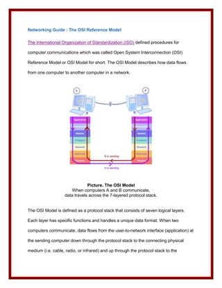
Picture. The OSI Model
When computers A and B communicate,
data travels across the 7-layered protocol stack.
The OSI Model is defined as a protocol stack that consists of seven logical layers.
Each layer has specific functions and handles a unique data format. When two
computers communicate, data flows from the user-to-network interface (application) at
the sending computer down through the protocol stack to the connecting physical
medium (i.e. cable, radio, or infrared) and up through the protocol stack to the
2. network-to-user interface (application) at the receiving computer. When data flows
from an upper layer to a lower layer, it is converted to the lower layer data format and
a lower layer header is added to it. This process is called encapsulation. Conversely,
when data flows from a lower layer to an upper layer, it is converted to the upper layer
data format and the lower layer header is discarded.
Networking Guide : The OSI Reference Model
Even though most computer network technologies do not follow strictly to the OSI
Model in that they combine several OSI layers functions in one protocol, the OSI
Model is still used as a reference and a guideline in network design. Understanding
the OSI Model will help you understand how a network works. The OSI Model protocol
stack is explained in the following table:
Layer Layer Name Functions Examples
Application HTTP, FTP, Telnet, SMTP,
Layer 7 application support
Layer SNMP, POP3, IMAP4
data format conversion,
Presentation
Layer 6 data compression, and
Layer
encryption
Layer 5 Session user identification; SIP
3. Layer establishing,
maintaining, and
terminating a session
Transport
Layer 4 end-to-end transport TCP, UDP, RTP, RTCP
Layer
Network IP, IPSec, IPX, NetBEUI,
Layer 3 addressing, routing
Layer AppleTalk, ICMP
Ethernet, Wi-Fi, HomePNA,
medium access
Data Link HomePlug, PPP, PPTP,
Layer 2 control, error detection,
Layer L2TP, ATM, Frame Relay,
retransmission
Token Ring, FDDI
electrical/optical
RF, UTP, STP, coax, fiber
Physical signaling, cabling,
Layer 1 optic, connectors,
Layer connector pin
signaling, voltages
assignment
Due to its complex functions, the Data Link Layer is divided into two sublayers, that
isMedia Access Control (MAC)sublayer and Logical Link Control (LLC)sublayer. MAC
sublayer is the lower part, closer to the Physical Layer. MAC sublayer controls access
to the physical medium. LLC sublayer is the upper part that interfaces with the
Network Layer.
4. Session Layer, Presentation Layer, and Application Layer are often referred to as
Upper Layers. These layers basically handle user connection and data formatting. In
most network technologies, such as TCP/IP, the differences between the three layers
are blurred and their functions are often handled by one protocol.
Physical Layer, Data Link Layer, Network Layer, and Transport Layer are referred to
as Lower Layers. The lower layers generally concern with how data is transported
across the network.
Networking Guide : Physical Media - Twisted Pair Cable
A network needs physical medium to connect its nodes together. The physical medium
is where the data actually flows. There are several media types often used in
networking. They are described in the following paragraphs.
Picture: Twisted Pair
Twisted pairis two insulated copper wires that are twisted around each other to
minimize interference and noise from other wires. Based on the presence of individual
shield and overall (outer) shield, there are three types of twisted pair, i.e. UTP, STP,
and ScTP. Individual shield encloses a single twisted pair, while outer shield encloses
all twisted pairs in a cable. A shield is a protective sheath that is made from conductive
material (metal) and functions to protect the twisted pair from external interference. An
insulator is made from non-conductive material, such as plastic.
5. Picture: Unshielded Twisted Pair (UTP)
UTP (Unshielded Twisted Pair)is a cable containing several twisted pairs that is only
insulated but not shielded. UTP is the most widely used cable in telephone and
computer networks because it is relatively cheaper than other cables and performs
well in normal electrical environment such as inside an office or a house.
Networking Guide : Physical Media - Twisted Pair Cable Categories
Picture: Shielded Twisted Pair (STP)
STP (Shielded Twisted Pair)is a cable containing several twisted pairs that has
individual shields, an outer shield, and an insulator. STP is more reliable than UTP.
However STP is less known because it is used only in situation where there is
complex cabling such as in factory building.
6. Picture: Screened Twisted Pair (ScTP)
ScTP (Screened Twisted Pair) is similar with STP but each twisted pair has no
individual shield.
Twisted pair cable is graded based on the number of twists per inch, its cable structure
and traffic carrying capacity into several categories, as follows:
Category Type Bandwidth Typical applications
Cat 1 UTP < 1 MHz telephone
Cat 2 UTP 1 MHz telephone
UTP,
telephone, 10BaseT, 4 Mbps Token
Cat 3 ScTP, 16 MHz
Ring
STP
UTP,
Cat 4 ScTP, 20 MHz 16 Mbps Token Ring, 10BaseT
STP
UTP,
Cat 5 100 MHz 10BaseT, 100BaseT
ScTP,
7. STP
UTP,
Cat 5e ScTP, 350 MHz 100BaseT, 1000BaseT
STP
UTP,
Cat 6 ScTP, 550 MHz 1000BaseT, ATM
STP
ScTP,
Cat 7 600 MHz 10 Gbps network
STP
Table: Twisted Pair categories and their applications
Networking Guide : Physical Media - Coaxial Cable
Picture: Coaxial cable (coax) structure
Coaxial cable contains a solid or stranded wire in the core that is insulated with a
dielectric layer, then protected with a solid or braided metallic shield, and covered with
an outer insulator. Electromagnetic wave propagation in a coaxial cable is confined
within the space between the core and the outer conductors. The structure of a coaxial
cable makes it less susceptible to interference, noise, and crosstalk than the twisted
8. pair cable.
Coaxial cable is often classified based on its characteristic impedance. Most coaxial
cables have characteristic impedance of 50 or 75 Ohms. Coaxial cables in the market
are usually named with RG prefix which may stand for Radio Grade. Each RG type is
related with certain characteristic impedance and outer diameter. For example RG-6
which has impedance of 75 Ohms is used for connecting cable modem or TV to a
CATV network. RG-58 (50 Ohms) is used in earlier Ethernet networks (10Base2).
Coaxial cable is terminated with RF (BNC) connectors.
Networking Guide : Physical Media - Fiber Optic
Picture: Fiber optic structure
Fiber Optic (optical fiber) is a thin glass or plastic strand in the core which is
surrounded by a cladding and a protective coat and is used to carry information in
optical (light) pulses. Because in fiber optic, information is transmitted in optical pulses
instead of electrical signals, fiber optic is not affected by EMI (electromagnetic
interference) and RFI (radio frequency interference). Moreover, fiber optic has very
large bandwidth which is limited only by the equipment that lights the fiber (i.e.
SDH/SONET, ATM, DWDM). But fiber optic is more expensive than twisted pair, coax
and radio.
9. Picture: single-mode fiber (left) and multimode fiber (right)
Fiber optic is often classified into single-mode and multimode. In a single-mode fiber,
light travels in one path (mode). In a multimode fiber, light travels in multiple paths
(multimode). Single mode fiber can reach longer distance than multimode fiber, so it is
mostly used for MAN or WAN. While multimode fiber is suitable for implementing high
speed LAN.
Because of its reliability and wider bandwidth, fiber optic is often used in backbone
networks where cables run in ducts and in broadband networks that deliver bandwidth
intensive applications, such as HDTV, video streaming, video conferencing and Video
on Demand.
Networking Guide : Network Components
Repeater
Repeater receives signal from a transmitter, amplifies it, and retransmits it to a
receiver. A repeater is put in a network to extend the network to a longer distance or a
greater area. There can be more than one repeater between a transmitter and a
receiver, however the number of repeaters is not unlimited, because additional
repeaters may introduce more interference or noise.
10. Picture: Repeater
A repeater extends the reach of transceivers 1 and 2.
Note: Transceiver is transmitter and receiver.
Repeater is also known as regenerator. Some vendors name it range expander or line
(cable) extender.
Bridge
When you have two or more networks with different layer 2 protocols, such as
Ethernet, HomePNA, HomePlug, and wireless LAN (Wi-Fi) you can connect the
networks using a bridge. Bridge is also used to split a network into separate segments.
This is intended to filter traffic and create an efficient network.
Picture: Bridge
A network bridge enables communication between two computers at different
networks.
A bridge function can be handled by a software application. In Windows XP, when you
install two or more network adapters, a Network Bridge is automatically created for
you. A Network Bridge icon will appear in the Network Connections folder. However in
Windows XP Service Pack 2 (SP2), a Network Bridge will be created only after user
confirmation. This behavior is in line with SP2 main goal, that's to improve computer
11. and network security.
ing Guide : Network Components
Hub
Hub is the central connection point in a network. Hub is used in a network that uses
star topology. A sending computer transmits its signal to a hub, the hub then
retransmits the signal to all other computers. A passive hub functions as a relay
station that receives and retransmits signal. An active hub functions as a repeater that
regenerates signal before retransmitting.
Picture: Hub
When A sends to C, the Hub receives signal from A and retransmits it to both B and C.
Only C then processes the signal.
Using a hub, the network bandwidth (capacity) is shared by all available computers,
therefore each computer only uses a portion of bandwidth. That's why hub is mostly
used in small networks where there are only a few connected devices or computers.
However, hub is not required if there are only two computers in a network. In that
case, a direct connection using cable or wireless link can be used to connect both
computers.
Switch
12. Like hub, switch works as the central connection point in a network. However when a
switch receives a packet from a sending computer, it examines the destination
address (i.e. MAC address of the destination computer) from the packet header and
retransmits the packet to the destination computer only. That's possible because a
switch maintains a table that maps all its ports with all connected devices' MAC
addresses.
Picture: Switch
When A sends to C, the Switch receives signal from A and only retransmits it to C.
B doesn't receive the signal.
Using a switch, the whole bandwidth can be used by each connected computer. That's
why most big networks in which a large amount of data must be transferred at any
given time, use a switch instead of hub. Switch is not always a separate device, it is
very often integrated with router.
Gateway
Gateway functions to connect two completely different networks. It performs protocol
translation. Although gateway is considered a Layer 7 device in many publications, it
actually works across the seven layers of the OSI Model. In Internet Telephony, a
13. gateway connects the VoIP network to the PSTN.
Picture: Gateway
VoIP/PSTN Gateway performs protocols and signaling translation,
so a VoIP-enabled phone or PC can communicate with a regular phone.
Networking Guide : Network Components - Summary
The following table explains network components along with their functions and
the corresponding layers in the OSI Model. Click each component name for a
more detailed explanation.
Network
Functions OSI Model
Component
converts a computer message into
Network
electrical/optical signals for Physical (Layer 1)
Adapter
transmission across a network.
puts a message (baseband signal) on
Modem
a carrier for efficient transmission;
(Modulator Physical (Layer 1)
takes the baseband signal from the
demodulator)
carrier.
14. Repeater receives signal, amplifies it, then
Physical (Layer 1)
(Regenerator) retransmits it.
connects networks with different
Data Link (Layer
Bridge Layer 2 protocols; divides a network
2)
into several segments to filter traffic.
connects computers in a network;
receives a packet from a sending
Hub Physical (Layer 1)
computer and transmits it to all other
computers.
connects computers in a network;
receives a packet from a sending Data Link (Layer
Switch
computer and transmits it only to its 2)
destination.
connects computers in a wireless
network; connects the wireless Data Link (Layer
Access Point
network to wired networks; connects 2)
it to the Internet.
forwards a packet to its destination
Router by examining the packet destination Network (Layer 3)
network address.
Residential connects a home network to the Network (Layer 3)
15. Gateway Internet; hides all computers in the
home network from the Internet.
connects two totally different
Gateway networks; translates one All layers
signaling/protocol into another.
Networking Guide : Architecture
Network architecture describes the relation among nodes in a network.
A client-servernetwork has a node that functions as a server which provides
resources (e.g. programs, disk, printers) for other nodes (client computers) and
manages clients access to the network resources. Corporate networks are typically
client-server with one or more servers that store corporate information and employees'
computers as clients.
16. Picture: Client-Server Network
Client computers access programs or information provided by the servers.
A peer-to-peer network does not have a server, each node (computer) in the network
can share its own resources with other nodes and determines other nodes access
levels to its own resources. Home networks are typically peer-to-peer. A peer-to-peer
network is also called a workgroup.
Picture: Peer-to-Peer Network