1. ELM323
OBD (ISO) to RS232 Interpreter
Description Features
Since the 1996 model year, North American • Low power CMOS design
automobiles have been required to provide an OBD
• Crystal controlled for accuracy
(On Board Diagnostics) data port for the connection
of test equipment. This port is used to obtain • ISO 9141-2 and ISO 14230-4 protocols
emissions-related diagnostics information, and in
• Configurable with AT commands
some cases can also be used to obtain real-time
vehicle operating parameters. • Standard ASCII character output
The ELM323 is a 14 pin integrated circuit that, • Four high current LED drive outputs
with only a few external components, is able to
convert between the OBD data format and the
standard RS232 serial data format. This allows
virtually any personal computer or PDA to
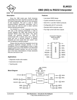
Connection Diagram
communicate with a vehicle using only a standard
PDIP and SOIC
serial port and a terminal program. If desired, (top view)
hobbyists can even create their own custom ‘scan
tool’ by adding an interface program.
Please note that while this integrated circuit has VDD 1 14 VSS
undergone significant changes recently, it is still
XT1 2 13 OBDK
considered to be an experimenter’s circuit. It does
support a great many of the ISO9141 and ISO14230 XT2 3 12 OBDL
(KWP2000) protocol vehicles, but not all of them,
LFmode 4 11 OBDIn
due to the many interpretations of these standards
that are to be found in use. RS232Rx 5 10 OBDTx
RS232Tx 6 9 OBDRx
Applications RSRx 7 8 RSTx
• Diagnostic trouble code readers
• Automotive scan tools
• Teaching aids
3.58 MHz
Block Diagram XT1 2 3 XT2
Timing and
LFmode 4 Control
13 OBDK
RS232 OBD 12 OBDL
RS232Rx 5 Interface Interface
Interpreter
11 OBDIn
RS232Tx 6
RSRx 7 10 OBDTx
RSTx 8 9 OBDRx
ELM323DSD Elm Electronics – Circuits for the Hobbyist 1 of 19
< http://www.elmelectronics.com/ >
2. ELM323
Pin Descriptions
VDD (pin 1) RS232Tx (pin 6)
This pin is the positive supply pin, and should always This is the RS232 transmit or data output pin. The
be the most positive point in the circuit. Internal signal level is compatible with most interface ICs,
circuitry connected to this pin is used to provide and there is sufficient current drive to allow
power on reset of the microprocessor, so an external interfacing using only a PNP transistor, if desired.
reset signal is not required. Refer to the Electrical
Characteristics section for further information. LED Drive Outputs (pins 7, 8, 9, and 10)
These four pins are driven to low levels when the
XT1 (pin 2) and XT2 (pin 3) ELM323 is transmitting or receiving RS232 or OBD
A 3.579545 MHz NTSC television colourburst crystal data. Otherwise, they are at a high level. Current
is connected between these two pins. Crystal capability is suitable for directly driving most LEDs
loading capacitors (typically 27pF) will also normally through current limiting resistors. If unused, these
be connected between each of these pins and the pins should be left open-circuited.
circuit common (Vss).
OBDIn (pin11)
LFmode (pin 4) The OBD data is input to this pin, with a high logic
This input is used to select the default linefeed mode level representing the active state of the OBD K line.
after a power-up or system reset. If it is at a high No Schmitt trigger input is provided, so the OBD
level, then by default messages sent by the ELM323 signal should be buffered to minimize transition
will be terminated with both a carriage return and a times for the internal CMOS circuitry.
linefeed character. If it is at a low level, lines will be
terminated by a carriage return only. This behavior OBDL (pin 12) and OBDK (pin 13)
can always be modified by issuing AT L0 or AT L1 These are the active high output signals which are
commands (see the section on AT Commands). used to drive the OBD bus, using external NPN
transistors. Data transfer normally occurs only by the
RS232Rx (pin5) K line, but the standards require that the L line be
A computer’s RS232 transmit signal can be directly implemented as well in order to properly initialize the
connected to this pin from the RS232 line as long as bus. See the Example Applications section for more
a current limiting resistor (typically about 47KΩ) is details.
installed in series. (Internal protection diodes will
pass the resistor current safely to the supply VSS (pin 14)
connections, protecting the ELM323.) Internal signal Circuit common is connected to this pin. This is the
inversion and Schmitt trigger waveshaping provide most negative point in the circuit.
the necessary signal conditioning.
Ordering Information
These integrated circuits are available in either the 300 mil plastic DIP format, or in the 150 mil SOIC surface mount
type of package. To order, add the appropriate suffix to the part number:
300 mil Plastic DIP...................................ELM323P 150 mil SOIC........................................ ELM323SM
All rights reserved. Copyright 2001 to 2009 by Elm Electronics Inc.
Every effort is made to verify the accuracy of information provided in this document, but no representation or warranty can be
given and no liability assumed by Elm Electronics with respect to the accuracy and/or use of any products or information
described in this document. Elm Electronics will not be responsible for any patent infringements arising from the use of these
products or information, and does not authorize or warrant the use of any Elm Electronics product in life support devices and/or
systems. Elm Electronics reserves the right to make changes to the device(s) described in this document in order to improve
reliability, function, or design.
ELM323DSD Elm Electronics – Circuits for the Hobbyist 2 of 19
< http://www.elmelectronics.com/ >
3. ELM323
Absolute Maximum Ratings
Storage Temperature....................... -65°C to +150°C Note:
Ambient Temperature with Stresses beyond those listed here will likely damage
Power Applied....................................-40°C to +85°C the device. These values are given as a design
guideline only. The ability to operate to these levels
Voltage on VDD with respect to VSS............ 0 to +7.0V is neither inferred nor recommended.
Voltage on any other pin with
respect to VSS........................... -0.6V to (VDD + 0.6V)
Electrical Characteristics
All values are for operation at 25°C and a 5V supply, unless otherwise noted. For further information, refer to note 1 below.
Characteristic Minimum Typical Maximum Units Conditions
Supply voltage, VDD 4.5 5.0 5.5 V
VDD rate of rise 0.05 V/ms see note 2
Average supply current, IDD 1.0 2.4 mA see note 3
Input low voltage VSS 0.15 x VDD V
Input high voltage 0.85 x VDD VDD V
Output low voltage 0.6 V Current (sink) = 8.7mA
Output high voltage VDD - 0.7 V Current (source) = 5.4mA
RS232Rx pin input current -0.5 +0.5 mA see note 4
RS232 baud rate 9600 baud see note 5
Notes:
1. This integrated circuit is produced with a Microchip Technology Inc.’s PIC16C505 as the core embedded
microcontroller. For further device specifications, and possibly clarification of those given, please refer to the
appropriate Microchip documentation (available at http://www.microchip.com/).
2. This spec must be met in order to ensure that a correct power on reset occurs. It is quite easily achieved
using most common types of supplies, but may be violated if one uses a slowly varying supply voltage, as
may be obtained through direct connection to solar cells, or some charge pump circuits.
3. Device only. Does not include any load currents.
4. This specification represents the current flowing through the protection diodes when applying large voltages
to the RS232Rx input (pin 5) through a current limiting resistance. Currents quoted are the maximum that
should be allowed to flow continuously.
5. Nominal data transfer rate when the recommended 3.58 MHz crystal is used as the frequency reference.
Data is transferred to and from the ELM323 with 8 data bits, no parity, and 1 stop bit (8 N 1).
ELM323DSD Elm Electronics – Circuits for the Hobbyist 3 of 19
< http://www.elmelectronics.com/ >
4. ELM323
Overview
The following describes how to use the ELM323 to programmable features of this product as well.
obtain a great deal of information from your vehicle. To Using the ELM323 is not as daunting as it first
some, the following information will be overwhelming, seems. Many users will never need to issue an ‘AT’
and for others it will not be nearly enough. command, adjust timeouts or change the headers. For
We begin by discussing just how to talk to the IC most, all that is required is a PC or a PDA with a
using a PC, then go on to explain how to change terminal program (such as HyperTerminal or ZTerm),
options using ‘AT’ commands, and finally go on to and knowledge of one or two OBD commands, which
actually use the ELM323 to obtain trouble codes (and we provide in the following…
reset them). For the more advanced experimenters,
there are also sections on how to use some of the
Communicating with the ELM323
The ELM323 relies on a standard RS232 type must be terminated with a carriage return character
serial connection to communicate with the user. The (hex ‘0D’) before it will be acted upon. The one
data rate is fixed at 9600 baud, with 8 data bits, no exception is when an incomplete string is sent and no
parity bit, 1 stop bit, and no handshaking (often carriage return appears. In this case, an internal timer
referred to as 9600 8N1). All responses from the IC will automatically abort the incomplete message after
are terminated with a single carriage return character about 15 seconds, and the ELM323 will print a single
and, optionally, a linefeed character. Make sure your question mark (‘?’) to show that the input was not
software is configured properly for the mode you have understood (and was not acted upon).
chosen. Messages that are not understood by the ELM323
Properly connected and powered, the ELM323 will (syntax errors) will always be signalled by a single
energize the four LED outputs in sequence (as a ‘lamp question mark. These include incomplete messages,
test’) and will then send the message: incorrect AT commands, or invalid hexadecimal digit
ELM323 v2.0 strings, but are not an indication of whether or not the
message was understood by the vehicle. One must
>
keep in mind that the ELM323 is a protocol interpreter
In addition to identifying the version of this IC, that makes no attempt to assess the OBD messages
receiving this string is a good way to confirm that the for validity – it only ensures that an even number of
computer connections and terminal software settings hex digits were received, combined into bytes, and
are correct. However, at this point no communications sent out the OBD port, and it does not know if the
have taken place with the vehicle, so the state of that message sent to the vehicle is in error.
connection is still unknown. Incomplete or misunderstood messages can also
The ‘>’ character displayed above is the ELM323’s occur if the controlling computer attempts to write to
prompt character. It indicates that the device is in its the ELM323 before it is ready to accept the next
idle state, ready to receive characters on the RS232 command (as there are no handshaking signals to
port. Messages sent from the computer can either be control the data flow). To avoid a data overrun, users
intended for the ELM323’s internal use, or for should always wait for the prompt character (‘>’)
reformatting and passing on to the OBD bus. before issuing the next command.
The ELM323 can quickly determine where the Finally, there are a few convenience items to note.
received characters are to be directed by analyzing the The ELM323 is not case-sensitive, so ‘ATZ’ is
entire string once the complete message has been equivalent to ‘atz’, and to ‘AtZ’. Also, it ignores space
received. Commands for the ELM323’s internal use characters and all control characters (tab, linefeed,
will always begin with the characters ‘AT’ (as is etc.) in the input, so they can be inserted anywhere to
common with modems), while commands for the OBD improve readability. Another feature is that sending
bus are only allowed to contain the ASCII codes for only a single carriage return character will always
hexadecimal digits (0 to 9 and A to F). repeat the last command (making it easier to request
Whether an ‘AT’ type internal command or a hex updates on dynamic data such as engine rpm).
string for the OBD bus, all messages to the ELM323
ELM323DSD Elm Electronics – Circuits for the Hobbyist 4 of 19
< http://www.elmelectronics.com/ >
5. ELM323
AT Commands
Several parameters within the ELM323 can be command, so the user knows that it has been
adjusted in order to modify its behaviour. These do not executed.
normally have to be changed before attempting to talk Some of the following commands allow passing
to the vehicle, but occasionally the user may wish to numbers as arguments in order to set the internal
customize the settings; for example by turning the values. These will always be hexadecimal numbers
character echo off, adjusting a timeout value, or which must be provided in pairs. The hexadecimal
changing the header bytes. In order to do this, internal conversion chart in the OBD Commands section may
‘AT’ commands must be issued. prove useful if you wish to interpret the values. Also,
Those familiar with PC modems will immediately one should be aware that for the on/off types of
recognize AT commands as a standard way in which commands, the second character is a number (1 or 0),
modems are internally configured. The ELM323 uses the universal terms for on and off respectively.
essentially the same method, always watching the The following is a summary of all of the AT
data sent by the PC, looking for messages that begin commands that are recognized by the current version
with the character ‘A’ followed by the character ‘T’. If of the ELM323, listed alphabetically. Users of previous
found, the next characters will be interpreted as versions of this product (v1.x) should note that their
internal configuration or ‘AT’ commands, and will be ICs will not support all of the functions shown.
executed upon receipt of a terminating carriage return
character. The ELM323 will usually reply with the
characters ‘OK’ on the successful completion of a
AR [ Automatically set the Receive address ] received on the OBD connection. This command
Responses from the vehicle will be acknowledged shows the entire OBD buffer contents as a length byte
and displayed by the ELM323, if its internally stored followed by 11 data bytes. Since not all of the data
receive address matches the address that the bytes are likely to be relevant, be sure to check the
message is being sent to. With the Auto Receive mode value contained in the length byte before interpreting
in effect, the value used for the receive address will be the data. The format of the data returned by this
chosen based on the current header bytes, and will command will follow the data mode in effect at the time
automatically be updated whenever the header bytes (Packed Data or Formatted Data) so you may want to
are changed. adjust that before viewing the data.
The value that is used for the receive address is
determined based on several factors. If the IC is D [ set all to Defaults ]
connected to a KWP2000 (ISO14230) system, the
third byte of the header will always be used as the This command is used to set all of the options to
receive address. If the IC is connected to an ISO9141 their default or ‘factory’ settings, as listed in these
system, the receive address will depend on the pages. This lets you experiment with different settings,
contents of the first header byte. If the first byte shows but be able to quickly restore them all to the original
that the message uses physical addressing, the third settings using only one command.
byte of the header will be used for the address, To summarize the changes, E will be on, H will be
otherwise (for functional addressing) the second off, and L will be set according to the level at pin 4.
header byte, increased in value by 1, will be used. The Auto Receive mode (AR) will be selected, data will
Auto Receive is turned on by default. be transmitted in the standard formatted way (as if
chosen by FD), and both the ‘NO DATA’ timeout and
the period between bus idle (wakeup) messages will
BD [ OBD receive Buffer Dump ] be reset to their default values. As well, the header
There may be times when a bus initialization is not bytes will be set to the prescribed values for OBDII
successful, or perhaps the OBDRx LED flickers but operation, and the receive address will be adjusted
nothing is sent on the RS232 connection. In these accordingly. If the bus had been initiated, it will remain
cases, it may be an advantage to see just what was active.
ELM323DSD Elm Electronics – Circuits for the Hobbyist 5 of 19
< http://www.elmelectronics.com/ >
6. ELM323
AT Commands (continued)
E0 and E1 [ Echo off (0) or on(1) ] L0 and L1 [ Linefeeds off (0) or on(1) ]
These commands control whether or not Whether or not the ELM323 transmits a linefeed
characters received on the RS232 port are character after each carriage return character is
retransmitted (or echoed) back to the host computer. controlled by this option. If an ATL1 is issued, linefeed
To reduce traffic on the RS232 bus, users may wish to generation will be turned on, and for AT L0, it will be
turn echoing off by issuing ATE0. The default is E1 off. Users may wish to have this option on if using a
(echo on). terminal program, but off if using a custom interface
(as the extra characters transmitted will only serve to
slow the vehicle polling down). The default setting is
FD [ send Formatted Data ]
determined by the level at pin 4 when the IC is reset
This command requests that all of the vehicle’s (power-on or AT Z), or when the default values are
responses be returned as standard ASCII characters restored (AT D).
(which are readable with virtually all terminal
programs). Byte values are sent as a pair of ASCII
MA [ Monitor All messages ]
characters, each representing a hexadecimal digit,
with a space character sent between each pair as a Using this command places the ELM323 into a
separator. Every line will end with a carriage return bus monitoring mode, in which it displays all messages
character and (optionally) a linefeed character, as it sees them on the OBD bus. This continues
ensuring that each response appears on a new line. indefinitely until stopped by activity on the RS232
This is the default output mode. input. To stop the monitoring, one should send any
single character then wait for the ELM323 to respond
with a prompt character (‘>’). Waiting for the prompt is
FI [ perform a Fast bus Init ]
necessary as the response time is unpredictable,
Issuing this command forces the ELM323 to varying depending on what the IC was doing when
perform a fast (KWP / ISO14230) bus initialization interrupted. If, for instance, it was in the middle of
sequence, regardless of the present state of the bus. printing a line, it will first complete the line then return
Note that the bus does not need to be manually to the command state, then issue the prompt
initalized with this command, as it will be performed character. If the ELM323 was simply waiting for OBD
automatically by the ELM323 when required. (It will input, it would return immediately. The character which
first try a slow initialization, and if it is not successful, it stops the monitoring will always be discarded, and will
will then attempt a fast initialization sequence.) not affect subsequent commands.
This command has been provided as a
convenience, and should be used with caution. No
H0 and H1 [ Headers off (0) or on(1) ]
periodic ‘wakeup’ messages are sent by the ELM323
These commands control whether or not the while monitoring the bus in this mode, so if the bus
header information is shown in the responses. All OBD had been initialized before this command was invoked,
messages have an initial (header) string of three bytes the vehicle connection will likely ‘go to sleep’ and will
and a trailing check digit, which are normally not have to be re-initialized. The ELM323 will not be aware
displayed by the ELM323. To see this extra that the connection was lost, however, and will likely
information, users can turn the headers on by issuing have to be reset with an AT SW 00, or an AT Z
an ATH1. The default is H0 (headers off). command.
I [ Identify yourself ] PD [ send Packed Data ]
Issuing this command causes the chip to identify This option is for those that are building a
itself, by printing the startup product ID string (this is computer interface and want the fastest data transfer
currently ‘ELM323 v2.0’). Software can use this to rate possible while still operating at 9600 baud. When
determine exactly which version of the integrated selected, all of the data obtained from the vehicle will
circuit it is connected to, without having to reset the IC. be sent as a single length byte, followed by the actual
ELM323DSD Elm Electronics – Circuits for the Hobbyist 6 of 19
< http://www.elmelectronics.com/ >
7. ELM323
AT Commands (continued)
response bytes that were received from the vehicle. SI [ perform a Slow bus Init ]
There will be no added space characters, and no
Issuing this command forces the ELM323 to
trailing carriage returns or linefeed characters inserted
perform a slow (5 baud) bus initialization sequence,
between messages. This provides a very compact
regardless of the present state of the bus. Note that
format for data transfer.
the bus does not have to be manually initialized with
Note that the length byte only represents the total
this command. If it is not active when a command is
number of data bytes following, and does not include
issued to the vehicle, the ELM323 will automatically try
itself. Also, if there was a data (checksum) error, this
a slow initialization, and if that is not successful, will
length byte will have its most significant bit set, making
then attempt a fast initialization.
it appear that the length is greater than 128. If you
ignore the most significant bit (or subtract 128 from the
value), the other 7 bits will still provide a valid byte SR hh [ Set the Receive address to hh ]
count for the remainder of the message.
Depending on the application, users may wish to
When the vehicle does not provide a response to
manually set the address for which the ELM323 will
a query (a ‘NO DATA’ condition), the response has no
display responses. Issuing this command will turn off
data bytes, but still sends a length byte with value ‘0’.
the AR mode, and force the IC to only accept
responses from the vehicle that are addressed to hh,
SH xx yy zz [ Set the Header to xx yy zz ] ignoring all others.
This command allows the user to control the
values that are sent as the three initial (header) bytes ST hh [ Set Timeout to hh ]
in each message. The value of hex digits xx will be
After sending a request, the ELM323 waits a
used for the first or priority/type byte, yy will be used
preset time before declaring that there was no
for the second or target byte, and zz will be used for
response from the vehicle (the ‘NO DATA’ response).
the third or source byte. These values will remain in
Depending on the application (and priority of the
effect until set again, or until restored to the default
request), users may want to modify this timeout period
values with the AT D, or AT Z commands.
to allow more or less time. The ST command is used
For ISO9141 vehicles, the default header values
to do that.
are 68 6A F1, while for ISO14230 (KWP2000), they
The actual time allowed before a timeout occurs is
are Cn 33 F1, where n represents the number of data
(approximately) 4 ms x the byte value passed as the
bytes in the message. Note that when assigning
hexadecimal argument. Passing a value of FF thus
header bytes for ISO14230 systems, whatever value
results in a maximum time of about 1020 ms. Note that
you provide for ‘n’ will be ignored by the ELM323, and
a setting of 00 (zero) is not allowed, and will be
the appropriate value will automatically be calculated
replaced internally with the default setting value – hex
and inserted just before sending each message.
32 (decimal 50) resulting in a timeout value of
A feature has been added to this version of the IC
200 milliseconds.
to allow experimenting with the header bytes, while not
affecting the periodic ‘wakeup’ messages. That is, a
separate set of header bytes can be used for the SW hh [ Set Wakeup to hh ]
periodic wakeup messages and for those used by the
Once a data connection is made with a vehicle,
standard requests. This is accomplished by first
there needs to be data flow every few seconds, or the
assigning header bytes (or leaving them as the default
connection will ‘go to sleep’. The ELM323 will
ones) then initializing the OBD bus. Whatever header
automatically generate ‘wakeup’ messages in order to
bytes are being used when the bus is initialized will be
maintain this connection whenever the user is not
‘locked in’ at that point and used for all of the periodic
requesting any data. (The responses from these
messages until the IC is reset (or the AT SW 00 is
messages are always ignored, and not seen by the
used to turn them off). Issuing the AT SH command
user.)
after the bus has been initialized will only affect the
The time between these periodic ‘wakeup’
requests that follow, and will have no effect on any of
messages can be adjusted in 20 msec increments
the periodic wakeup messages.
using the AT SW hh command, where hh is any
ELM323DSD Elm Electronics – Circuits for the Hobbyist 7 of 19
< http://www.elmelectronics.com/ >
8. ELM323
AT Commands Summary
hexadecimal value from 00 to FF. The maximum
possible time delay of 5.10 seconds thus occurs when
a value of FF (or decimal 255) is used. The default
setting is 7D (or decimal 125) which provides a
nominal delay of 2.5 seconds between messages.
Note that the value 00 (zero) is treated as a very
special case, and must be used with caution. It is used
to stop all periodic messages, by telling the ELM323
internally that the bus is no longer active. This can be
convenient if the vehicle has timed out (perhaps when
using the AT MA command) and you wish to inform ELM323 AT Commands
the ELM323 of that without performing a full reset. general
Issuing AT SW 00 will not change the previous setting
D set all to Defaults
for the time between wakeup messages.
Attempting to communicate with the vehicle after I show the ID string
issuing AT SW 00 will result in the ELM323 perfoming Z reset all
a bus initialization sequence. <CR> repeat last command
bus control
Z [ reset all ] FI Fast Init
This command causes the chip to perform a SI Slow Init
complete reset as if power were cycled off and then on SW hh Set Wake (hh*20ms)
again. All settings are returned to their default values,
and the chip will be put in the idle state, waiting for responses
characters on the RS232 bus. E1/0 Echo on/off
H1/0 Headers on/off
L1/0 Linefeeds on/off
Figure 1 shows all of the current ELM323 AT FD use Formatted Data
commands in one convenient chart. In order to help PD use Packed Data
with the understanding of these, we have grouped the ST hh Set Timeout (hh*4ms)
commands into four functional areas, but this has no
bearing on how they need to be used – it is only for requests
clarity. You may find this chart to be useful when BD Buffer Dump
experimenting with the IC. MA Monitor All
SH xx yy zz Set Header
AR Auto Receive
SR hh Set Rx address
Figure 1. ELM323 Command Summary
ELM323DSD Elm Electronics – Circuits for the Hobbyist 8 of 19
< http://www.elmelectronics.com/ >
9. ELM323
Bus Initiation
Both the ISO 9141-2 and ISO 14230-4 (KWP2000)
standards require that the vehicle’s OBD bus be
initialized before any communications can take place.
The ISO 9141 standard allows for only a slow (2 to 3
second) process, while ISO 14230 allows for both the
slow method, and a faster alternative. In either case, need to initialize
once the bus has been initiated, communications must the bus
take place at least once every five seconds, or the bus
will revert to a low-power ‘sleep’ mode.
The ELM323 takes care of this bus initiation and
the periodic sending of ‘keep-alive’ or ‘wakeup’
Try a slow init
messages for you – it is automatic and requires no
input from the user. The ELM323 will not perform the
bus initiation until the first message needs to be sent,
however, and it will do so by first attempting the slow
method, and if that fails then trying the fast. During the any
automatic initiation process, the following message will response
be displayed: yes ?
BUS INIT: ...
no
with the three dots appearing as the slow initiation
process is carried out. This will be followed by either KWP
no
the expression ‘OK’ to say it was successful, or else or Try a fast init
an error message to indicate that there was a problem. ISO
(The most common error encountered is in forgetting ?
to turn the vehicle’s key to ‘ON’ before attempting to
talk to the vehicle.)
Once initiated, the ELM323 does what is required yes any
yes
to keep the bus alive, without any intervention from the response
user. If you have installed monitoring LEDs, you will be ?
able to see that automatic messages are being sent
every few seconds in order to create bus activity.
no
If the user does not wish to use the two step Lock/set the
automatic bus initiation process, they can specify that keep-alive headers
only the Slow Initiation, or only the Fast Initiation, be print ERROR
attempted, by issuing the commands AT SI or AT FI
respectively. Note that the three dots are only printed
during a slow initiation, so if AT FI is issued, they will print OK
not appear.
The chart at the right shows the automatic bus
initiation process in more detail:
Bus is alive so
resume activities
Figure 2. Initializing the Bus
ELM323DSD Elm Electronics – Circuits for the Hobbyist 9 of 19
< http://www.elmelectronics.com/ >
10. ELM323
OBD Commands
If the bytes received on the RS232 bus do not would be sent to the ELM323 by way of the RS232
begin with the letters ‘A’ and ‘T’, they are assumed to port. The ELM323 would store the characters as they
be OBD commands for the vehicle. Each pair of ASCII are received, and when the third character (the
bytes will be tested to ensure that they are valid carriage return) was received, would begin to assess
hexadecimal digits, and will then be combined into the other two. It would see that they are both valid hex
single data bytes for transmitting to the vehicle. digits, and would convert them to a one byte value
OBD commands are actually sent to the vehicle (decimal value is 166). Three header bytes and a
embedded in a data packet. The standards require checksum byte would be added, and a total of five
that three header bytes and an error checksum byte bytes would be sent to the vehicle. Note that the
be included with every message, and the ELM323 carriage return character is only a signal to the
adds these extra bytes to your command bytes ELM323, and is not sent on to the vehicle.
automatically. The initial (default) values for these After sending the command, the ELM323 listens
header bytes are usually adequate for most requests, on the OBD bus for messages, looking for ones that
but if you wish to change them, there is a method to do are directed to it. If a message address matches,
so (see the Advanced Data Retrieval section). those received bytes will be sent on the RS232 port to
When receiving data from a vehicle, the extra the user, while messages received that do not have
header bytes are not normally displayed by the matching addresses will be ignored (but still available
ELM323. Occasionally vehicles will have more than for viewing with the AT BD command).
one module responding to a request, though, and it The ELM323 will continue to wait for messages
may be useful to see the extra header bytes in order to addressed to it until there are none found in the time
determine which ECU module responded. (The third that was set by the AT ST command. As long as
byte of the response is the address of the sender). To messages are received, the ELM323 will continue to
view these extra header bytes, simply issue an AT H1 reset this timer. Note that the IC will always respond
internal command, to turn the header printing on. with something, even if it is to say ‘NO DATA’,
Most OBD commands are only one or two bytes in (meaning that there were no messages at all
length, but some can be three or more bytes long. The addressed to it).
ELM323 is capable of sending as many as seven data
bytes (14 hexadecimal digits), the maximum number
allowed by the standards. Attempts to send either an Hexadecimal Decimal
odd number of hex digits, or too many digits will result Number Equivalent
in a syntax error – the entire command is then ignored 0 0
and a single question mark printed. 1 1
Hexadecimal digits are used for all of the data 2 2
exchange with the ELM323 because it is the data 3 3
format used in the relevant SAE standards. It is
4 4
consistent with mode request listings and is the most
5 5
frequently used format used to display results. With a
little practice, it should not be very difficult to deal in 6 6
hex numbers, but some people may want to use a 7 7
table such as Figure 3, or keep a calculator nearby. 8 8
All users will be required to manipulate the results in 9 9
some way, though – combining bytes and dividing by 4 A 10
to obtain rpm, dividing by 2 to obtain degrees of B 11
advance, etc., and may find a software front-end to be
C 12
more helpful.
D 13
As an example of sending a command to the
vehicle, assume that A6 (or decimal 166) is the E 14
command that is required to be sent. In this case, the F 15
user would type the letter A, then the number 6, then
would press the return key. These three characters Figure 3. Hex to Decimal Conversion
ELM323DSD Elm Electronics – Circuits for the Hobbyist 10 of 19
< http://www.elmelectronics.com/ >
11. ELM323
Talking to the Vehicle
The ELM323 cannot be directly connected to a case a bit pattern showing the PIDs supported by this
vehicle as it is, but needs support circuitry as shown in mode (1=supported, 0=not). Although this information
the Example Applications section. Once incorporated is not very useful for the casual user, it does prove that
into such a circuit, one need only use a terminal the connection is working.
program to send bytes to and receive them from the Another example requests the current engine
vehicle via the ELM323. coolant temperature (ECT). This is PID 05 in mode 01,
SAE standards specify that each group of bytes and can be requested as follows:
sent to the vehicle must adhere to a set format. The >01 05
first byte (known as the ‘mode’) always describes the
type of data being requested, while the second, third, The response will be of the form:
etc. bytes specify the actual information required 41 05 7B
(given by a ‘parameter identification’ or PID number). This shows a mode 1 response (41) from PID 05,
The modes and PIDs are described in detail in the with value 7B. Converting the hexadecimal 7B to
SAE document J1979 (ISO 15031-5), and may also be decimal, one gets 7 x 16 + 11 = 123. This represents
expanded on by the vehicle manufacturers. the current temperature in degrees Celsius, but the
Normally, one is only concerned with the nine zero value is offset to allow for subzero temperatures.
diagnostic test modes described by J1979 (although To convert to the actual coolant temperature, simply
there is provision for more). All of these modes are not subtract 40. In this case, then, the coolant temperature
required to be supported by every vehicle, and are is 123 - 40 = 83 degrees C.
often not. These are the nine modes: A final example shows a request for the OBD
01 : show current data requirements to which this vehicle was designed. This
02 : show freeze frame data is PID 1C of mode 01, so at the prompt, type:
03 : show diagnostic trouble codes >01 1C
04 : clear trouble codes and stored values A typical response would be:
05 : test results, oxygen sensors
41 1C 01
06 : test results, non-continuously monitored
07 : test results, continuously monitored The returned value (01) shows that this vehicle
08 : special control mode conforms to OBDII (California ARB) standards. Some
09 : request vehicle information of the defined responses are :
Within each mode, PID 00 is normally reserved to 01 : OBDII (California ARB)
show which PIDs are supported by that mode. Mode 02 : OBD (Federal EPA)
01, PID 00 must be supported by all vehicles, and can 03 : OBD and OBDII
be accessed as follows: 04 : OBD I
Ensure that the ELM323 is properly connected to 05 : not intended to meet any OBD requirements
your vehicle, and powered. Most vehicles will not 06 : EOBD (Europe)
respond without the ignition key in the ON position, so Some modes may provide multi-line responses
turn the ignition on, but do not start the vehicle. At the (09, if supported, can display the vehicle’s serial
prompt, issue the mode 01 PID 00 command: number). The ELM323 will attempt to display all
>01 00 responses in these cases, but only if it is allowed
The first time the bus is accessed, you will see a sufficient time to process each. There may be
bus initialization message, and then the response, occasions when the vehicle sends information too
which might typically be as follows: rapidly and some intermediate lines are lost.
Hopefully this has shown how typical requests
41 00 BE 1F B8 10 proceed. It has not been meant to be a definitive guide
The 41 00 signifies a response (4) from a mode 1 on modes and PIDs – this information can be obtained
request with PID 00 (a mode 2, PID 00 request is from the manufacturer of your vehicle, from the SAE
answered with a 42 00, etc.). The next four bytes (BE, (www.sae.org), ISO (www.iso.org), or from various
1F, B8, and 10) represent the requested data, in this other sources on the web.
ELM323DSD Elm Electronics – Circuits for the Hobbyist 11 of 19
< http://www.elmelectronics.com/ >
12. ELM323
Interpreting Trouble Codes
Likely the most common use that the ELM323 will response has been padded with 00’s as required by
be put to is in obtaining the current Diagnostic Trouble the SAE standard for this mode – the 0000’s do not
Codes or DTCs. Minimally, this requires that a mode represent actual trouble codes.
03 request be made, but first one should determine As was the case when requesting the number of
how many trouble codes are presently stored. This is stored codes, the most significant bits of each trouble
done with a mode 01 PID 01 request as follows: code also contain additional information. It is easiest to
>01 01 use the following table to interpret the extra bits in the
first digit as follows:
To which a typical response might be:
41 01 81 07 65 04 If the first hex digit received is this,
The 41 01 signifies a response to the request, and Replace it with these two characters
the next data byte (81) is the number of current trouble
codes. Clearly there would not be 81 (hex) or 129 0 P0 Powertrain Codes - SAE defined
(decimal) trouble codes present if the vehicle is at all
1 P1 “ “ - manufacturer defined
operational. In fact, this byte does double duty, with
the most significant bit being used to indicate that the 2 P2 “ “ - SAE defined
malfunction indicator lamp (MIL, or ‘Check Engine’)
3 P3 “ “ - jointly defined
has been turned on by one of this module’s codes (if
there are more than one), while the other 7 bits of this 4 C0 Chassis Codes - SAE defined
byte provide the actual number of stored trouble
5 C1 “ “ - manufacturer defined
codes. In order to calculate the number of stored
codes when the MIL is on, then, subtract 128 (or 80 6 C2 “ “ - manufacturer defined
hex). When the result is less than 128, simply read the
7 C3 “ “ - reserved for future
number of stored codes directly.
The above response then indicates that there is 8 B0 Body Codes - SAE defined
one stored code, and it was the one that set the Check
9 B1 “ “ - manufacturer defined
Engine Lamp or MIL on. The remaining bytes in the
response provide information on the types of tests A B2 “ “ - manufacturer defined
supported by that particular module (see the SAE
B B3 “ “ - reserved for future
document J1979 for further information).
In this instance, there was only one line to the C U0 Network Codes - SAE defined
response, but if there were codes stored in other
D U1 “ “ - manufacturer defined
modules, they each could have provided a line of
response. To determine which module is reporting the E U2 “ “ - manufacturer defined
trouble code, one would have to turn the headers on
F U3 “ “ - reserved for future
(AT H1) and then look at the third byte of the three
byte header for the address of the module that sent
the information. Taking the example trouble code (0133), the first
Having determined the number of codes stored, digit (0) would then be replaced with P0, and the 0133
the next step is to request the actual trouble codes reported would become P0133 (which is the code for
with a mode 03 request: an ‘oxygen sensor circuit slow response’). As for
further examples, if the response had been D016, the
>03 code would be interpreted as U1016, while a 1131
A response to this could be: would be P1131.
43 01 33 00 00 00 00 More than one ECU module can respond to
requests such as this, so be prepared to possibly
The ‘43’ in the above response simply indicates receive several lines of responses. To determine
that this is a response to a mode 03 request. The other which ECU is reporting each line would require turning
6 bytes in the response have to be read in pairs to the headers on with the AT H1 command.
show the trouble codes (the above would be
interpreted as 0133, 0000, and 0000). Note that the
ELM323DSD Elm Electronics – Circuits for the Hobbyist 12 of 19
< http://www.elmelectronics.com/ >
13. ELM323
Resetting Trouble Codes
The ELM323 is quite capable of resetting the SAE specifies that scan tools must verify that a
diagnostic trouble codes, as this only requires issuing mode 04 is intended (“Are you sure?”) before actually
a mode 04 command. The consequences should sending it to the vehicle, as all trouble code
always be considered before sending it, however, as information is immediately lost when the mode is sent.
more than the MIL (or ‘Check Engine’ lamp) will be Recall that the ELM323 does not monitor the content
reset. In fact, issuing a mode 04 will: of the messages, so it will not know to ask for
- reset the number of trouble codes confirmation of the mode request – this would have to
- erase any diagnostic trouble codes be the duty of a software interface if one is written.
As stated, to actually erase diagnostic trouble
- erase any stored freeze frame data
codes, one need only issue a mode 04 command. A
- erase the DTC that initiated the freeze frame response of 44 from the vehicle indicates that the
- erase all oxygen sensor test data mode request has been carried out, the information
- erase mode 06 and 07 test results erased, and the MIL turned off. Some vehicles may
Clearing of all of this information is not unique to require a special condition to occur (eg. the ignition on
the ELM323 – it occurs whenever a scan tool is used but the engine not running) before they will respond to
to reset the codes. The biggest problem with losing a mode 04 command.
this data is that your vehicle may run poorly for a short That is all there is to clearing the codes. Once
time, while it performs a recalibration. again, be very careful not to accidentally send an 04!
To avoid inadvertently erasing stored information,
Error Messages
When hardware or data problems are contain enough bytes to be a valid message (which
encountered, the ELM323 will respond with one of the can occur if the signal is interrupted during a data
following short messages. Here is a brief description of transmission).
each:
<DATA ERROR
BUS BUSY The error checksum result was not as expected,
The ELM323 tried to send the mode command or indicating a data error in the line pointed to (the
initialize the bus, but detected too much activity to ELM323 still shows you what it received). There could
insert a message. This could be because the bus was have been a noise burst which interfered, or a circuit
in fact busy, but is often due to wiring problems that problem. Try re-sending the command.
result in a continuously active input at OBDIn.
NO DATA
FB ERROR The IC waited for the period of time that was set
This message is sent when a ‘feedback’ error is by AT ST, and detected no response from the vehicle.
detected. When the K Line is first energized, a check It may be that the vehicle had no data to offer, that the
is made to ensure that the signal is seen at OBDIn. If it mode requested was not supported, or that the vehicle
does not appear there, this message is displayed. was attending to higher priority issues and could not
Check your wiring before proceeding. respond to the request in the allotted time. Try
adjusting the AT ST time to be sure that you have
DATA ERROR allowed sufficient time to obtain a response.
There was a response from the vehicle, but the
information was incorrect or could not be recovered. In ?
the case of a bus initialization, this error signifies that This is the standard response for a misunderstood
the format bytes received were not as required, so command received on the RS232 bus. Usually it is due
initiation could not continue. If the error occurs during to a typing mistake.
normal operation, it means that the response did not
ELM323DSD Elm Electronics – Circuits for the Hobbyist 13 of 19
< http://www.elmelectronics.com/ >
14. ELM323
Monitoring the Bus
Some vehicles use the OBD bus for information wait for the prompt character (‘>’) before continuing to
transfer during normal vehicle operation, passing a issue other commands.
great deal of information over it. A lot can be learned if If the headers are not currently displayed, simply
you have the good fortune to connect to one of these typing AT MA shows only the contents of messages, not
vehicles, and are able to decipher the contents of the the transmitter and receiver addresses. To show who is
messages. Other vehicles cannot be initialized, and sending to whom, you will need to first turn headers on
instead continually send information; the only way to (AT H1) before beginning to monitor (AT MA).
read the data from them is by monitoring everything There is a slight possibility that OBD messages
that is being sent, and extracting the useful data. could be missed by the ELM323 while it is retransmitting
To see how your vehicle uses the OBD bus, you a previous OBD message on the RS232 connection.
will have to enter the ELM323’s ‘Monitor All’ mode, by This is due to the fact that the ELM323 is a single-
sending the command AT MA from your terminal tasking microprocessor that does not have hardware to
program. Once received, the IC will continually display buffer all of the OBD data in the background while it is
information that it sees on the OBD bus, regardless of performing other tasks. Should an OBD message begin
transmitter or receiver addresses. Note that the while the IC is ‘talking’ on the RS232 bus, several bytes
periodic ‘wakeup’ messages are not sent while in this may be missed, and a ‘<DATA ERROR’ message will
mode, so the bus may ‘go to sleep’ in a short time. likely be displayed. Usually the vehicle ECUs provide
The monitoring mode can only be stopped by tens of milliseconds between messages and this is not a
sending a single character over the RS232 connection problem, but we are just warning that if an ECU should
to the ELM323. Any single character will interrupt the be transmitting data at a very high rate, it may
IC, returning it to the command mode (waiting for an overwhelm the ELM323, and DATA ERRORs could
input). Note that the character you send will be result. If this occurs, you may want to reduce the amount
discarded, and will have no effect on any subsequent of RS232 data sent by turning linefeeds off, and using
commands. The time it takes to respond to this the ‘packed data’ mode. Most users will never encounter
interrupting character will depend on what the ELM323 this problem, and so this limitation will not be noticeable.
is doing when it is received. The IC will always finish a
task that is in progress (printing a line, for example)
before returning to wait for input, so you should always
Computer Control – Using Packed Data
If a person is simply asking a vehicle for the mode – if the headers are to be displayed, they are
current Diagnostic Trouble Codes, speed is normally sent, if in monitoring mode, data is continually sent,
not an issue, as data is displayed (essentially) as etc. The only difference is in the format in which the
quickly as it can be read. If interfaced to a computer, OBD responses are returned to the controlling
however, speed may be very important. computer.
The ‘Packed Data’ mode is a convenient means to Often there is no response from the vehicle for a
effectively triple the ELM323’s data transfer rate while particular request. When in the default (formatted data)
maintaining the 9600 baud connection. Once entered mode, this is shown with ‘NO DATA’ being printed, but
(with AT PD), all OBD messages will be returned as a while in the Packed Data mode you will only receive a
single length byte followed by the actual data bytes. single length byte of value 0 (zero).
There are no space characters sent between the While rare, errors may occasionally be detected in
bytes, and no carriage returns or linefeeds between the vehicle’s data. Normally, a ‘<DATA ERROR’ would
messages either – the data is simply retransmitted be printed for this, but in the Packed Data mode,
exactly as received from the vehicle. While no longer checksum errors are identified by setting the most
readable by a person, computers will understand this significant bit of the length byte. Because of this, one
information, and will gain speed through both reduced should always check the length byte for a value of 128
transfer and reduced data conversion times. The or greater before processing the remainder of the
ELM323 does not function any differently when in this message.
ELM323DSD Elm Electronics – Circuits for the Hobbyist 14 of 19
< http://www.elmelectronics.com/ >
15. ELM323
Advanced Data Retrieval – Setting the Headers
Prior to v2.0, the ELM323 used a fixed format for another receive address, using the AT SR command.
the message headers, so that only one type of data Having set the headers, all one needs to do is
(the mandated emissions-related information) could be issue the secondary ID for fluid temperature (10) at the
retrieved. Starting with v2.0, the header bytes can be prompt. If the display of headers is turned off, the
specified by the user, allowing for the direct retrieval of conversation could look like this:
a great deal more data. Note that only the OBDII
>10
diagnostic codes have been mandated, so there is no
requirement for all vehicles to support these extra 10 2E
capabilities, and some do not.
The response to ID 10 is the byte 2E in this case.
The emissions related diagnostic trouble codes
You may find that some requests, being of a low
that most people are familiar with are described in the
priority, may not be answered immediately, possibly
SAE J1979 standard (ISO15031-5), and are really a
causing a ‘NO DATA’ result. In these cases, you may
specific instance of the modes allowed by the J2178-4
want to adjust the timeout value, perhaps first trying
standard, which provides for information transfer by
the maximum (with AT ST FF).
what is known as ‘functional addressing’. For the
Using the physical addressing modes described
OBDII mandated diagnostics, requests are actually
by the J2190 standard involves an almost identical
made to the functional addresses 6A (for ISO9141) or
process. The main difference is that you must know
33 (for ISO14230), with whatever processor that is
the physical address of the device that you want to
responsible for that function answering the request.
speak to (it is always the third byte of any message
Theoretically, many different processors can respond
sent by that device), rather than the functional
to a single functional request, each contributing their
address. One caution to note with physical addressing
own data.
is that there are modes which can initiate the constant
To retrieve information beyond that of the OBDII
sending of data, and if the ELM323’s timeout is set
requirements, either the functional or the ECU
longer than the time between responses, the ELM323
physical ‘address’ needs to be known. For example,
may send responses forever. In these cases, just like
consider that you want to request that the processor
in the Monitoring All mode, a single character will have
responsible for Engine Coolant provide the current
to be sent to interrupt the stream of data.
Fluid Temperature, and you do not know its address.
Advanced experimenters will be aware that the
You consult the J2178 standards and determine that
ISO14230 standard also specifies that the first header
Engine Coolant is functional address 48. Combining
byte must always include the length of the data field.
this with the knowledge that the ELM323 does not
The ELM323 will calculate and insert these six bits
support in-frame responses (so it only allows message
automatically for each message, no matter what you
types 8 to 15), and a scan tool is normally address F1,
provided for them in your header definition. It does not
you may decide to set the three header bytes to A8 48
however, alter the two most significant bits of that first
and F1. This is done with the Set Header command,
header byte.
which is used as follows:
Finally, please note that the headers that are in
>AT SH A8 48 F1 effect when the bus is initiated will remain locked-in for
all of the following ‘keep-alive’ messages, no matter
The three header bytes assigned in this manner what is issued afterwards using AT SH. These same
will stay in effect until changed by the next AT SH header bytes will also be the ones used for the ‘start
command, a reset, or an AT D. If the default Auto communications’ message that is generated by the
Receive mode is in effect when the header bytes are ELM323 during a fast initiation. This is provided as a
set, the ELM323 will also adjust the receive address feature to allow experimentation with the header bytes
as appropriate – since the first byte tells us that this is once a connection is established, but it may cause
a functional address, then for ISO9141 systems, the confusion if you first try to set the headers, then initiate
receive address will automatically be set to the the bus, only to find that the initiation fails. Until you
functional address plus one (49). For ISO14230 are familiar with your vehicle, it is recommended that
systems, the physical address of the sender (F1) will you send a simple command (01 00 or such) to first
be used for the receive address. If you decide that this start bus activity, then try changing the header bytes.
is not appropriate for your case, you can always set
ELM323DSD Elm Electronics – Circuits for the Hobbyist 15 of 19
< http://www.elmelectronics.com/ >
16. ELM323
Quick Guide for Reading Trouble Codes
If you don’t use your ELM323 for some time, this
entire data sheet may seem like quite a bit to review if
your ‘Check Engine’ light does eventually come on.
The following provides a quick procedure which may
prove helpful in that case (note that the ‘>’ is the
ELM323’s prompt character):
Connect using HyperTerminal, ZTerm, etc.,
9600 8N1, and no handshaking
Ignition Key to ON, but vehicle not running
>ATZ
to be sure the IC is reset and responding
>0100
to be sure the car is responding
>0101
to see how many codes are present
(look at the second digit of the 3rd byte)
>03
to see the codes
Ignore the first byte and read the others in
pairs. The table on page 12 helps.
FIX THE VEHICLE!
>04
to reset the codes
ELM323DSD Elm Electronics – Circuits for the Hobbyist 16 of 19
< http://www.elmelectronics.com/ >
17. ELM323
Example Applications
The SAE J1962 standard dictates that all OBD older 25 pin style, please refer to the web site help
compliant vehicles must provide a standard connector pages for the equivalent pins.
near the driver’s seat, the shape and pinout of which is RS232 data from the computer is directly
shown in Figure 4 below. The circuitry described here connected to pin 5 of the ELM323 through a 47KΩ
can be used to connect to this J1962 plug without current limiting resistor. This resistor allows for voltage
modification to your vehicle. swings in excess of the supply levels while preventing
The male J1962 connector required to mate with a damage to the ELM323. A single 100KΩ resistor is
vehicle’s connector may be difficult to obtain in some also shown in this circuit so that pin 5 is not left floating
locations, and you could be tempted to improvise by if the computer is disconnected.
making your own connections to the back of your Transmission of RS232 data is via the PNP
vehicle’s connector. If doing so, we recommend that transistor shown connected to pin 6. This transistor
you do nothing that would compromise the integrity of allows the output voltage to swing between +5V and
your vehicle’s OBD network. The use of any connector the negative voltage stored on the 0.1µF capacitor
which could easily short pins (such as an RJ11 type (which is charged by the computer’s TxD line). Using
telephone connector) is definitely not recommended. the computer’s own supply guarantees that the RS232
The circuit of Figure 5 on the next page shows voltage levels will be compatible. Note also that the
how the ELM323 could typically be used. Circuit power ELM323’s pin 4 has been tied to VDD, so that by
is obtained from the vehicle (via OBD pins 16 and 5) default linefeed characters will be sent whenever a
and, after some capacitive filtering, is presented to a carriage return is sent.
five volt regulator. (Note that a few vehicles have been The four LEDs shown (on pins 7 to 10) have been
reported not to have a pin 5. On these, you use pin 4 provided as a visual means of confirming circuit
instead of pin 5.) The regulator powers several points activity. Resistors are shared among Tx and Rx LEDs
in the circuit as well as an LED (for visual confirmation as they will not be on at the same time (the ELM323 is
that power is present). not capable of true multitasking). The OBD bus may
The remaining two connections to the vehicle be in an initialization phase while data is being sent or
(OBD pins 7 and 15) are for the two data lines received on the RS232 bus, though, so separate
prescribed by the ISO 9141 and ISO 14230 standards. resistors are shown for these two groups.
To meet the standards, the ELM323 controls both lines Finally, the crystal shown connected between pins
through the NPN transistors shown, with the pullup 2 and 3 is a common TV type that can be easily and
resistors connected to their collectors. The 510Ω value inexpensively obtained. The 27pF crystal loading
for these resistors is specified in the standards, and capacitors shown are typical only, and you may have
substituting for a larger value would only increase rise to select other values depending on what is specified
times, possibly making the circuit inoperable. for the crystal you obtain.
Reducing the value could cause circuit damage, so try This completes the description of Figure 5. While it
to keep as close as possible to the 510Ω. Note also is the minimum required to talk to an OBD equipped
that 1/2W resistors should be used (and that 1/4W vehicle, it is a fully functional circuit. Page 19 shows
240Ω + 270Ω resistors work well, too). one more example circuit – that of an OBD monitor.
Data is received from the K Line of the OBD bus
and inverted by the PNP transistor shown before being
applied to pin 11 of the ELM323. This transistor raises
the threshold voltage to about 4V from the inherent
2.5V with the CMOS input of the ELM323. This helps 1 8
to increase noise immunity while reducing transition
times at the input pin, because of the amplification. 9 16
A very basic RS232 interface is shown connected
to pins 5 and 6 of the ELM323. This circuit ‘steals’
power from the host computer in order to provide a full Figure 4. Vehicle Connector
swing of the RS232 voltages without the need for a
negative supply. The RS232 pin connections shown
are for a standard 9 pin connector. If you are using the
ELM323DSD Elm Electronics – Circuits for the Hobbyist 17 of 19
< http://www.elmelectronics.com/ >
18. ELM323
OBD
Interface
16 78L05 +5V
(Battery
Positive)
0.01µF 0.1µF Notes: -
750Ω NPN transistors are
5 2N3904 or similar
(Signal ‘Power On’
Ground) - PNP transistors are
LED
2N3906 or similar
510Ω - Diodes are 1N4148,
1N4001, etc.
15
2.2KΩ
(L Line)
+5V +5V
510Ω
(K Line)
330Ω 330Ω
7
2.2KΩ
Status
LEDs +5V
RS232
Interface
+5V 14 13 12 11 10 9 8 (DB9F)
10KΩ
323 2 (RxD)
+5V 10KΩ
10KΩ 4.7KΩ
1 2 3 4 5 6 7
0.1µF
5 (SG)
3.58MHz
4.7KΩ
27pF 27pF
3 (TxD)
47KΩ
100KΩ
1 (DCD)
4 (DTR)
6 (DSR)
Figure 5. Typical OBD to RS232 Interface
7 (RTS)
8 (CTS)
ELM323DSD Elm Electronics – Circuits for the Hobbyist 18 of 19
< http://www.elmelectronics.com/ >
19. ELM323
Example Applications (continued)
As a final example, we provide an OBD monitor.
There are times when it would be convenient to be
able to simply monitor the OBD bus for one reason or OBD Bus
another – personal learning, monitoring others in
teaching environments, and also there are apparently Vehicle Scan Tool
some vehicles produced that continually send OBD (as in Fig 5)
information, so can not be ‘read’ in the standard way.
For these situations, a simplified version of the
circuit in Figure 5 can be used as shown in Figure 6
below. The K and L line bus transmit interfaces have
been removed as they are no longer required (and
would only serve to load the bus down). The simplified
three-wire interface is connected to the OBD bus as Monitor
shown at right, and an AT MA command is issued Circuit
(refer to the Monitoring the Bus section for more (as in Fig 6)
information on that command). That’s all there is to it!
16 78L05 +5V
(Battery
Positive)
0.01µF 0.1µF
+5V
5 RS232
(Signal Interface
Ground) (DB9F)
+5V
10KΩ 14 13 12 11 10 9 8
2 (RxD)
10KΩ
10KΩ 4.7KΩ
323
+5V 0.1µF
1 2 3 4 5 6 7 5 (SG)
7 3.58MHz
4.7KΩ
(K Line) 3 (TxD)
47KΩ
27pF 27pF 100KΩ
OBD
Interface
1 (DCD)
4 (DTR)
6 (DSR)
Figure 6. A Simplified OBD Monitor Circuit
7 (RTS)
8 (CTS)
ELM323DSD Elm Electronics – Circuits for the Hobbyist 19 of 19
< http://www.elmelectronics.com/ >