1. Lecture 11: Registers
Registers are used widely in computer systems for a variety of purposes. Examples are the address register and
the program counter which you will meet (or have already met) in other parts of the course. The purpose of
this lecture is to introduce you to the different ways registers can be constructed to achieve the functionality
required in a computer.
We have already seen one example of a register, namely the bank of flipflops that store the state of a
synchronous circuit. A set of n flip flops can store any binary number in the range 0 to (2n − 1) or −(2n−1) to
+(2n−1 − 1), depending on whether we choose to represent the number as unsigned or signed. In the case of
the state register that we have used in our synchronous designs, we are concerned only with loading and storing
a binary number - the state - and so we need nothing more than a set of D-type flip flops with a common clock.
Frequently however, information in digital computers is in serial form. That means that, in contrast to the
state register where a number is read from a set of flip-flops at one instant of time, the bits of a number are a
function of time, and arrive one after the other on successive falling edges of a clock. The timing diagram, in
Figure 1, shows a serial bit stream representing a binary number with four bits.
In practice, most of the processing carried out inside a computer is done in parallel, to increase the speed,
whereas most of the transfer of information between computers is carried out in serial to reduce the cost of the
cables. (A serial signal can be carried on a cable containing a pair of wires, which is clearly going to be cheaper
than a cable containing nine wires for transmitting an eight bit number). So one important task is to convert
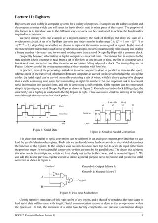
serial information into parallel form, and this is done using a shift register. Shift registers can be constructed
simply by joining up a set of D-type flip flops as shown in Figure 2. On each successive clock falling edge, the
data bit (Q) on a flip flop is loaded onto the flip flop on its right. Thus successive serial bits arriving at the input
travel through the register in four clock pulses.
Figure 1: Serial Data
Figure 2: Serial to Parallel Conversion
It is clear that parallel to serial conversion can be achieved in an analogous manner, provided that we can
load the parallel data into the register. To do this we need to add some further control circuitry which determines
the function of the register. In the simplest case we need to allow each flip flop to select its input either from
the previous stage (for serial/parallel conversion) or from an input bit for parallel load. The circuit that achieves
this selection is the multiplexer, which we have alredy met earlier in the course, and is shown in Figure 3. We
can add this to our previous register circuit to create a general purpose serial to parallel and parallel to serial
converter as shown in Figure 4.
Figure 3: Two Input Multiplexer
Clearly repetitive structures of this type can be of any length, and it should be noted that the time taken to
load serial data will increase with length. Serial communication cannot be done as fast as operations within
the processor. In fact, the inclusion of a serial load facility complicates our previous synchronous design
DOC112: Computer Hardware Lecture 11 1
2. Figure 4: A two function register
methodology, and therefore it is usual to use a separate clock from the system clock to convert between serial
and parallel systems, and to use other control lines to indicate when a conversion is complete and the register
can be read. The normal labelling convention for registers is that the most significant bit has the highest index
(PO3 above). They are usually drawn with the most significant bit on the left so that they conform to the same
conventions used to write a binary number. In Figure 4 the bits arrive least significant first, though this is not a
universal convention.
Serial to parallel conversion is not the only use of shift registers. It is well known that shifting a register
by one place to the left, and filling the bottom bit with zero, is equivalent to multiplying the number by two
(providing the register is long enough to represent the result), and conversely, shifting right is equivalent to
dividing by two. We could incorporate both serial to parallel conversion and multiplying and dividing by 2 in a
general purpose shift register. As an example we will design one with four modes defined as follows:
00 Hold
01 Shift Right
10 Shift Left
11 Parallel Load
The different modes can be selected using multiplexers. In this case we need a four way multiplexer. We can
build any multiplexer in two parts. The first it a binary to unary convertor, also known as a decoder. A 2-4
decoder is shown in Figure 5. The two input lines represent a two bit binary mumber, and the four output lines
are its unary representation. It will be clear that it is only possible for one of the four output lines to be 1 at any
one time. Using this as a component in its own right, we can design the four way multiplexer shown in Figure
6 simply by using the decoder outputs to control a gating circuit. This is really a four position switch, with the
position selected by the binary input on lines S0 and S!. The four input multiplexer can be incorporated into
Figure 5: Two bit Binary to Unary Converter
Figure 6: Four Input Multiplexer
the general purpose shift register of Figure 7. Here just one stage is shown, which is for bit i. A register of any
DOC112: Computer Hardware Lecture 11 2
3. length can be created by using one stage for each bit, connected as indicated in the figure. Each stage has one
multiplexer (MPX) connected to a D-Q flip flop. The parallel input is labelled PIi, and the papallel output POi.
Each multiplexer has the same control inputs (S1S0) so all multiplexers select the same input. Similarly all the
D-Q flip flops have the same clock, and change synchronously.
Figure 7: Four Function Register
Clocks and Registers
We have previously met registers in another form, namely counters, and we have seen that it is possible to
design them to operate in synchronisation with the system clock. It is sometimes useful to build counters for
the specific purpose of dividing clocks. We noted earlier in this lecture that loading a register serially may need
to be done at a rate that is slower than the processor clock. This is becaue serial transmission is limited by
the high capacitance in the long cables that need to be used. However, we would like the serial shift register
to work in synchronisation with the system clock, even if it is at a slower rate. it is possible to divide a clock
by two simply using the one bit counter shown in Figure 8. Here the value of D is taken directly from Q’,
and therefore at each clock pulse the flip flop will simply change state. If we look at the timing diagrams, we
see that Q will output a square wave which will be exactly half the frequency of the clock. We can therefore
consider the circuit a clock divider. For division by any other integer we can use a synchronous counter. If we
wish to divide a clock by say seven, we can do so by the circuit corresponding to the Moore machine of Figure
reffig:DivideBySeven. Remember that we just need to divide the number of falling edges in any time period by
seven. it doesn’t matter if the clock period is unevenly divided between 0 and 1.
Figure 8: Synchronous divide by two counter
Figure 9: Synchronous divide by seven
One obvious application of clock dividers is in wrist watches or quartz clocks. Here, the regulator is a
quartz crystal which has a characteristic property that allows a very accurate square wave of around 1MHz to
be produced. However, the stepper motor which drives the second hand needs one pulse every second, and
hence we need to interpose a circuit which divides the clock by 106. This can be done with a synchronous
counter with 20 stages, but, such a counter would have a lot of complex state sequencing logic. An alternative
DOC112: Computer Hardware Lecture 11 3
4. is to use a set of successive dividers. For example, we could design a circuit to divide by 256 by concatenating
two synchronous divide by sixteen circuits. In this configuration the clock input to the second stage is the output
of the first stage as shown in Figure 10. Designing a zero to sixteen counter is comparitively straight forward,
Figure 10: Asynchronous divide by 256 circuit
and hence, this strategy represents a viable way to achieve dividing by large numbers. However it is no longer
a synchronous counter since the second divide by 16 block changes after the first. Taking the above idea to
its simplest form, we could make our basic elements the divide by two circuit of Figure 8, and this creates a
famous circuit called the ripple through counter, which is shown in Figure 11. If a counter is to be limited to a
particular maximum value, then the ’clear’ input normally provided on a D-Q flip flop can be used. Thus, if we
wish to count to 5, then we would require three stages, and the ’clear’ input to each stage would be determined
by the minterm Q2 · Q1 · Q0, which in effect resets the counter to zero when it sees that the output is 5. This
principle can be extended easily to divide by any integer. It is very important to note that the ripple through
counter violates our principle of keeping the digital design synchronous. The correct state will only be present
on the outputs at a short time after the counting clock pulse, which will vary depending on how far the change
propagates. It is therefore very important to realise that this counter should be used only with extreme care, and
only when there is no time critical functionality in the circuit.
Figure 11: The ripple through counter
Figure 12: Count to five circuit
DOC112: Computer Hardware Lecture 11 4