

Recommended
More Related Content
What's hot
What's hot (20)
Viewers also liked
Viewers also liked (20)
Similar to Lathemachine 160329171046
Similar to Lathemachine 160329171046 (20)
Recently uploaded
Recently uploaded (20)
Lathemachine 160329171046
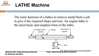
- 1. Module title: Engineering workshop Topic: Machining (Lathe machine) Dr.Abdullah Dhaiban LATHE Machine The main function of a lathes to remove metal from a job to give it the required shape and size. An engine lathe is the most basic and simplest form of the lathe. Fig: Working Principal of Lathe Machine
- 2. Module title: Engineering workshop Topic: Machining (Lathe machine) Dr.Abdullah Dhaiban LATHE Lathes are manufactured in a variety of types and sizes, from very small bench lathes used for precision work to huge lathes used for turning large steel shafts. But the principle of operation and function of all types of lathes is same
- 3. Module title: Engineering workshop Topic: Machining (Lathe machine) Dr.Abdullah Dhaiban Types of Lathe: 1. Speed lathe (a) Wood working (b) Spinning (c) Centering (d) Polishing 2. Centre or engine lathe (a) Belt drive (b) Individual motor drive (c) Gear head lathe 3. Bench lathe 4. Tool room Lathe 5. Capstan and Turret lathe 6. Special purpose lathe Whee1 lathe (b) Gap bed lathe (c) Dup1icating lathe (d) T-lathe 7. Automatic lathe
- 4. Module title: Engineering workshop Topic: Machining (Lathe machine) Dr.Abdullah Dhaiban Types of Lathe: Speed Lathe Speed lathe is simplest of all types of lathes in construction and operation. The important parts of speed lathe are following ((1) Bed (2) Headstock (3) Tailstock, (4) Tool post mounted on an adjustable slide.
- 5. Module title: Engineering workshop Topic: Machining (Lathe machine) Dr.Abdullah Dhaiban Types of Lathe: Centre Lathe or Engine Lathe: The term “engine” is associated with this lathe due to the fact that in the very early days of its development it was driven by steam engine. The engine lathe has all the basic parts, and contains additional mechanism for driving the lathe spindle at multiple speeds.
- 6. Module title: Engineering workshop Topic: Machining (Lathe machine) Dr.Abdullah Dhaiban Central Lathe Fig: Principal Components of a Central Lathe
- 7. Module title: Engineering workshop Topic: Machining (Lathe machine) Dr.Abdullah Dhaiban Types of Lathe: 6 Special Purpose Lathes These lathes are constructed for special purposes and for jobs, which cannot be accommodated or conveniently machined on a standard lathe. 3 Bench Lathe This is a small lathe usually mounted on a bench . 4- Tool Room Lathe This lathe has features similar to an engine lathe but it is much more accurately built 5 Capstan and Turret Lathe The distinguishing feature of this type of lathe is that the tailstock of an engine lathe is replaced by a hexagonal turret
- 8. Module title: Engineering workshop Topic: Machining (Lathe machine) Dr.Abdullah Dhaiban Types of Lathe: 6 Special Purpose Lathes These lathes are constructed for special purposes and for jobs, which cannot be accommodated or conveniently machined on a standard lathe. 7 Automatic Lathes These lathes are so designed that all the working and job handling movements of the complete manufacturing process for a job are done automatically
- 9. Module title: Engineering workshop Topic: Machining (Lathe machine) Dr.Abdullah Dhaiban Fig. Different Parts of Engine Lathe or Central Lathe
- 10. Module title: Engineering workshop Topic: Machining (Lathe machine) Dr.Abdullah Dhaiban 1 Bed The bed of a lathe machine is the base on which all other parts of lathe are mounted. 2- Head Stock The main function of headstock is to transmit power to the different parts of a lathe.
- 11. Module title: Engineering workshop Topic: Machining (Lathe machine) Dr.Abdullah Dhaiban 3- Tail Stock the tail stock of central lathe, which is commonly used for the objective of primarily giving an outer bearing and support the circular job being turned on centers Fig. Tail Stock of Central Lathe
- 12. Module title: Engineering workshop Topic: Machining (Lathe machine) Dr.Abdullah Dhaiban 4 Carriage Carriage is mounted on the outer guide ways of lathe bed and it can move in a direction parallel to the spindle axis. Fig. Tool Post of Center Lathe.
- 13. Module title: Engineering workshop Topic: Machining (Lathe machine) Dr.Abdullah Dhaiban 5 Feed Mechanism Feed mechanism is the combination of different units through which motion of headstock spindle is transmitted to the carriage of lathe machine . Following units play role in feed mechanism of a lathe machine- 1. End of bed gearing 2. Feed gear box 3. Lead screw and feed rod
- 14. Module title: Engineering workshop Topic: Machining (Lathe machine) Dr.Abdullah Dhaiban 6 Thread Cutting Mechanism The half nut or split nut is used for thread cutting in a lathe. It engages or disengages the carriage with the lead screw so that the rotation of the lead screw is used to traverse the tool along the work piece to cut screw threads
- 15. Module title: Engineering workshop Topic: Machining (Lathe machine) Dr.Abdullah Dhaiban ACCESSORIES AND ATTACHMENTS OF LATHE: Lathe centers: The most common method of holding the job in a lathe is between the two centers generally known as live center (head stock center) and dead center (tailstock center). Carriers or driving dog and catch plates: These are used to drive a job when it is held between two centers. Carriers or driving dogs are attached to the end of the job by a set screw. A use of lathe dog for holding and supporting the job is shown in
- 16. Module title: Engineering workshop Topic: Machining (Lathe machine) Dr.Abdullah Dhaiban ACCESSORIES AND ATTACHMENTS OF LATHE: Carriers or driving dog and catch plates: Fig. Lathe Dog
- 17. Module title: Engineering workshop Topic: Machining (Lathe machine) Dr.Abdullah Dhaiban ACCESSORIES AND ATTACHMENTS OF LATHE: Chucks Chuck is one of the most important devices for holding and rotating a job in a lathe. It’s basically attached to the headstock spindle of the lathe There are a number of types of lathe chucks, e.g. (1) Three jaws or universal (2) Four jaw independent chuck (3) Magnetic chuck (4) Collet chuck (5) Air or hydraulic chuck operated chuck (6) Combination chuck (7) Drill chuck.
- 18. Module title: Engineering workshop Topic: Machining (Lathe machine) Dr.Abdullah Dhaiban ACCESSORIES AND ATTACHMENTS OF LATHE: Face plates Face plates are employed for holding jobs, which cannot be conveniently held between centers or by chucks.
- 19. Module title: Engineering workshop Topic: Machining (Lathe machine) Dr.Abdullah Dhaiban ACCESSORIES AND ATTACHMENTS OF LATHE: Face plates Face plates are employed for holding jobs, which cannot be conveniently held between centers or by chucks. Angle plates Angle plate is a cast iron plate having two faces machined to make them absolutely at right angles to each other.
- 20. Module title: Engineering workshop Topic: Machining (Lathe machine) Dr.Abdullah Dhaiban ACCESSORIES AND ATTACHMENTS OF LATHE: Mandrels A mandrel is a device used for holding and rotating a hollow job that has been previously drilled or bored Rests A rest is a lathe device, which supports a long slender job, when it is turned between centers or by a chuck, at some intermediate point to prevent bending of the job due to its own weight and vibration set up due to the cutting force that acts on it.
- 21. Module title: Engineering workshop Topic: Machining (Lathe machine) Dr.Abdullah Dhaiban Operations, which can be performed in a lathe either by holding the work piece between centers or by a chuck are: 1. Straight turning 2. Shoulder turning 3. Taper turning 4. Chamfering 5. Eccentric turning 6. Thread cutting 7. Facing 8. Forming 9. Filing 10. Polishing 11. Grooving 12. Knurling 13. Spinning 14. Spring winding
- 22. Module title: Engineering workshop Topic: Machining (Lathe machine) Dr.Abdullah Dhaiban Operations which are performed by holding the work by a chuck or a faceplate or an angle plate are: 1. Undercutting 2. Parting-off 3. Internal thread cutting 4. Drilling 5. Reaming 6. Boring 7. Counter boring 8. Taper boring 9. Tapping Fig (B): Lathe Operation
- 23. Module title: Engineering workshop Topic: Machining (Lathe machine) Dr.Abdullah Dhaiban TAPERS AND TAPER TURNING A taper is defined as a uniform increase or decrease in diameter of a piece of work measured along its length. In a lathe machine, taper turning means to produce a conical surface by gradual reduction in diameter from a cylindrical job. Taper per inch = (D – d) /2l A taper can be turned by anyone of the Following methods: 1. By swiveling the compound rest, 2. By setting over the tailstock center, 3. by a broad nose form tool, 4. by a taper turning attachment 5 By combining longitudinal and cross feed in a special lathe and 6. By using numerical control lat
- 24. Module title: Engineering workshop Topic: Machining (Lathe machine) Dr.Abdullah Dhaiban
- 25. Module title: Engineering workshop Topic: Machining (Lathe machine) Dr.Abdullah Dhaiban Taper Turning with Tailstock set over Method
- 26. Module title: Engineering workshop Topic: Machining (Lathe machine) Dr.Abdullah Dhaiban THREAD CUTTING Fig: Thread Cutting