1. TRUSSES
A truss is a structure composed of members connected together in such a way as to resist
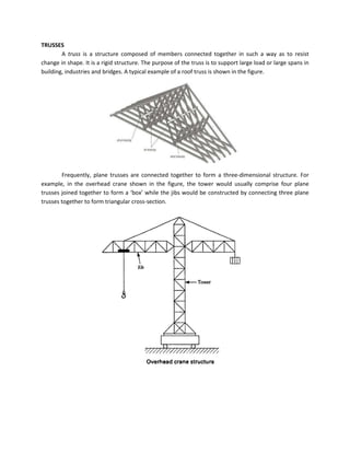
change in shape. It is a rigid structure. The purpose of the truss is to support large load or large spans in
building, industries and bridges. A typical example of a roof truss is shown in the figure.
Frequently, plane trusses are connected together to form a three-dimensional structure. For
example, in the overhead crane shown in the figure, the tower would usually comprise four plane
trusses joined together to form a ‘box’ while the jibs would be constructed by connecting three plane
trusses together to form triangular cross-section.
2. A Perfect or Rigid Truss
To make a truss rigid, its members must be connected together in such a way to prevent any
movement between them. The simplest pin-connected structure consists of three bars forming the
triangular truss shown.
Since all bars are rigid, their deformations (i.e., changes in their lengths) under external load P
are very small and negligible. Bar AB does not allow any change in the opposite angle C; similarly bar AC
prevents change in angle B and bar BC prevents any change in the angle A. Therefore, a triangular frame,
as shown, is known as a perfect truss or rigid truss. This is a stable truss.
A pin-connected structure composed of four bars is not a rigid truss but is a mechanism, in
which a specified motion of AB produces desired and predictable motion of members BC and CD. This is
basis of all machines. Here, all angles A, B, C and D change and therefore collapsible mechanism used for
transmission of power and motion from driving member AB to the coupler BC and the driven member
CD. This is known as a four-bar mechanism.
Adding a bar BD to the four-bar mechanism restores rigidity, while adding two bars AC and BD,
we get an over-rigid and statically indeterminate truss. Either member AD or BD is called redundant (not
necessary) member.
3. By removing one of the bars from this over-rigid truss we get the trusses shown in (a), (b) of the figure,
whereas in part (c) two bars are removed but stability is restored by adding a hinge at A in place of a
roller support.
Types of Trusses:
1. Simply supported (roller and hinge support)
2. Cantilever
3. Over hanging
5. Assumptions in the Analysis of Plane Truss
The following assumptions are made to simplify the analysis of truss
(1) Members of the truss are pin-connected to each other.
(2) Loads acts only at joints.
(3) Members of the truss are not subjected to bending moments.
(4) Members of the truss are rigid.
(5) Self weights of the members are negligible
(6) All members are of uniform cross-sections.
Idealization of a Truss
Loads are generally assumed to be applied at the intersection points of the members, so that
they are subjected principally to direct axial stresses. In practice trusses are not pin-joint but are
constructed, in the case of steel trusses, by bolting, riveting or welding the ends of the members to
gusset plates as shown in the figure.
6. Free-Body Diagram (FBD)
Difference between Trusses and Frames
ifference
Methods of Analysis
(1) Methods of joints
(2) Methods of sections