General system of forces unit 4 bce & engg mechanics
•Download as PPTX, PDF•
3 likes•1,036 views

engineering mechanics ( course content as per csvtu) reference A.K.TAYAL

Recommended
More Related Content
What's hot
What's hot (20)
Similar to General system of forces unit 4 bce & engg mechanics
Similar to General system of forces unit 4 bce & engg mechanics (20)
More from Parimal Jha
More from Parimal Jha (9)
Recently uploaded
Recently uploaded (20)
General system of forces unit 4 bce & engg mechanics
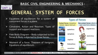
- 1. GENERAL SYSTEM OF FORCES Equations of equilibrium for a system of concurrent forces in a plane. Constraint, Action and Reaction. Types of support and support reactions. Free Body Diagram – Body subjected to two forces & Body subjected to three forces. Moment of a force. Theorem of Varignon, Equations of equilibrium. BASIC CIVIL ENGINEERING & MECHANICS : UNIT- 4 THIS SLIDE IS MADE BY PARIMAL JHA, H.O.D- CIVIL ENGG, C.E.C DURG, C.S.V.T.U ,CHATTISGARH
- 2. FORCE Force Action of one body on the other (push or pull) Point ofApplication Direction Magnitude
- 3. What is the need of knowing MECHANICS? Mechanics Deals with forces
- 4. TYPES OF APPLIED FORCES ▪ TENSION ▪ COMPRESSION ▪ BENDING / FLEXURE ▪ SHEAR ▪ TORSION ▪ COMBINED
- 5. CONCEPT OF ENGINEERING MECHANICS ▪ ENGINEERING MECHANICS is the science, which deals with the physical state of rest or motion of bodies under the action of forces . ▪ Depending upon the nature of the body involved it can be further divided into mechanics of Rigid body( deformable) or mechanics of solids and the mechanics of fluids MECHANICS FLUID MECHANICS SOLID MECHANICS
- 7. Mechanics Mechanics of Rigid Bodies Mechanics of Deformable Bodies Mechanics of Fluids Statics kinematics kinetics Dynamics
- 8. BRANCHES OF MECHANICS IN ENGINEERING
- 9. Statics Deals with forces and its effects when the body is at rest Dynamics Deals with forces and its effects when the body is in moving condition TrussBridge IC Engine
- 10. Studying forces on External effect of a body such as acceleration,velocity, displacement etc. Studying Internal effect of asforces on a body such stresses (internal resistance), change in shape etc. Rigid body mechanics Deformable body mechanics
- 11. Rigid body mechanics Negligible deformation (no deformation) under the action of forces. Assuming 100% strength in the materials. Large number of particles occupying fixed positions with each other. Actual structures and machines are never rigid under the action of external loads or forces. But the deformations induced are usually very small which does not affect the condition of equilibrium.
- 12. SOLID MECHANICS ▪ In this Subject we shall deal with the mechanics of rigid bodies, which do not deform under the action of applied forces ▪ A Rigid body is defined as a body on which the distance between two points never changes whatever be the force applied on it ▪ The mechanics of rigid bodies are studied in two parts statics (deals with bodies at rest) and dynamics (deals with bodies at motion) SOLID MECHANICS STATIC DYNAMIC
- 13. STUDY OF MECHANICS ▪ The study of mechanics involves concepts of space, time, mass and force. 1. Concept of SPACE is essential to fix the position of a point. To fully define position of a point in space we shall need to define some frame of reference and coordinate system. 2. Concept of TIME is essential to relate sequence of events, for example, starting and stopping of a motion of a body. 3. Concept of MASS is essential to distinguish between the behavior of two bodies under the action of identical force. 4. Concept of FORCE is essential as an agency which changes or tends to change the state of rest or of uniform motion of a body. A body can be said to be at rest or in motion only with respect to some reference frame. This reference should be fixed in space, so the earth surface is employed as reference frame.
- 14. FUNDAMENTAL PRINCIPLES ▪ The elementary mechanics rests on a few fundamental principles based on experimental observations, these are :- 1. Newton's three laws of motion 2. Newton's law of gravitation 3. The parallelogram law for the addition of forces 4. The principle of transmissibility of a force.
- 15. SYSTEMS OF UNITS ▪ FORCE = Mass x Acceleration ▪ F = m x a ▪ F= { mass x length/ (time)2 } ▪ Different system of units are : ▪ Centimetre gram sec system (C.G.S) ▪ Foot pound second system (F.P.S) ▪ Metre kilogram second system (M.K.S) ▪ International system of units (S.I) Force is a vector quantity thus rules of vector addition and subtraction are applicable to the addition and subtraction of forces
- 16. SYSTEMS OF UNITS
- 17. USEFUL FORMULAS IN MECHANICS
- 21. Types of forces Concurrent coplanar forces Non Concurrent coplanar (Parallel) Collinear forces Concurrent non-coplanar
- 22. ▪ A concurrent force system contains force whose line of action meets at one point CONCURRENT FORCES IN A PLANE force Scalar Vector ▪ SCALAR QUANTITY : Quantities like Time, Mass, Volume & Energy can be completely defined by stating their magnitudes.These quantities can be added and subtracted according to law of Algebra. ▪ VECTOR QUANTITY : Quantities like displacement ,Velocity ,Acceleration ,Momentum & force posses both magnitude as well as direction. To define these quantities we have to specify their magnitude, direction & point of action such quantities can be added according to the Parallelogram law are termed as vector quantities.
- 23. Components of a Force Plane Force Space Force
- 24. ADDITION OF TWO FORCES: PARALLELOGRAM LAW ▪ In Mechanics ,most of the time, we are concerned with the forces having an equivalent effect on the rigid body rather than equal forces ▪ The resultant of the two forces acting on a body ,in this sense, is equivalent force
- 25. Parallelogram law: Two forces acting on a particle can be replaced by the single component of a force (RESULTANT) by drawing diagonal of the parallelogram which has the sides equal to the givenforces. Parallelogram law cannot be proved mathematically . It is an experimental finding. A = point of application , AB= Magnitude , AC= Reference line B C B C 30o R = P + Q
- 26. Law of Triangle of forces ▪ Instead of constructing a parallelogram the sum of the resultant of two forces can be determined by the triangle law. ▪ Triangle law can be stated as : ▪ “If two forces acting at a point are represented by two sides of a triangle taken in order, then their sum or resultant is represented by the third side taken in an opposite order.” R = P+Q = Q+P
- 27. Law of Triangle of forces ▪ The remaining angles can be computed by using the law of sines as : α β γ R= √ P2+Q2 - 2PQ Cos β R= magnitude of the resultant R Angle β should be known for finding the magnitude P Q R sinγ sin α sinβ SUBTRACTION Here forces are working in opposite direction ADDITION
- 28. ▪ Q.1 – Two forces are acting at a point as shown in figure. Determine the magnitude and direction of the resultant. Trigonometric solution : Instead of drawing triangle to the scale and measuring resultant “R” we can determine it by applying law of cosines to the ▷ ABC R= √ P2+Q2 - 2PQ Cos β = √ 502 + 1002 – 2*50*100* cos 1500 = √21160 = 145.46 N
- 29. The two vectors can also be added by head to tail by using triangle law. Triangle law states that if three concurrent coplanar forces are acting at a point be represented in magnitude and direction by the sides of a triangle, then they are in static equilibrium.
- 30. Lami’s Theorem states that if three concurrent coplanar forces are acting at a point, then each force is directly proportional to the sine of the angle between the other two forces.
- 31. Lami’s theorem considering only the equilibrium of three forces acting on a point not the stress acting through a ropes or strings The principle of transmissibility is applicable only for rigid bodies not for deformable bodies
- 32. ▪ Point force ▪ Coplanar forces ▪ Non coplanar forces ▪ Concurrent forces ▪ Non concurrent forces ▪ Parallel forces ▪ General system of forces CONCEPT OF FORCES: Point force
- 33. CONCEPT OF SYSTEM OF FORCES:
- 34. ▪ The rectangular components Fx & Fy are also called the scalar components of force F F = √ FX 2 + FY 2 Tan θ = Fy Fx θ = angle between force F and X axis Concurrent force-Two or more forces are said to be concurrent at a point if their lines of action intersect at that point. The rectangular or Scalar Components of a Force in a plane
- 35. RESULTANT OF SEVERAL CONCURRENT COPLANAR FORCES BY SUMMING RECTANGULAR COMPONENTS (METHOD OF PROJECTIONS) Here forces P,Q & S are coplanar concurrent forces. Each forces acting at A can be replaced by its rectangular components in corresponding x & y direction as Rxi & Ryj ,these forces produce same effect on the particle as the forces themselves. Now algebraic sum of forces can be determined by adding in particular directions x & y as Σ Fx & Σ Fy .
- 36. F1 F2 F5 F4 F3 A B E D C Polygon Law of Forces “If many number of forces acting at a point can be represented as a sides of a polygon, then they are in equilibrium” F1 F2 F3F4 F5
- 37. Q.1 - Four forces act on bolt A as shown. Determine the resultant of the force on the bolt.
- 38. Q.1 - Four forces act on bolt A as shown. Determine the resultant of the force on the bolt. SOLUTION: • Resolve each force into rectangular components. • Determine the components of the resultant by adding the corresponding force components. • Calculate the magnitude and direction of the resultant.
- 39. Q.1 - Four forces act on bolt A as shown. Determine the resultant of the force on the bolt. Resolve each force into rectangular components.
- 40. Q.1 - Four forces act on bolt A as shown. Determine the resultant of the force on the bolt. Resolve each force into rectangular components. force Magnitude in N X component in N Y component in N F1 150 +129 +75 F2 80 -27.4 +75.2 F3 110 0 -110.0 F4 100 +96.6 -25.9
- 41. Q.1 - Four forces act on bolt A as shown. Determine the resultant of the force on the bolt. force Magnitude in N X component in N Y component in N F1 150 +129 +75 F2 80 -27.4 +75.2 F3 110 0 -110.0 F4 100 +96.6 -25.9 Fx= +199.1 Fy= +14.3 R = √ 199.12 +14.32 ,R = 199.6N Tanα = 14.3 N 199.1N , α = 4.1
- 42. Q.2 - Find the magnitude and direction of resultant R of 4 concurrent forces acting as shown in figure below ? 60o 90o 150o p 2p 4p 3 √3 p
- 43. Q.2 - Find the magnitude and direction of resultant R of 4 concurrent forces acting as shown in figure below ? ΣFx = -P/2 ΣFy = √3/2 x P 60o 90o 150o p 2p 4p 3 √3 p ΣFx = p cos 0+ 2p cos 60 + 3 √3 P cos 150 + 4p cos 300 ΣFy = p sin 0+ 2p sin 60 + 3 √3 P sin 150 + 4p sin 300
- 44. Q.2 - Find the magnitude and direction of resultant R of 4 concurrent forces acting as shown in figure below ? ΣFx = -P/2 ΣFy = √3/2 x P Resultant of forces R = √ RX 2 + RY 2 = √ (-P/2)2 + (√3/2 x P)2 = P 60o 90o 150o p 2p 4p 3 √3 p ΣFx = p cos 0+ 2p cos 60 + 3 √3 P cos 150 + 4p cos 300 ΣFy = p sin 0+ 2p sin 60 + 3 √3 P sin 150 + 4p sin 300 Tanα = (-1/2 P/√3/2 P) = -√3 α = tan-1 ( -√3 )
- 45. EQUATIONS OF EQUILIBRIUM FOR A SYSTEM OF CONCURRENT FORCES IN A PLANE ▪ Equations below are called the equilibrium equations, if a number of concurrent forces lying in a plane are in equilibrium, these equations are to be satisfied ΣFx = 0 ΣFy = 0 ▪ Equilibrium state means restriction of movement of body in any of the direction in the plane under application of forces.
- 48. TYPES OF SUPPORT AND SUPPORT REACTIONS
- 49. CONSTRAINT ACTION AND REACTION
- 52. ▪ A free body diagram consists primarily of a sketch of the body in question and arrows representing the forces applied to it (TO the body) Another way is to say the force of something ON the body. How to find out forces and reactions of a body subjected to applied forces : 1. Isolate Body ▪ There must be only 1 body. Make sure you isolate the body exactly – as if you cut it out in a silhouette or outline. It is important to be very clear about the boundary you have made around the body. 2. Find Force locations ▪ Forces are applied by contact, gravity or inertia. Identify all the points where forces are applied to the body. Gravity always acts through the centre of mass, pressure acts through the centre of pressure. ▪ The only forces to consider are those that CROSSTHE BOUNDARY. Ignore all other forces. FREE BODY DIAGRAM
- 53. 3. Line of Action of Forces ▪ Point contact: ‘Smooth’: No friction. Force can only be applied perpendicular to smooth surface. Wheels: Perpendicular to surface and acting through Centre of axle. ▪ Cable. Force can only be tensile (pulling). Force must be along direction of cable. ▪ Pin Joint: Force can be any direction but no moment around pin. ▪ Other Joints: Solid: Force in any direction, moment in any direction. Slider: Moment any direction. Force perpendicular to slider ▪ Gravitational. Centre of gravity ▪ Inertial. Centre of inertia (not always the same as C.O.G).These are due to acceleration. ▪ Fluid pressures. Usually taken as a single resultant force in statics calculations, acting through the Centre of pressure. ▪ Other. Magnetic, electrostatic (charge) etc. These are pretty rare outside of electric equipment design. 4. Direction of the Forces ▪ Include all the forces actingTOTHE BODY.The direction is determined by thinking TO the body, or ON the body. Eg Gravity acts down ON the body, floor pushes up ON the body, what does the road doTO the wheel…etc.
- 57. Couple Two equal and opposite forces are acting at some distance forming a couple
- 58. How Rotational Effect will change with distance?
- 59. Free body diagram Isolated body from the structure of machinery which shows all the forces and reaction forces acting on it.
- 60. Examples for free body diagram
- 61. Examples of Free Body Diagrams :