
Recommended
More Related Content
What's hot
What's hot (20)
Viewers also liked
Viewers also liked (15)
Similar to Technical Aspects of EHV XLPE Cable End Termination and on Site Brief Procedure
Similar to Technical Aspects of EHV XLPE Cable End Termination and on Site Brief Procedure (20)
Recently uploaded
Recently uploaded (20)
Technical Aspects of EHV XLPE Cable End Termination and on Site Brief Procedure
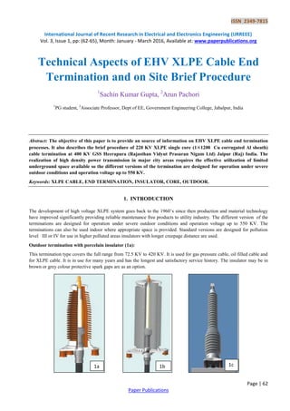
- 1. ISSN 2349-7815 International Journal of Recent Research in Electrical and Electronics Engineering (IJRREEE) Vol. 3, Issue 1, pp: (62-65), Month: January - March 2016, Available at: www.paperpublications.org Page | 62 Paper Publications Technical Aspects of EHV XLPE Cable End Termination and on Site Brief Procedure 1 Sachin Kumar Gupta, 2 Arun Pachori 1 PG student, 2 Associate Professor, Dept of EE, Government Engineering College, Jabalpur, India Abstract: The objective of this paper is to provide an source of information on EHV XLPE cable end termination processes. It also describes the brief procedure of 220 KV XLPE single core (1 1200 Cu corrugated Al sheath) cable termination at 400 KV GSS Heerapura (Rajasthan Vidyut Prasaran Nigam Ltd) Jaipur (Raj) India. The realization of high density power transmission in major city areas requires the effective utilization of limited underground space available so the different versions of the termination are designed for operation under severe outdoor conditions and operation voltage up to 550 KV. Keywords: XLPE CABLE, END TERMINATION, INSULATOR, CORE, OUTDOOR. 1. INTRODUCTION The development of high voltage XLPE system goes back to the 1960’s since then production and material technology have improved significantly providing reliable maintenance free products to utility industry. The different version of the terminations are designed for operation under severe outdoor conditions and operation voltage up to 550 KV. The terminations can also be used indoor where appropriate space is provided. Standard versions are designed for pollution level III or IV for use in higher polluted areas insulators with longer creepage distance are used. Outdoor termination with porcelain insulator (1a): This termination type covers the full range from 72.5 KV to 420 KV. It is used for gas pressure cable, oil filled cable and for XLPE cable. It is in use for many years and has the longest and satisfactory service history. The insulator may be in brown or grey colour protective spark gaps are as an option. 1a 1b 1c
- 2. ISSN 2349-7815 International Journal of Recent Research in Electrical and Electronics Engineering (IJRREEE) Vol. 3, Issue 1, pp: (62-65), Month: January - March 2016, Available at: www.paperpublications.org Page | 63 Paper Publications Outdoor termination with composite insulator (1b): This termination type is for XLPE cable. The basic design is identical with that of the porcelain termination. The composite insulator, however, is of much lower weight. This is advantageous with respect to lifting equipment needed for installation and also for supporting constructions. Dry type outdoor termination (1c): The dry type termination for XLPE cable is completely free from any liquid or gaseous filling medium. Apart from the environmental aspect, the dry design provides further advantages like easier installation and no need for filling equipment, both contributing to significant savings for installation of the terminations. 2. OUTDOOR TERMINATION PROCESS OF 220 KV XLPE CABLE 1 1200 CU CORRUGATED AL SHEATH 220 KV single circuit of 1200 sq mm 220 KV single core XLPE cable is established between 400 KV substation Heerapura to 220 KV GIS substation Nala Power House Jaipur (appox 10 km) against specification No RVPN/ EHV/ TN- 278. General instruction preparatory works, Dimensions used, fitting procedure are strictly as per site work. During the work relevant security and accident rules must be obeyed. The cable laying must be finished, the cable end is properly sealed and for the proposed cable position the admissible bending radii must be taken into consideration during work. Starting from the upper surface of the termination frame, mark the reference line on the outer plastic cable sheath. Mark from the reference line the cutting position (over length=insulator length +900 mm) on the cable. Adjust the cable end in straight jointing position and fix it. Remove the plastic cable sheath and corrugated aluminum sheath. Taking into consideration the working length of the used round peeling device and an additional length of 10 mm for the grinding process apply a mark with insulating tape on the insulation screen in direction to the cable so that the cable core can be peeled with the peeling device to the transition D1/cone. The knife must be adjusted step by step so that the insulation screen is completely removed. When grinding with emery the diameter of the cable core is reduced by approx 0.3 mm. The transition spot from D1 to D2 must be marked. The peeling process is to be carried out as described under size D1 ,whereby the knife must be adjusted step by step so that diameter D2 as correlated to the stress cone is reached. The transition from D1 to D2 elaborated conically by means of a rasp and abrasive cloth. Make a cone for pushing over the stress cone at the end of the cable core. The prepared cable core may not show any unclean areas like coarse, abrasion channels or marks of the rasp. Longitudinal variations at the end of the insulation screen must be checked. The max. Allowed length is W=15mm. Apply one layer of semi conducting tape from the corrugated aluminum sheath to the semi conducting layer of the cable. Wrap a centre lapping of self amalgamating tape on the corrugated aluminium sheath and on the cable core. Push the cable gland including sealing ring over the cable core. Push over the base plate with the pedestal insulators over the cable core fix them to the termination frame.
- 3. ISSN 2349-7815 International Journal of Recent Research in Electrical and Electronics Engineering (IJRREEE) Vol. 3, Issue 1, pp: (62-65), Month: January - March 2016, Available at: www.paperpublications.org Page | 64 Paper Publications Clean the cable core and the stress cone inner bore, cover the stress cone inner bore and the surface of the cable core with filling oil very well. Push the stress cone over the cable core up to the marked position by hand. Wash off the remainder of the lubricant from stress cone and cable core. Wrap one layer of semi conducting tape with 50% overlapping, copper woven fabric tape and self-amalgamating tape from the tube of the sealing flange to the stress cone. Cut the cable core exactly vertical at the cutting position (insulator length +3 mm). Push the mechanical connector on the conductor up to the insulation and fix all screw by hand. Clean the base plate, the stress cone, the core and the insulator carefully. Insert the sealing ring on the base plate. Push on the insulator and allow it to stand on the base plate. Screw the insulator to the base plate and the aluminum top plate. Take care that no dirt can get into the open termination. Fit a stud to the can and pour the oil into the insulator up to the oil level. The air chamber over the filling height, allow heat expansion of the oil. Push the spacers over the conductor terminal bolt. Insert the sealing ring in the groove of the conductor terminal. Screw the top nut on the bolt. Fit the cable gland and heat shrinkable sleeve.
- 4. ISSN 2349-7815 International Journal of Recent Research in Electrical and Electronics Engineering (IJRREEE) Vol. 3, Issue 1, pp: (62-65), Month: January - March 2016, Available at: www.paperpublications.org Page | 65 Paper Publications 3. CONCLUSION The outdoor terminal should be suitable for heavily polluted atmospheric conditions with total creep age distance of 31 mm/KV and protected creep age distance of not more than 50% of the total creep age distance. The cable end terminals for terminating the cable shall be fully compatible with the cable. Above termination is antifog, pre fabricated type based on the EPR-based stress relief cone with an epoxy housing or pre-moulded type silicon based stress relief cone. The termination base plate and the cable’s metallic sheath shall be electrically insulated from the supporting structure. REFERENCES [1] W. Weissenberg, U. Rengel, R. Scherer, “EHV XLPE Cable Systems up to 400 kV – More than 10 Years Field Experience,” CIGRE 2004, paper B1-102, 2004. [2] Ruben Vogelsang, Oldrich Sekula, Herbert Nyffenegger, & Werner Weissenberg, “Long-term experiences with XLPE cable systems up to 550 kV,” CIGRE SC B1, 2009. [3] R. V. Olshausen, & W. Weissenberg, “The electrical long-term performance of cross- linked polyethylene,” 30 WIRE 5/2001. [4] W. Weissenberg, M. Kuschel, “Test methods for Silicone Rubber accessories used in high voltage cables up to 400 kV,” 6th Jicable, Paris, 2003. [5] CIGRÉ Tech. Brochure # 379, “Update of service experience of HV underground & submarine cable systems,” 2009. [6] J.-O. Boström, A. Campus, R. N. Hamton, & E. Marsden, “Reliable HV & EHV XLPE cables,” CIGRE, Paper 21- 105, 2002. [7] HIGH VOLTAGE XLPE CABLE SYSTEMS Technical User Guide BRUGG CABLES E-Highway2050 WP3 workshop April 15th, 2014 Brussels. [8] Underground Cable: an innovative and reliable Technology nkt cables. [9] High voltage underground and subsea cable technology options for future transmission in Europe Ernesto Zaccone, Chairman Europe a cable High Voltage Systems Group. [10] LONG-LIFE XLPE INSULATED POWER CABLE jicable 07 Nigel HAMPTON, NEETRAC, Georgia Tech, USA, Rick HARTLEIN, NEETRAC, Georgia Tech, USA, Hakan LENNARTSSON, Borouge Pty, Hong Kong, Harry ORTON, OCEI, Vancouver, BC, Canada, h.Ram RAMACHANDRAN,The Dow Chemical Company, NJ, USA, [11] D.H.Kim and E.J.Park,“An investigation of influence of semiconductive electrode materials in breakdown and charge International Journal of Scientific Engineering and Technology (ISSN : 2277-1581) www.ijset.com, Volume No.1, Issue No.2 pg:65-70 01 April 2012 accumulation in XLPE,” in Proc. IEEE Conf. Elect. Insulation Dielect.Phenomena, Atlanta, GA, 1998, pp. 546–549. [12] M.S.Mashikan, J.H. Groeger, S.J. Dale and E. Ildstad, “Role of semi conductive compounds in the premature aging of XLPE cable insulation,” in Conf. record IEEE Int. Symp.n Elect. Insulation, Bos- ton,MA, June 5–8, 1988, pp. 314–320. [13] Feasibility and technical aspects of partial undergrounding of extra high voltage power transmission lines Brussels, December 2010 europa cables.