SlideShare a Scribd company logo
1 of 30
Download to read offline
UNIT V
Synchronization in Distributed Systems:
1.Clock Synchronization
2. Mutual Exclusion
3.E-tech Algorithm ( Not available anywhere)
4.Bully Algorithm
5.Ring Algorithm
6.Atomic Transactions
Deadlocks:
1.Deadlock in Distributed systems
2.Distributed deadlock prevention and distributed deadlock
detection
Bully Algorithm
Bully Algorithm was developed by a scientist Garcia Molina in 1982. When a
process notices that the coordinator is no longer responding to requests, it
initiates an election. A process, P, holds an election as follows:
1. P sends an ELECTION message to all processes with higher numbers
2. If no one responds, P wins the election and becomes coordinator
3. If one of the higher ups answers, it takes over. P’s job is done.
At any moment, a process can get an ELECTION message from one of its lower
numbered colleagues. When such a message arrives, the receiver sends an OK
message back to the sender to indicate that he is alive and will take over. The
receiver then holds an election, unless it is already holding one. Finally, all
processes give up but one will not and that one is the new coordinator. It
announces its victory by sending all processes a message telling them that
starting immediately it is the new coordinator.
If a process that was previously down comes back up, it holds an election. If it
happens to be the highest numbered process currently running, it will win the
election and take over the coordinator’s job. Thus the biggest guy in town
always wins, hence the name “ Bully Algorithm”
In the above figure we see an example of how the bully algorithm works. The
group consists of eight processes, numbered from 0 to 7. Previously process 7
was the coordinator, but it has just crashed. Process 4 is the first one to
notice this, so it sends ELECTION messages to all the processes higher than it,
namely 5, 6, 7 as shown in fig (a).
Processes 5 and 6 both respond with OK, as shown in fig ( b). Upon getting the
first of these responses, 4 knows that its job is over. It knows that one of these
bigwigs will take over and become coordinator. It just sits back and waits to
see who the winner will be.
Ring Algorithm
Another election algorithm is based on the use of a ring, but without a token.
In this scenario we assume that the processes are physically or logically
ordered, so that each process knows who its successor is. When any process
notices that the coordinator is not functioning, it builds an ELECTION message
containing its own process number and sends the message to its successor. If
the successor is down, the sender skips over the successor and goes to the
next member along the ring, or the one after that, until a running process is
located. At each step, the sender adds its own process number to the list in
the message.
Finally, the message gets back to the process that started it
all. That process recognizes this event when it receives an incoming message
containing its own process number. At that point, the message type is changed
to COORDINATOR and circulated once again, this time to inform everyone else
who the coordinator is( the list member with the highest number) and who the
members of the new ring are. When this message has circulated once, it is
removed and everyone goes back to work.
In the above figure we see what happens if two processes, 2 and 5, discover
simultaneously that the previous coordinator, process 7, has crashed. Each of
these builds an ELECTION message and starts circulating it. Finally, both these
messages will go all the way around, and both 2 and 5 will convert them into
COORDINATOR messages, with exactly the same members and in the same
order. When both have gone around again, both will be removed. It does no
harm to have extra messages circulating at most it wastes a little bandwidth.
Mutual Exclusion
Systems involving multiple processes are often most easily programmed using
critical regions, When a process has to read or update certain shared data
structures, It first enters a critical region to achieve mutual exclusion and
ensure that no other process will use the shared data structures at the same
time. In single processor systems, critical regions are protected using
semaphores, monitors and similar constructs.
We will see in the below that how critical regions and mutual exclusions can
be implemented in distributed systems.
Centralized Algorithm
The most straightforward way to achieve mutual exclusion in a distributed
system is to simulate how it is done in a one processor system. One process is
elected as the coordinator(e.g.. the one running on the machine with the
highest network address). Whenever a process wants to enter a critical
region, it sends a request message to the coordinator stating which critical
region it wants to enter and asking for permission. If no other process is
currently in that critical region, the coordinator sends back a reply granting
permissions as shown in fig (a)
Now suppose that another process 2 asks for permission to enter the
same critical region. The coordinator knows that a different process is already
in the critical region, so it cannot grant permission. The exact method used to
deny permission is system dependent. In fig (b), the coordinator just refrains
from replying, thus blocking process 2, which is waiting for a reply.
Alternatively, it could send a reply saying “ permission denied. “ Either way, it
queues the request from 2 for the time being.
When process 1 exits the critical region, it sends a message to the
coordinator releasing its exclusive access, as shown in fig (c). The coordinator
takes the first item off the queue of deferred requests and sends that process
a grant message. If the process was still blocked ( i.e this is the first message
to it), It unblocks and enters the critical region. If an explicit message has
already been sent denying permission, the process will have to poll for
incoming traffic, or block later. Either way, when it sees the grant, it can
enter the critical region.
It is easy to see that the algorithm guarantees mutual exclusion: the
coordinator only lets one process at a time into each critical region. It is also
fair, since requests are granted in the order in which they are received. No
process ever waits forever ( no starvation). The scheme is easy to implement
too, and requires only three messages per use of a critical region ( request,
grant, release). It can also be used for more general resource allocation rather
than just managing critical regions.
The centralized approach also has shortcomings. The coordinator is a
single point of failure, so if it crashes, the entire system may go down. If
processes normally block after making a request, they cannot distinguish a
dead coordinator from “ permission denied” since in both cases no message
comes back. In addition, in a large system, a single coordinator can become a
performance bottleneck.
Distributed Algorithm
Having a single point of failure is frequently unacceptable, so researchers have
looked for distributed mutual exclusion algorithms and the algorithm works as
follows. When a process wants to enter a critical region, it builds a message
containing the name of the critical region it wants to enter, its process
number, and the current time. It then sends the message to all other
processes, conceptually including itself. The sending of messages is assumed to
be reliable; i.e every message is acknowledged. Reliable group communication
if available, can be used instead of individual messages.
When a process receives a request message from another process,
the action it takes depends on its state with respect to the critical region
named in the message. Three cases have to be distinguished:
1. If the receiver is not in the critical region and doesn’t want to enter it, it
sends back an OK message to the sender.
2. If the receiver is already in the critical region, it doesn’t reply, instead ,
it queues the request.
3. If the receiver wants to enter the critical region but has not yet done so
it compares the timestamp in the incoming message with the one
contained in the message that it has sent everyone.The lowest one wins.
If the incoming message is lower, the receiver sends back an OK
message. If its own message has a lower stamp, the receiver queues the
incoming request and sends nothing.
After sending out request asking permission to enter a critical region, a
process sits back and waits until everyone else has given permission. As soon
as all the permissions are in, it may enter the critical region. When it exits the
critical region, it sends OK messages to all processes on its queue and deletes
them all from the queue.
Let us try to understand why the algorithm works. If there is no
conflict, it clearly works. However, suppose that two processes try to enter
the same critical region simultaneously, as shown in fig (a)
Process sends everyone a request with timestamp 8, while at the same time,
process 2 sends everyone a request with timestamp 12, Process 1 is not
interested in entering the critical region, so it sends OK to both senders.
Process 0 and 2 both see the conflict and compare timestamps. Process 2 sees
that it has lost, so it grants permission to 0 by sending OK. Process 0 now
queues the request from 2 for later processing and enters the critical region,
as shown in fig (b).
When it is finished, it removes the request from 2 from its queue and sends an
OK message to process 2, allowing the latter to enter its critical region, as
shown in fig ( c ).The algorithm works because in the case of a conflict, the
lowest timestamp wins and everyone agrees on the ordering of the
timestamps.
Note that the situation in fig a,b,c would have been essentially
different if process 2 had sent its message earlier in time so that process 0 had
gotten it and granted permission before making its own request. In this case, 2
would have noticed that it itself was in a critical region at the time of the
request, and queued it instead of sending a reply.
As with the centralized algorithm discussed above, mutual exclusion is
guaranteed without deadlock or starvation. The number of messages required
per entry is now 2(n-1), where the total number of processes in the system is
n. Best of all, no single point of failure exists.
Unfortunately, the single point of failure has been replaced by n
points of failure. If any process crashes, it will fail to respond to requests. This
silence will be interpreted ( incorrectly) as denial of permission, thus blocking
all subsequent attempts by all processes failing is n times as large as a single
coordinator failing; we have managed to replace a poor algorithm with one
that is n times worse and requires much more network traffic to boot.
The algorithm can be patched up by the same trick
that we proposed earlier, when a request comes in, the receiver always sends
a reply, either granting or denying permission. Whenever either a request or a
reply, either granting or denying permission. Whenever either a request or a
reply is lost, the sender times out and keeps trying until either a reply comes
back or the sender concludes that the destination is dead, After a request is
denied the sender should block waiting for a subsequent OK message.
Another problem with this algorithm is that either a group
communication primitive must be used, or each process must maintain the
group membership list itself, including processes entering the group, leaving
the group, and crashing. The method works best with small groups of
processes that never change their group memberships.
Finally, recall that one of the problems with the centralized algorithm
is that making it handle all requests can lead to a bottleneck. In the
distributed algorithm, all processes are involved in all decisions concerning
entry into critical regions. If one process is unable to handle the load, it is
unlikely that forcing everyone to do exactly the same thing in parallel is going
to help much.
Various minor improvements are possible to this algorithm. For example,
getting permission from everyone to enter a critical region is really overkill.
All that is needed is a method to prevent two processes from entering the
critical region at the same time. The algorithm can be modified to allow a
process to enter a critical region when it has collected permission from a
simple majority of the other processes, rather than from all of them. Of
course, in this variation after a process has granted permission to one process
to enter a critical region, it cannot grant the same permission to another
process until the first one has released that permission.
Token Ring Algorithm
A completely different approach to achieving mutual exclusion in a distributed
system is shown in fig 3.10. Here we have a bus network as shown in a ( e.g
Ethernet). with no inherent ordering of the process. In software a logical ring
is constructed in which each process is assigned a position in the ring as shown
in (b). The ring positions may be allocated in numerical order of network
addresses or some other means. It doesn’t matter what the ordering is. All
that matters is that each process knows who is next in line after itself.
When the ring is initialized, a process 0 is given a token. The
token circulates around the ring. It is passed from process k to process k+1 (
modulo the ring size) in point to point messages. When a process acquires the
token from its neighbor, it checks to see if it is attempting to enter a critical
region. If so the process enters the region, does all the work it needs to, and
leaves the region. After it has exited, it passes the token along the ring. It is
not permitted to enter a second critical region using the same token.
If a process is handed the token by its neighbor and is not
interested in entering a critical region, it just passes it along. As a
consequence, when no processes want to enter any critical regions, the token
just circulates at high speed around the ring.
The correctness of this algorithm is evident. Only one process has the
token at any instant, so only one process can be in a critical region. Since the
token circulates among the processes in a well defined order, starvation
cannot occur. Once a process decides it wants to enter a critical region, at
worst it will have to wait for every other process to enter and leave one
critical region.
As usual this algorithm has problems too, If the token is ever lost, it must
be regenerated. In fact , detecting that it is lost is difficult, since the amount
of time between successive appearances of the token on the network is
unbounded. The fact that the token has not been spotted for an hour doesn’t
mean that it has been lost; somebody may still be using it.
The algorithm also runs into trouble if a process crashes, but recovery
is easier than in the other cases. If we require a process receiving the token to
acknowledge receipt, a dead process will be detected when its neighbor tries
to give it the token and fails. At that point the dead process can be removed
from the group, and the token holder can throw the token over the head of
the dead process to the next member down the line, or the one after that, if
necessary. Of course, doing so requires that everyone maintains the current
ring configuration.
Comparison between all the three algorithms
Deadlocks in Distributed System
Deadlocks in Distributed systems are similar to deadlocks in single processor
systems, only worse. They are harder to avoid, prevent or even detect and
harder to cure when tracked down because all the relevant information is
scattered over many machines.
In some systems, such as distributed database systems, they can be extremely
serious, so it is important to understand how they differ from ordinary
deadlocks and what can be done about them.
Some people make a distinction between two kinds of distributed deadlocks:
communication deadlocks and resource deadlocks. A communication deadlock
occurs, for example, when process A is trying to send a message to process B,
which in turn is trying to send one to process C, which is trying to send one to
A. There are various scenarios in which this situation leads to deadlock, such
as no buffers being available. A resource deadlock occurs when processes are
fighting over exclusive access to I/O devices, files, locks or other resources.
We will now focus on Deadlock Detection and Deadlock prevention
Centralized Deadlock Detection
As a first attempt, we can use a centralized deadlock detection algorithm and
try to imitate the non distributed algorithm. Although each machine maintains
the resource graph for its own processes and resources, a central coordinator
maintains the resource graph for the entire system ( the union of all the
individual graphs). When the coordinator detects a cycle, it kills off one
process to break the deadlock.
Unlike the centralized case, where all the information is
automatically available in the right place, in a distributed system it has to be
sent there explicitly. Each machine maintains the graph for its own processes
and resources. Several possibilities exist for getting it there. First, whenever
an arc is added or deleted from the resource graph, a message can be sent to
the coordinator providing the update. Second, periodically every process can
send a list of arcs added or deleted since the previous update. This method
requires fewer messages than the first one. Third, the coordinator can ask for
information when it needs it.
Unfortunately, none of these methods work well. Consider a system with
processes A and B running on machine 0, and process C running on machine 1.
Three resources exist: R, S, and T. Initially, the situation is as shown in fig
3.23 (a) and (b): A holds S but wants R, which it cannot have because B is
using it . C has T and wants S, too. The coordinator’s view of the world is
shown in fig 3.23(c). This configuration is safe. As soon as B finishes, A can get
R and finish, releasing S for C.
After a while, B releases R and asks for T, a perfectly legal and safe
swap. Machine 0 sends a message to the coordinator announcing the release of
R, and machine 1 sends a message to the coordinator announcing the fact that
B is now waiting for its resource, T. Unfortunately, the message from machine
1 arrives first, leading the coordinator to construct the graph of fig (d). The
coordinator incorrectly concludes that a deadlock exist and kills some process.
Such a situation is called a false deadlock. Many deadlock algorithms in
distributed systems produce false deadlocks like this due to incomplete or
delayed information.
One possible way out might be to use Lamport’s algorithm to provide
global time. Since the message from machine 1 to the coordinator is triggered
by the request from machine 0, the message from machine 1 to the
coordinator will indeed have a later timestamp than the message from
machine 0 to the coordinator. When the coordinator gets the message from
machine 1 that leads it to suspect deadlock, it could send a message to every
machine in the system saying: “ I just received a message with timestamp T
which leads to deadlock. If anyone has a message for me with an earlier
timestamp, please send it immediately.” When every machine has replied,
positively or negatively, the coordinator will see that the arc from R to B has
vanished, so the system is still safe. Although this method eliminates the false
deadlock, it requires global time and is expensive. There are some other
situations which are exist where eliminating false deadlock is much harder.
Distributed Deadlock Detection
In this there is an algorithm which is developed by Chandy –Misra Haas
algorithm. In this algorithm, processes are allowed to request multiple
resources (e.g., locks) at once, instead of one at a time. By allowing multiple
requests simultaneously, the growing phase of a transaction can be speeded up
considerably, The consequence of this change to the model is that a process
may now wait on two or more resources simultaneously.
In fig 3-24, we present a modified resource graph, where only
the processes are shown. Each arc passes through a resource as usual. Notice
that process 3 on machine 1 is waiting for two resources, one held by process 4
and one held by process 5.
Some of the processes are waiting for local resources, such as process
1, but others, such are process 2, are waiting for resources that are located on
a different machine. It is precisely these cross machine arcs that make looking
for cycles difficult. The Chady Misra Haas algorithm is invoked when a process
has to wait for some resource, for example, process 0 blocking on process 1.
At that point a special probe message is generated and sent to the process ( or
processes) holding the needed resources. The message consists of three
numbers: the process that just blocked, the process sending the message, and
the process to whom it is being sent. The initial message from 0 to 1 contains
the triple (0,0,1).
When the message arrives, the recipient checks to see if it itself is waiting for
any processes. If so, the message is updated, keeping the first field but
replacing the second field by its own process number and the third one by the
number of the process it is waiting for. The message is then sent to the
process on which it is blocked. If it is blocked on multiple processes, all of
them are sent ( different messages). This algorithm is followed whether the
resource is local or remote. In fig 3-24 we see the remote message labeled
(0,2,3), (0,4,6), and (0,8,0). If a message goes all the way around and comes
back to the original sender, i.e the process listed in the first field, a cycle
exists and the system is deadlocked.
There are various ways in which the deadlock can be broken. One way
is to have the process that initiated the probe commit suicide. However, this
method has problems if several processes invoke the algorithm simultaneously.
In fig 3-24, for example, imagine that both 0 and 6 block at the same moment,
and both initiate probes. Each would eventually discover the deadlock, and
each would kill itself. This is overkill.
An alternative algorithm is to have each process
add its identity to the end of the probe message so that when it returned to
the initial sender, the complete cycle would be listed. The sender can then
see which process has the highest number, and kill that one or send it a
message asking it to kill itself. Either way, if multiple processes discover the
same cycle at the same time, they will all choose the same victim.
Distributed Deadlock Prevention
Deadlock prevention consists of carefully designing the system so that
deadlocks are structurally impossible. Various techniques include allowing
processes to hold only one resource at a time, requiring processes to request
all their resources initially, and making processes release all resources when
asking for a new one. All of these are cumbersome in practice. A method that
sometimes works is to order all the resources and require processes to acquire
them in strictly increasing order. This approach means that a process can
never hold a high resource and ask for a low one, thus making cycles
impossible.
However, in a distributed system with global time and atomic
transactions, two other practical algorithms are possible. Both are based on
the idea of assigning each transaction a global timestamp at the moment it
starts. As in many timestamp-based algorithms, in these two it is very
important that no two transactions are ever assigned exactly the same
timestamp. As we have seen Lamport’s algorithm guarantees uniqueness (
effectively by using process numbers to break ties).
The idea behind the algorithm is that when one process is about to
block waiting for a resource that another process is using, a check is made to
see which has a larger timestamp ( i.e is younger). We can then allow the wait
only if the waiting process has a lower timestamp ( is older) than the process
waited for. In this manner, following any chain of waiting processes, the
timestamps always increase, so cycles are impossible. Alternatively we can
allow processes to wait only if the waiting process has a higher timestamp ( is
younger) than the process waited for, in which case the timestamps decrease
along the chain.
Although both methods prevent deadlocks, it is wiser to give priority to
older processes. They have run longer, so the system has a larger investment
in them, and they are likely to hold more resources. Also, a young process that
is killed off will eventually age until it is oldest one in the system, so this
choice eliminates starvation. As we have pointed out before, killing a
transaction is relatively harmless, since by definition it can be restarted safely
later.
To make this algorithm cleared, consider the situation of fig 3.25 In (a) an old
process wants a resource held by a young process. In (b) a young process wants
a resource held by an old process. In one case we should allow the process to
wait, in the other we should kill it. Suppose that we label (a) dies and (b)
wait. Then we are killing off an old process trying to use a resource held by a
young process, which is inefficient. Thus we must label it the other way, as
shown in fig. Under these conditions, the arrows always point in the direction
of increasing transaction numbers, making cycles impossible. This algorithm is
called wait-die.
Once we are assuming the existence of transactions, we can do something that
had previously been forbidden: take resources away from running processes. In
effect we are saying that when a conflict arises, instead of killing the process
making the request, we can kill the resource owner. Without transactions,
killing a process might have severe consequences, since the process might
have modified files, for example. With transactions, these effects will vanish
magically when the transaction dies.
Now consider the situation of fig 3.26 where we are going to
allow preemption. Given that our system believes in ancestor worship, as we
discussed above, we do not want a young whippersnapper preempting a
venerable old sage, so fig (a) and not fig (b) is labeled preempt. We can now
safely label fig (b) as wait. This algorithm is known as wound wait, because
one transaction is supposedly wounded ( it is actually killed) and the other
waits.
If an old process wants a resource held by a young one, the old process
preempts the young one, whose transaction is then killed, as shown in fig
3.26(a). The young one probably starts up again immediately, and tries to
acquire the resource, leading to fig (b), forcing it to wait. Contrast to this
algorithm with wait-die. There, if an oldtimer wants a resource held by a
young squirt, the oldtimer waits politely. However, if the young one wants a
resource held by the old one, the young one is killed. It will undoubtedly start
up again and be killed again. This cycle may go on many times before the old
one releases the resource. Wound-wait doesn’t have this nasty property.
Atomic Transaction
System Model or Transaction Model:
A collection of instructions or operations that performs a single logical
function is called a transaction. A major issue in processing transactions is the
preservation of atomicity despite the possibility of failures within the
computer system.
We can think of a transaction as a program unit that accesses and
perhaps updates various data items that reside on a disk within some files.
From our point of view such a transaction is simply a sequence of read and
write operations terminated by either a commit operation or an abort
operation.
A commit operation signifies that the transaction has terminated its execution
successfully, whereas an abort operation signifies that the transaction has
ended its normal execution due to some logical error or a system failure. If a
terminated transaction has completed its execution successfully, it is
committed otherwise it is aborted.
Since an aborted transaction may already have modified the data that it has
accessed, the state of these data may not be the same as it would have been
if the transaction had executed atomically. So that atomicity is ensured,an
aborted transaction must have no effect on the state of the data that it has
already modified. Thus, the state of the data accessed by an aborted
transaction must be restored to what it was just before the transaction started
executing. We say that such a transaction has been rolled back. It is a part of
the responsibility of the system to ensure this property.
To determine how the system should ensure atomicity, we need first to
identify the properties of devices used for storing the various data accessed by
the transactions. Various types of storage media are distinguished by their
relative speed, capacity, and resilience to failure.
Volatile storage: Information residing in volatile storage doesn’t usually
survive system crashes. Examples of such storage are main and cache memory.
Access to volatile storage is extremely fast, both because of the speed of the
memory access itself and because it is possible to access directly any data
item in volatile storage.
Non volatile storage: Information residing in non volatile storage usually
survives system crashes. Examples of media for such storage are disks and
magnetic tapes. Disks are more reliable than main memory but less reliable
than magnetic tapes. Both disks and tapes, however are subject to failure
which may result in loss of information.
Stable storage: Information residing in stable storage is never lost.To
implement an approximation of such storage, we need to replicate information
in several non volatile storage caches (usually disk) with independent failure
modes and to update the information in a controlled manner
Implementation of Atomic Transaction
If each process executing a transaction just updates the objects it uses ( files,
database, records, etc) in place then the transactions will not be atomic and
changes will not vanish magically if the transaction aborts. There are 2
methods which are commonly used
Private Workspace
When a process starts a transaction, it is given a private workspace containing
all the files ( and other objects) to which it has access. Until the transaction
either commits or aborts, all of its reads and writes go to the private
workspace, rather than the real one by which we mean the normal file system.
This observation leads directly to the first implementation method: actually
giving a process a private workspace at the instant it begins a transaction.
The problem with this technique is that the cost of copying
everything to a private workspace is prohibitive, but various optimizations
make it feasible. The first optimization is based on the realization that when a
process reads a file but doesn’t modify it, there is no need for a private copy.
It can just use the real one ( unless it has been changed since the transaction
started). Consequently, when a process starts a transaction, it is sufficient to
create a private workspace for it that is empty except for a pointer back to its
parent’s workspace. When the transaction is at the top level, the parent’s
workspace is the real file system. When the process opens a file for reading,
the back pointers are followed until the file is located in the parent’s
workspace.
When a file is opened for writing, it can be located in the
same way as for reading, except that now it is first copied to the private
workspace. However, a second optimization removes most of the copying,
even here. Instead of copying the entire file, only the file’s index is copied
into the private workspace. The index is the block of data associated with
each file telling where its disk blocks are. In UNIX, the index is the I node.
Using the private index, the file can be read in the usual way, since the disk
addresses it contains are for the original disk blocks. However, when a file
block is first modified, a copy of the block is made and the address of the copy
inserted into the index, as shown in fig 3.18. The block can then be updated
without affecting the original. Appended blocks are handled this way too. The
new blocks are sometimes called shadow blocks.
From fig (b), the process running the transaction sees the modified file, but all
other processes continue to see the original file. In a more complex
transaction, the private workspace might contain a large number of files
instead of just one. If the transaction aborts, the private workspace is simply
deleted and all the private blocks that it points to are put back on the free
list. If the transaction commits, the private indices are moved into the
parent’s workspace automatically as shown in fig (c). The blocks which are no
longer reachable are put onto the free list.
Write head Log
The other common method of implementing transactions is the write head
log, sometimes called an intentions list. With this method, files are actually
modified in place, but before any block is changed, a record is written to the
write head log on stable storage telling which transaction is making the
change, which file and block is being changed, and what the old and new
values are. Only after the log has been written successfully is the change made
to the file.
Fig 3.19 gives an example of how the log works. In fig 3.19 (a) we have
a simple transaction that uses two shared variables ( or other objects),x,y,
both initialized to 0. For each of the three statements inside the transaction,
a log record is written before executing the statement, giving the old and new
values, separated by a slash.
If the transaction succeeds and is committed, a commit record is written to
the log, but the data structures do not have to be changed, as they have
already been updated. If the transaction aborts, the log can be used to back
up to the original state. Starting at the end and going backward, each log
record is read and the change described in it undone. This action is called a
rollback.
The log can also be used for recovering from crashes. Suppose that
the process doing the transaction crashes just after having written the last log
record of fig 3.19(d), but before changing x. After the failed machine is
rebooted, the log is checked to see if any transactions were in progress at the
time of the crash. When the last record is read and the current value of x is
seen to be 1, it is clear that the crash occurred before the update was made,
so x is set to 4. If, on the other hand, x is 4 at the time of recovery, it is
equally clear that the crash occurred after the update , so nothing need be
changed. Using the log, it is possible to go forward( do the transaction) or go
backward ( undo the transaction).
Two phase commit protocol
As we have pointed out repeatedly, the action of committing a transaction
must be done atomically, i.e instantaneously and indivisibly. In a distributed
system, the commit may require the cooperation of multiple processes on
different machines, each of which holds some of the variables, files, and
databases, and other objects changed by the transaction.
The protocol we will look at is called the two phase commit
protocol. Although it is not the only such protocol, it is probably the most
widely used. The basic idea is shown in fig 3.20. One of the processes involved
functions as the coordinator.Usually, this is the one executing the transaction.
The commit protocol begins when the coordinator writes a log entry saying
that it is starting the commit protocol, followed by sending each of the other
processes involved ( the subordinates) a message telling them to prepare to
commit.
When a subordinate gets the message it checks to see if it is ready to commit,
makes a log entry, and sends back its decision. When the coordinator has
received all the responses, it knows whether to commit or abort. If all the
processes are prepared to commit, the transaction is committed. If one or
more are unable to commit ( or do not respond), the transaction is aborted.
Either way, the coordinator writes a log entry and then sends a message to
each subordinate informing it of the decision. It is this write to the log that
actually commits the transaction and makes it go forward no matter what
happens afterward.
Due to the use of the log on stable storage, this protocol is highly
resilient in the face of multiple crashes. If the coordinator crashes after having
written the initial log record, upon recovery it can just continue where it left
off, repeating the initial message if need be. If it crashes after having written
the result of the vote to the log, upon recovery it can just reinform all the
subordinates of the result. If a subordinate crashes before having replied to
the first message, the coordinator will keep sending it messages, until it gives
up. If it crashes later, it can see from the log where it was and thus what it
must do.
Concurrency control
When multiple transactions are executing simultaneously in different
processes ( on different processors), some mechanism is needed to keep them
out of each other’s way. That mechanism is called a concurrency control
algorithm.
Locking
The oldest and most widely used concurrency control algorithm is locking. In
the simplest form, when a process needs to read or write a file ( or other
object) as a part of transaction, it first locks the file. Locking can be done
using a single centralized lock manager, or with a local lock manager on each
machine for managing local files. In both cases the lock manager maintains a
list of locked files, and rejects all attempts to lock files that are already
locked by another process. Since well behaved processes do not attempt to
access a file before it has been locked, setting a lock on a file keeps everyone
else away from it and thus ensures that it will not change during the lifetime
of the transaction.
Locks are normally acquired and released by the transaction system and do not
require action by the programmer.
This basic scheme is overly restrictive and can be improved by distinguishing
read locks from write locks. If a read lock is set on a file, other read locks are
permitted. Read locks are set to make sure that the file doesn’t change ( i.e
exclude all writers), but there is no reason to forbid other transactions from
reading the file. In contrast, when a file is locked for writing, no other locks of
any kind are permitted. Thus read locks are sharred, but write locks must be
exclusive.
For simplicity we have assumed that the unit of locking is the entire file.
In practice, it might be a smaller item, such as an individual record or page, or
a larger item, such as an entire database. The issue of how large an item to
lock is called granularity of locking. The finer the granularity, the more
precise the lock can be, and the more parallelism can be achieved ( e.g by not
blocking a process that wants to use the end of a file just because some other
process is using the beginning). On the other hand, fine grained locking
requires more locks, is more expensive, and is more likely to lead to
deadlocks.
Acquiring and releasing locks precisely at the moment they are needed or no
longer needed can lead to inconsistency and deadlocks. Instead, most
transactions that are implemented by locking use what is called two phase
locking.
Fig 3.21 shows the diagram for two phase locking. In which the process first
acquires all the locks it needs during the growing phase, then releases them
during the shrinking phase. If the process refrains from updating any files until
it reaches the shrinking phase, failure to acquire some lock can be dealt with
simply by releasing all locks, waiting a little while, and starting all
over.Furthermore, it can be proven that if all transactions use two phase
locking, all schedules formed by interleaving them are serializable. This is why
two phase locking is widely used.
In many systems the shrinking phase doesn’t take place until the
transaction has finished running and has either committed or aborted. This
policy, called strict two phase locking, has two main advantages. First, a
transaction always reads a value written by a committed transaction;
therefore one never has to abort a transaction because its calculations were
based on a file it should not have seen. Second, all lock acquisitions and
releases can be handled by the system without the transaction being awasre of
them: locks are acquired whenever a file is to be accessed and released when
the transaction has finished. This policy eliminates cascaded aborts: having to
undo a committed transaction because it saw a file it should not have seen.
Locking, even two phase locking, can lead to deadlocks. If two
processes each try to acquire the same pair of locks but in the opposite order,
a deadlock may result. The usual techniques apply here, such as acquiring all
locks in some canonical order to prevent hold and wait cycles. Also possible is
deadlock detection by maintaining an explicit graph of which process has
which locks and wants which locks, and checking the graph for cycles. Finally,
when it is known in advance that a lock will never be held longer than T sec, a
timeout scheme can be used: If a lock remains continuously under the same
ownership for longer than T sec, there must be a deadlock.
Optimistic concurrency control:
A second approach to handling multiple transactions at the same time is called
optimistic concurrency control.The idea beind this technique is very simple
and that is, Just go ahead and do whatever you want to , without paying
attention to what anybody else is doing. If there is a problem, worry about it
later. ( Many politicians use this algorithms too), In practice, conflicts are
relatively rare, so most of the time it works all right.
Although conflicts may be rare, they are not impossible,so some way is
needed to handle them. What optimistic concurrency control does is keep
track of which files have been read and written. At the the point of
committing, it checks all other transactions to see if any of its files have been
changed since the transaction started. If so, the transaction is aborted. If not,
it is committed.
Optimistic concurrency control fits best with the implementation based
on private workspaces. That way, each transaction changes its files privately,
without interference from the others. At the end, the new files are either
committed or released.
The big advantages of optimistic concurrency control are that it is deadlock
free and allows maximum parallelism because no process ever has to wait for a
lock. The disadvantage is that sometimes it may fail, in which case the
transacton has to be run all over again. Under conditions of heavy load, the
probability of failure may go up substantially, making optimistic concurrency
control a poor choice.
Time stamps
In this scenario , every file in the system has a read timestamp and a write
timestamp associated with it,telling which committed transaction last read
and wrote it, respectively. If transactions are short and widely spaced in time,
it will normally occur that when a process tries to access a file, the file’s read
and write timestamps will be lower ( older) than the current transaction’s
timestamp. This ordering means that the transactions are being processed in
the proper order, so everything is alright.
When the ordering is incorrect, it means that a transaction that
started later than the current one has manager to get in there, access the file,
and commit. This situation means that the current transaction is too late, so it
is aborted. In Kung and Robinson’s method, we are hoping that concurrent
transactions do not use the same files. In the timestamp method, we do not
mind if concurrent transactions use the same files, as long as the lower
numbered transaction always goes first.
It is easiest to explain the timestamp method by means of an example.
Imagine that there arre three transactions , alpha, beta and gamma. Alpha ran
a long time ago and used every file needed by beta and gamma, so all their
files have read and write timestamps set to alpha’s timestamp. Beta and
gamma start concurrently, with beta having a lower timestamp than gamma (
but higher than alpha, of course).
Let us first consider beta writing a file. Call its timestamp, T and the
read and write timestamps of the file to be written TRD and TWR respectively.
Unless gamma has snuck in already and committed, both TRD and TWR will be
alpha’s timestamp, and thus less than T. In fig 3.22 (a) and (b) we see that T is
laarger than both TRD and TWR( gamma has not already committed), so the
write is accepted and done tentatively. It will become permanent when beta
commits. Beta’s timestamp is now recorded in the file as a tentative write.
In fig (c ) and (d) beta is out of luck. Gamma has either read ( c) or written (d
) the file and committed. Beta’s transaction is aborted. However, it can apply
for a new timestamp and start all over again.
Now look at reads. In fig 3.22 ( c), there is no conflict, so the read
can happen immediately. In fig 3.22 (f), some interloper has gotten in there
and is trying to write the file. The interloper’s timestamp is lower than beta’s,
so beta simply waits until the interloper commits, at which time it can read
the new file and continue.
In fig 3.22 (g), gamma has changed the file and already committed. Again
beta must abort. In fig (h) gamma is in the process of changing the
file,although it has not committed yet. Still , beta is too late and must be
abort.
Timestamping has differrent properties than locking. When a transaction
encounters a larger ( later ) timestamp, it aborts, whereas under the saame
circumstances with locking it would either wait or be able to proceed
immediately. On the other hand, it is deadlock free, which is a big plus.

More Related Content

Similar to Advanced os 5th unit

Distributed Systems
Distributed SystemsDistributed Systems
Distributed Systemsguest0f5a7d
 
Communication And Synchronization In Distributed Systems
Communication And Synchronization In Distributed SystemsCommunication And Synchronization In Distributed Systems
Communication And Synchronization In Distributed Systemsguest61205606
 
Comparative Study of Mutual Exclusion Algorithms in Distributed Systems
Comparative Study of Mutual Exclusion Algorithms in Distributed SystemsComparative Study of Mutual Exclusion Algorithms in Distributed Systems
Comparative Study of Mutual Exclusion Algorithms in Distributed SystemsIJERA Editor
 
Ch17 OS
Ch17 OSCh17 OS
Ch17 OSC.U
 
DC Lecture 04 and 05 Mutual Excution and Election Algorithms.pdf
DC Lecture 04 and 05 Mutual Excution and Election Algorithms.pdfDC Lecture 04 and 05 Mutual Excution and Election Algorithms.pdf
DC Lecture 04 and 05 Mutual Excution and Election Algorithms.pdfLegesseSamuel
 
Chapter 5-Synchronozation.ppt
Chapter 5-Synchronozation.pptChapter 5-Synchronozation.ppt
Chapter 5-Synchronozation.pptsirajmohammed35
 
Chapter 18 - Distributed Coordination
Chapter 18 - Distributed CoordinationChapter 18 - Distributed Coordination
Chapter 18 - Distributed CoordinationWayne Jones Jnr
 
Leader Election Approach: A Comparison and Survey
Leader Election Approach: A Comparison and SurveyLeader Election Approach: A Comparison and Survey
Leader Election Approach: A Comparison and SurveyEditor Jacotech
 
Leader election approach a comparison and survey
Leader election approach a comparison and surveyLeader election approach a comparison and survey
Leader election approach a comparison and surveyEditor Jacotech
 
Chapter 7-Fault Tolerance.ppt
Chapter 7-Fault Tolerance.pptChapter 7-Fault Tolerance.ppt
Chapter 7-Fault Tolerance.pptHabib246314
 
8. mutual exclusion in Distributed Operating Systems
8. mutual exclusion in Distributed Operating Systems8. mutual exclusion in Distributed Operating Systems
8. mutual exclusion in Distributed Operating SystemsDr Sandeep Kumar Poonia
 
CHECKPOINTING WITH MINIMAL RECOVERY IN ADHOCNET BASED TMR
CHECKPOINTING WITH MINIMAL RECOVERY IN ADHOCNET BASED TMRCHECKPOINTING WITH MINIMAL RECOVERY IN ADHOCNET BASED TMR
CHECKPOINTING WITH MINIMAL RECOVERY IN ADHOCNET BASED TMRijujournal
 
CHECKPOINTING WITH MINIMAL RECOVERY IN ADHOCNET BASED TMR
CHECKPOINTING WITH MINIMAL RECOVERY IN ADHOCNET BASED TMRCHECKPOINTING WITH MINIMAL RECOVERY IN ADHOCNET BASED TMR
CHECKPOINTING WITH MINIMAL RECOVERY IN ADHOCNET BASED TMRijujournal
 
CHECKPOINTING WITH MINIMAL RECOVERY IN ADHOCNET BASED TMR
CHECKPOINTING WITH MINIMAL RECOVERY IN ADHOCNET BASED TMRCHECKPOINTING WITH MINIMAL RECOVERY IN ADHOCNET BASED TMR
CHECKPOINTING WITH MINIMAL RECOVERY IN ADHOCNET BASED TMRijujournal
 
Deadlock detection
Deadlock detectionDeadlock detection
Deadlock detectionNadia Nahar
 

Similar to Advanced os 5th unit (20)

Distributed Systems
Distributed SystemsDistributed Systems
Distributed Systems
 
Communication And Synchronization In Distributed Systems
Communication And Synchronization In Distributed SystemsCommunication And Synchronization In Distributed Systems
Communication And Synchronization In Distributed Systems
 
Comparative Study of Mutual Exclusion Algorithms in Distributed Systems
Comparative Study of Mutual Exclusion Algorithms in Distributed SystemsComparative Study of Mutual Exclusion Algorithms in Distributed Systems
Comparative Study of Mutual Exclusion Algorithms in Distributed Systems
 
Ch17 OS
Ch17 OSCh17 OS
Ch17 OS
 
OS_Ch17
OS_Ch17OS_Ch17
OS_Ch17
 
OSCh17
OSCh17OSCh17
OSCh17
 
DC Lecture 04 and 05 Mutual Excution and Election Algorithms.pdf
DC Lecture 04 and 05 Mutual Excution and Election Algorithms.pdfDC Lecture 04 and 05 Mutual Excution and Election Algorithms.pdf
DC Lecture 04 and 05 Mutual Excution and Election Algorithms.pdf
 
Chapter 5-Synchronozation.ppt
Chapter 5-Synchronozation.pptChapter 5-Synchronozation.ppt
Chapter 5-Synchronozation.ppt
 
Chapter 18 - Distributed Coordination
Chapter 18 - Distributed CoordinationChapter 18 - Distributed Coordination
Chapter 18 - Distributed Coordination
 
Leader Election Approach: A Comparison and Survey
Leader Election Approach: A Comparison and SurveyLeader Election Approach: A Comparison and Survey
Leader Election Approach: A Comparison and Survey
 
Leader election approach a comparison and survey
Leader election approach a comparison and surveyLeader election approach a comparison and survey
Leader election approach a comparison and survey
 
Distributed deadlock
Distributed deadlockDistributed deadlock
Distributed deadlock
 
Chapter 7-Fault Tolerance.ppt
Chapter 7-Fault Tolerance.pptChapter 7-Fault Tolerance.ppt
Chapter 7-Fault Tolerance.ppt
 
8. mutual exclusion in Distributed Operating Systems
8. mutual exclusion in Distributed Operating Systems8. mutual exclusion in Distributed Operating Systems
8. mutual exclusion in Distributed Operating Systems
 
CHECKPOINTING WITH MINIMAL RECOVERY IN ADHOCNET BASED TMR
CHECKPOINTING WITH MINIMAL RECOVERY IN ADHOCNET BASED TMRCHECKPOINTING WITH MINIMAL RECOVERY IN ADHOCNET BASED TMR
CHECKPOINTING WITH MINIMAL RECOVERY IN ADHOCNET BASED TMR
 
CHECKPOINTING WITH MINIMAL RECOVERY IN ADHOCNET BASED TMR
CHECKPOINTING WITH MINIMAL RECOVERY IN ADHOCNET BASED TMRCHECKPOINTING WITH MINIMAL RECOVERY IN ADHOCNET BASED TMR
CHECKPOINTING WITH MINIMAL RECOVERY IN ADHOCNET BASED TMR
 
CHECKPOINTING WITH MINIMAL RECOVERY IN ADHOCNET BASED TMR
CHECKPOINTING WITH MINIMAL RECOVERY IN ADHOCNET BASED TMRCHECKPOINTING WITH MINIMAL RECOVERY IN ADHOCNET BASED TMR
CHECKPOINTING WITH MINIMAL RECOVERY IN ADHOCNET BASED TMR
 
Transaction management transparencies
Transaction management transparenciesTransaction management transparencies
Transaction management transparencies
 
Deadlock detection
Deadlock detectionDeadlock detection
Deadlock detection
 
12EASApril-3412
12EASApril-341212EASApril-3412
12EASApril-3412
 

Recently uploaded

School management system project Report.pdf
School management system project Report.pdfSchool management system project Report.pdf
School management system project Report.pdfKamal Acharya
 
Ghuma $ Russian Call Girls Ahmedabad ₹7.5k Pick Up & Drop With Cash Payment 8...
Ghuma $ Russian Call Girls Ahmedabad ₹7.5k Pick Up & Drop With Cash Payment 8...Ghuma $ Russian Call Girls Ahmedabad ₹7.5k Pick Up & Drop With Cash Payment 8...
Ghuma $ Russian Call Girls Ahmedabad ₹7.5k Pick Up & Drop With Cash Payment 8...gragchanchal546
 
Digital Communication Essentials: DPCM, DM, and ADM .pptx
Digital Communication Essentials: DPCM, DM, and ADM .pptxDigital Communication Essentials: DPCM, DM, and ADM .pptx
Digital Communication Essentials: DPCM, DM, and ADM .pptxpritamlangde
 
1_Introduction + EAM Vocabulary + how to navigate in EAM.pdf
1_Introduction + EAM Vocabulary + how to navigate in EAM.pdf1_Introduction + EAM Vocabulary + how to navigate in EAM.pdf
1_Introduction + EAM Vocabulary + how to navigate in EAM.pdfAldoGarca30
 
Hospital management system project report.pdf
Hospital management system project report.pdfHospital management system project report.pdf
Hospital management system project report.pdfKamal Acharya
 
Theory of Time 2024 (Universal Theory for Everything)
Theory of Time 2024 (Universal Theory for Everything)Theory of Time 2024 (Universal Theory for Everything)
Theory of Time 2024 (Universal Theory for Everything)Ramkumar k
 
Online electricity billing project report..pdf
Online electricity billing project report..pdfOnline electricity billing project report..pdf
Online electricity billing project report..pdfKamal Acharya
 
HOA1&2 - Module 3 - PREHISTORCI ARCHITECTURE OF KERALA.pptx
HOA1&2 - Module 3 - PREHISTORCI ARCHITECTURE OF KERALA.pptxHOA1&2 - Module 3 - PREHISTORCI ARCHITECTURE OF KERALA.pptx
HOA1&2 - Module 3 - PREHISTORCI ARCHITECTURE OF KERALA.pptxSCMS School of Architecture
 
Unit 4_Part 1 CSE2001 Exception Handling and Function Template and Class Temp...
Unit 4_Part 1 CSE2001 Exception Handling and Function Template and Class Temp...Unit 4_Part 1 CSE2001 Exception Handling and Function Template and Class Temp...
Unit 4_Part 1 CSE2001 Exception Handling and Function Template and Class Temp...drmkjayanthikannan
 
AIRCANVAS[1].pdf mini project for btech students
AIRCANVAS[1].pdf mini project for btech studentsAIRCANVAS[1].pdf mini project for btech students
AIRCANVAS[1].pdf mini project for btech studentsvanyagupta248
 
UNIT 4 PTRP final Convergence in probability.pptx
UNIT 4 PTRP final Convergence in probability.pptxUNIT 4 PTRP final Convergence in probability.pptx
UNIT 4 PTRP final Convergence in probability.pptxkalpana413121
 
Jaipur ❤CALL GIRL 0000000000❤CALL GIRLS IN Jaipur ESCORT SERVICE❤CALL GIRL IN...
Jaipur ❤CALL GIRL 0000000000❤CALL GIRLS IN Jaipur ESCORT SERVICE❤CALL GIRL IN...Jaipur ❤CALL GIRL 0000000000❤CALL GIRLS IN Jaipur ESCORT SERVICE❤CALL GIRL IN...
Jaipur ❤CALL GIRL 0000000000❤CALL GIRLS IN Jaipur ESCORT SERVICE❤CALL GIRL IN...jabtakhaidam7
 
Navigating Complexity: The Role of Trusted Partners and VIAS3D in Dassault Sy...
Navigating Complexity: The Role of Trusted Partners and VIAS3D in Dassault Sy...Navigating Complexity: The Role of Trusted Partners and VIAS3D in Dassault Sy...
Navigating Complexity: The Role of Trusted Partners and VIAS3D in Dassault Sy...Arindam Chakraborty, Ph.D., P.E. (CA, TX)
 
Ground Improvement Technique: Earth Reinforcement
Ground Improvement Technique: Earth ReinforcementGround Improvement Technique: Earth Reinforcement
Ground Improvement Technique: Earth ReinforcementDr. Deepak Mudgal
 
Introduction to Data Visualization,Matplotlib.pdf
Introduction to Data Visualization,Matplotlib.pdfIntroduction to Data Visualization,Matplotlib.pdf
Introduction to Data Visualization,Matplotlib.pdfsumitt6_25730773
 
PE 459 LECTURE 2- natural gas basic concepts and properties
PE 459 LECTURE 2- natural gas basic concepts and propertiesPE 459 LECTURE 2- natural gas basic concepts and properties
PE 459 LECTURE 2- natural gas basic concepts and propertiessarkmank1
 
Design For Accessibility: Getting it right from the start
Design For Accessibility: Getting it right from the startDesign For Accessibility: Getting it right from the start
Design For Accessibility: Getting it right from the startQuintin Balsdon
 
Introduction to Serverless with AWS Lambda
Introduction to Serverless with AWS LambdaIntroduction to Serverless with AWS Lambda
Introduction to Serverless with AWS LambdaOmar Fathy
 

Recently uploaded (20)

School management system project Report.pdf
School management system project Report.pdfSchool management system project Report.pdf
School management system project Report.pdf
 
Ghuma $ Russian Call Girls Ahmedabad ₹7.5k Pick Up & Drop With Cash Payment 8...
Ghuma $ Russian Call Girls Ahmedabad ₹7.5k Pick Up & Drop With Cash Payment 8...Ghuma $ Russian Call Girls Ahmedabad ₹7.5k Pick Up & Drop With Cash Payment 8...
Ghuma $ Russian Call Girls Ahmedabad ₹7.5k Pick Up & Drop With Cash Payment 8...
 
Digital Communication Essentials: DPCM, DM, and ADM .pptx
Digital Communication Essentials: DPCM, DM, and ADM .pptxDigital Communication Essentials: DPCM, DM, and ADM .pptx
Digital Communication Essentials: DPCM, DM, and ADM .pptx
 
1_Introduction + EAM Vocabulary + how to navigate in EAM.pdf
1_Introduction + EAM Vocabulary + how to navigate in EAM.pdf1_Introduction + EAM Vocabulary + how to navigate in EAM.pdf
1_Introduction + EAM Vocabulary + how to navigate in EAM.pdf
 
Hospital management system project report.pdf
Hospital management system project report.pdfHospital management system project report.pdf
Hospital management system project report.pdf
 
Theory of Time 2024 (Universal Theory for Everything)
Theory of Time 2024 (Universal Theory for Everything)Theory of Time 2024 (Universal Theory for Everything)
Theory of Time 2024 (Universal Theory for Everything)
 
Online electricity billing project report..pdf
Online electricity billing project report..pdfOnline electricity billing project report..pdf
Online electricity billing project report..pdf
 
HOA1&2 - Module 3 - PREHISTORCI ARCHITECTURE OF KERALA.pptx
HOA1&2 - Module 3 - PREHISTORCI ARCHITECTURE OF KERALA.pptxHOA1&2 - Module 3 - PREHISTORCI ARCHITECTURE OF KERALA.pptx
HOA1&2 - Module 3 - PREHISTORCI ARCHITECTURE OF KERALA.pptx
 
Unit 4_Part 1 CSE2001 Exception Handling and Function Template and Class Temp...
Unit 4_Part 1 CSE2001 Exception Handling and Function Template and Class Temp...Unit 4_Part 1 CSE2001 Exception Handling and Function Template and Class Temp...
Unit 4_Part 1 CSE2001 Exception Handling and Function Template and Class Temp...
 
AIRCANVAS[1].pdf mini project for btech students
AIRCANVAS[1].pdf mini project for btech studentsAIRCANVAS[1].pdf mini project for btech students
AIRCANVAS[1].pdf mini project for btech students
 
Signal Processing and Linear System Analysis
Signal Processing and Linear System AnalysisSignal Processing and Linear System Analysis
Signal Processing and Linear System Analysis
 
UNIT 4 PTRP final Convergence in probability.pptx
UNIT 4 PTRP final Convergence in probability.pptxUNIT 4 PTRP final Convergence in probability.pptx
UNIT 4 PTRP final Convergence in probability.pptx
 
Jaipur ❤CALL GIRL 0000000000❤CALL GIRLS IN Jaipur ESCORT SERVICE❤CALL GIRL IN...
Jaipur ❤CALL GIRL 0000000000❤CALL GIRLS IN Jaipur ESCORT SERVICE❤CALL GIRL IN...Jaipur ❤CALL GIRL 0000000000❤CALL GIRLS IN Jaipur ESCORT SERVICE❤CALL GIRL IN...
Jaipur ❤CALL GIRL 0000000000❤CALL GIRLS IN Jaipur ESCORT SERVICE❤CALL GIRL IN...
 
Integrated Test Rig For HTFE-25 - Neometrix
Integrated Test Rig For HTFE-25 - NeometrixIntegrated Test Rig For HTFE-25 - Neometrix
Integrated Test Rig For HTFE-25 - Neometrix
 
Navigating Complexity: The Role of Trusted Partners and VIAS3D in Dassault Sy...
Navigating Complexity: The Role of Trusted Partners and VIAS3D in Dassault Sy...Navigating Complexity: The Role of Trusted Partners and VIAS3D in Dassault Sy...
Navigating Complexity: The Role of Trusted Partners and VIAS3D in Dassault Sy...
 
Ground Improvement Technique: Earth Reinforcement
Ground Improvement Technique: Earth ReinforcementGround Improvement Technique: Earth Reinforcement
Ground Improvement Technique: Earth Reinforcement
 
Introduction to Data Visualization,Matplotlib.pdf
Introduction to Data Visualization,Matplotlib.pdfIntroduction to Data Visualization,Matplotlib.pdf
Introduction to Data Visualization,Matplotlib.pdf
 
PE 459 LECTURE 2- natural gas basic concepts and properties
PE 459 LECTURE 2- natural gas basic concepts and propertiesPE 459 LECTURE 2- natural gas basic concepts and properties
PE 459 LECTURE 2- natural gas basic concepts and properties
 
Design For Accessibility: Getting it right from the start
Design For Accessibility: Getting it right from the startDesign For Accessibility: Getting it right from the start
Design For Accessibility: Getting it right from the start
 
Introduction to Serverless with AWS Lambda
Introduction to Serverless with AWS LambdaIntroduction to Serverless with AWS Lambda
Introduction to Serverless with AWS Lambda
 

Advanced os 5th unit

  • 1. UNIT V Synchronization in Distributed Systems: 1.Clock Synchronization 2. Mutual Exclusion 3.E-tech Algorithm ( Not available anywhere) 4.Bully Algorithm 5.Ring Algorithm 6.Atomic Transactions Deadlocks: 1.Deadlock in Distributed systems 2.Distributed deadlock prevention and distributed deadlock detection
  • 2. Bully Algorithm Bully Algorithm was developed by a scientist Garcia Molina in 1982. When a process notices that the coordinator is no longer responding to requests, it initiates an election. A process, P, holds an election as follows: 1. P sends an ELECTION message to all processes with higher numbers 2. If no one responds, P wins the election and becomes coordinator 3. If one of the higher ups answers, it takes over. P’s job is done. At any moment, a process can get an ELECTION message from one of its lower numbered colleagues. When such a message arrives, the receiver sends an OK message back to the sender to indicate that he is alive and will take over. The receiver then holds an election, unless it is already holding one. Finally, all processes give up but one will not and that one is the new coordinator. It announces its victory by sending all processes a message telling them that starting immediately it is the new coordinator. If a process that was previously down comes back up, it holds an election. If it happens to be the highest numbered process currently running, it will win the election and take over the coordinator’s job. Thus the biggest guy in town always wins, hence the name “ Bully Algorithm”
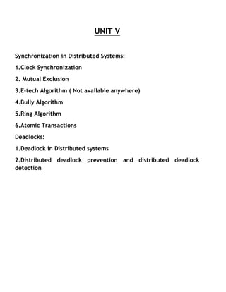
  • 3. In the above figure we see an example of how the bully algorithm works. The group consists of eight processes, numbered from 0 to 7. Previously process 7 was the coordinator, but it has just crashed. Process 4 is the first one to notice this, so it sends ELECTION messages to all the processes higher than it, namely 5, 6, 7 as shown in fig (a). Processes 5 and 6 both respond with OK, as shown in fig ( b). Upon getting the first of these responses, 4 knows that its job is over. It knows that one of these bigwigs will take over and become coordinator. It just sits back and waits to see who the winner will be.
  • 4. Ring Algorithm Another election algorithm is based on the use of a ring, but without a token. In this scenario we assume that the processes are physically or logically ordered, so that each process knows who its successor is. When any process notices that the coordinator is not functioning, it builds an ELECTION message containing its own process number and sends the message to its successor. If the successor is down, the sender skips over the successor and goes to the next member along the ring, or the one after that, until a running process is located. At each step, the sender adds its own process number to the list in the message. Finally, the message gets back to the process that started it all. That process recognizes this event when it receives an incoming message containing its own process number. At that point, the message type is changed to COORDINATOR and circulated once again, this time to inform everyone else who the coordinator is( the list member with the highest number) and who the members of the new ring are. When this message has circulated once, it is removed and everyone goes back to work.
  • 5. In the above figure we see what happens if two processes, 2 and 5, discover simultaneously that the previous coordinator, process 7, has crashed. Each of these builds an ELECTION message and starts circulating it. Finally, both these messages will go all the way around, and both 2 and 5 will convert them into COORDINATOR messages, with exactly the same members and in the same order. When both have gone around again, both will be removed. It does no harm to have extra messages circulating at most it wastes a little bandwidth. Mutual Exclusion Systems involving multiple processes are often most easily programmed using critical regions, When a process has to read or update certain shared data structures, It first enters a critical region to achieve mutual exclusion and ensure that no other process will use the shared data structures at the same time. In single processor systems, critical regions are protected using semaphores, monitors and similar constructs. We will see in the below that how critical regions and mutual exclusions can be implemented in distributed systems. Centralized Algorithm The most straightforward way to achieve mutual exclusion in a distributed system is to simulate how it is done in a one processor system. One process is elected as the coordinator(e.g.. the one running on the machine with the highest network address). Whenever a process wants to enter a critical region, it sends a request message to the coordinator stating which critical region it wants to enter and asking for permission. If no other process is currently in that critical region, the coordinator sends back a reply granting permissions as shown in fig (a) Now suppose that another process 2 asks for permission to enter the same critical region. The coordinator knows that a different process is already in the critical region, so it cannot grant permission. The exact method used to
  • 6. deny permission is system dependent. In fig (b), the coordinator just refrains from replying, thus blocking process 2, which is waiting for a reply. Alternatively, it could send a reply saying “ permission denied. “ Either way, it queues the request from 2 for the time being. When process 1 exits the critical region, it sends a message to the coordinator releasing its exclusive access, as shown in fig (c). The coordinator takes the first item off the queue of deferred requests and sends that process a grant message. If the process was still blocked ( i.e this is the first message to it), It unblocks and enters the critical region. If an explicit message has already been sent denying permission, the process will have to poll for incoming traffic, or block later. Either way, when it sees the grant, it can enter the critical region. It is easy to see that the algorithm guarantees mutual exclusion: the coordinator only lets one process at a time into each critical region. It is also fair, since requests are granted in the order in which they are received. No process ever waits forever ( no starvation). The scheme is easy to implement too, and requires only three messages per use of a critical region ( request, grant, release). It can also be used for more general resource allocation rather than just managing critical regions. The centralized approach also has shortcomings. The coordinator is a single point of failure, so if it crashes, the entire system may go down. If processes normally block after making a request, they cannot distinguish a dead coordinator from “ permission denied” since in both cases no message comes back. In addition, in a large system, a single coordinator can become a performance bottleneck.
  • 7. Distributed Algorithm Having a single point of failure is frequently unacceptable, so researchers have looked for distributed mutual exclusion algorithms and the algorithm works as follows. When a process wants to enter a critical region, it builds a message containing the name of the critical region it wants to enter, its process number, and the current time. It then sends the message to all other processes, conceptually including itself. The sending of messages is assumed to be reliable; i.e every message is acknowledged. Reliable group communication if available, can be used instead of individual messages. When a process receives a request message from another process, the action it takes depends on its state with respect to the critical region named in the message. Three cases have to be distinguished: 1. If the receiver is not in the critical region and doesn’t want to enter it, it sends back an OK message to the sender. 2. If the receiver is already in the critical region, it doesn’t reply, instead , it queues the request. 3. If the receiver wants to enter the critical region but has not yet done so it compares the timestamp in the incoming message with the one contained in the message that it has sent everyone.The lowest one wins. If the incoming message is lower, the receiver sends back an OK message. If its own message has a lower stamp, the receiver queues the incoming request and sends nothing. After sending out request asking permission to enter a critical region, a process sits back and waits until everyone else has given permission. As soon as all the permissions are in, it may enter the critical region. When it exits the critical region, it sends OK messages to all processes on its queue and deletes them all from the queue. Let us try to understand why the algorithm works. If there is no conflict, it clearly works. However, suppose that two processes try to enter the same critical region simultaneously, as shown in fig (a)
  • 8. Process sends everyone a request with timestamp 8, while at the same time, process 2 sends everyone a request with timestamp 12, Process 1 is not interested in entering the critical region, so it sends OK to both senders. Process 0 and 2 both see the conflict and compare timestamps. Process 2 sees that it has lost, so it grants permission to 0 by sending OK. Process 0 now queues the request from 2 for later processing and enters the critical region, as shown in fig (b). When it is finished, it removes the request from 2 from its queue and sends an OK message to process 2, allowing the latter to enter its critical region, as shown in fig ( c ).The algorithm works because in the case of a conflict, the lowest timestamp wins and everyone agrees on the ordering of the timestamps. Note that the situation in fig a,b,c would have been essentially different if process 2 had sent its message earlier in time so that process 0 had gotten it and granted permission before making its own request. In this case, 2 would have noticed that it itself was in a critical region at the time of the request, and queued it instead of sending a reply. As with the centralized algorithm discussed above, mutual exclusion is guaranteed without deadlock or starvation. The number of messages required per entry is now 2(n-1), where the total number of processes in the system is n. Best of all, no single point of failure exists.
  • 9. Unfortunately, the single point of failure has been replaced by n points of failure. If any process crashes, it will fail to respond to requests. This silence will be interpreted ( incorrectly) as denial of permission, thus blocking all subsequent attempts by all processes failing is n times as large as a single coordinator failing; we have managed to replace a poor algorithm with one that is n times worse and requires much more network traffic to boot. The algorithm can be patched up by the same trick that we proposed earlier, when a request comes in, the receiver always sends a reply, either granting or denying permission. Whenever either a request or a reply, either granting or denying permission. Whenever either a request or a reply is lost, the sender times out and keeps trying until either a reply comes back or the sender concludes that the destination is dead, After a request is denied the sender should block waiting for a subsequent OK message. Another problem with this algorithm is that either a group communication primitive must be used, or each process must maintain the group membership list itself, including processes entering the group, leaving the group, and crashing. The method works best with small groups of processes that never change their group memberships. Finally, recall that one of the problems with the centralized algorithm is that making it handle all requests can lead to a bottleneck. In the distributed algorithm, all processes are involved in all decisions concerning entry into critical regions. If one process is unable to handle the load, it is unlikely that forcing everyone to do exactly the same thing in parallel is going to help much. Various minor improvements are possible to this algorithm. For example, getting permission from everyone to enter a critical region is really overkill. All that is needed is a method to prevent two processes from entering the critical region at the same time. The algorithm can be modified to allow a process to enter a critical region when it has collected permission from a simple majority of the other processes, rather than from all of them. Of course, in this variation after a process has granted permission to one process
  • 10. to enter a critical region, it cannot grant the same permission to another process until the first one has released that permission. Token Ring Algorithm A completely different approach to achieving mutual exclusion in a distributed system is shown in fig 3.10. Here we have a bus network as shown in a ( e.g Ethernet). with no inherent ordering of the process. In software a logical ring is constructed in which each process is assigned a position in the ring as shown in (b). The ring positions may be allocated in numerical order of network addresses or some other means. It doesn’t matter what the ordering is. All that matters is that each process knows who is next in line after itself. When the ring is initialized, a process 0 is given a token. The token circulates around the ring. It is passed from process k to process k+1 ( modulo the ring size) in point to point messages. When a process acquires the token from its neighbor, it checks to see if it is attempting to enter a critical region. If so the process enters the region, does all the work it needs to, and leaves the region. After it has exited, it passes the token along the ring. It is not permitted to enter a second critical region using the same token. If a process is handed the token by its neighbor and is not interested in entering a critical region, it just passes it along. As a consequence, when no processes want to enter any critical regions, the token just circulates at high speed around the ring. The correctness of this algorithm is evident. Only one process has the token at any instant, so only one process can be in a critical region. Since the token circulates among the processes in a well defined order, starvation cannot occur. Once a process decides it wants to enter a critical region, at worst it will have to wait for every other process to enter and leave one critical region. As usual this algorithm has problems too, If the token is ever lost, it must be regenerated. In fact , detecting that it is lost is difficult, since the amount of time between successive appearances of the token on the network is
  • 11. unbounded. The fact that the token has not been spotted for an hour doesn’t mean that it has been lost; somebody may still be using it. The algorithm also runs into trouble if a process crashes, but recovery is easier than in the other cases. If we require a process receiving the token to acknowledge receipt, a dead process will be detected when its neighbor tries to give it the token and fails. At that point the dead process can be removed from the group, and the token holder can throw the token over the head of the dead process to the next member down the line, or the one after that, if necessary. Of course, doing so requires that everyone maintains the current ring configuration. Comparison between all the three algorithms
  • 12. Deadlocks in Distributed System Deadlocks in Distributed systems are similar to deadlocks in single processor systems, only worse. They are harder to avoid, prevent or even detect and harder to cure when tracked down because all the relevant information is scattered over many machines. In some systems, such as distributed database systems, they can be extremely serious, so it is important to understand how they differ from ordinary deadlocks and what can be done about them. Some people make a distinction between two kinds of distributed deadlocks: communication deadlocks and resource deadlocks. A communication deadlock occurs, for example, when process A is trying to send a message to process B, which in turn is trying to send one to process C, which is trying to send one to A. There are various scenarios in which this situation leads to deadlock, such as no buffers being available. A resource deadlock occurs when processes are fighting over exclusive access to I/O devices, files, locks or other resources. We will now focus on Deadlock Detection and Deadlock prevention Centralized Deadlock Detection As a first attempt, we can use a centralized deadlock detection algorithm and try to imitate the non distributed algorithm. Although each machine maintains the resource graph for its own processes and resources, a central coordinator maintains the resource graph for the entire system ( the union of all the individual graphs). When the coordinator detects a cycle, it kills off one process to break the deadlock. Unlike the centralized case, where all the information is automatically available in the right place, in a distributed system it has to be sent there explicitly. Each machine maintains the graph for its own processes and resources. Several possibilities exist for getting it there. First, whenever an arc is added or deleted from the resource graph, a message can be sent to the coordinator providing the update. Second, periodically every process can
  • 13. send a list of arcs added or deleted since the previous update. This method requires fewer messages than the first one. Third, the coordinator can ask for information when it needs it. Unfortunately, none of these methods work well. Consider a system with processes A and B running on machine 0, and process C running on machine 1. Three resources exist: R, S, and T. Initially, the situation is as shown in fig 3.23 (a) and (b): A holds S but wants R, which it cannot have because B is using it . C has T and wants S, too. The coordinator’s view of the world is shown in fig 3.23(c). This configuration is safe. As soon as B finishes, A can get R and finish, releasing S for C. After a while, B releases R and asks for T, a perfectly legal and safe swap. Machine 0 sends a message to the coordinator announcing the release of R, and machine 1 sends a message to the coordinator announcing the fact that B is now waiting for its resource, T. Unfortunately, the message from machine 1 arrives first, leading the coordinator to construct the graph of fig (d). The coordinator incorrectly concludes that a deadlock exist and kills some process. Such a situation is called a false deadlock. Many deadlock algorithms in distributed systems produce false deadlocks like this due to incomplete or delayed information.
  • 14. One possible way out might be to use Lamport’s algorithm to provide global time. Since the message from machine 1 to the coordinator is triggered by the request from machine 0, the message from machine 1 to the coordinator will indeed have a later timestamp than the message from machine 0 to the coordinator. When the coordinator gets the message from machine 1 that leads it to suspect deadlock, it could send a message to every machine in the system saying: “ I just received a message with timestamp T which leads to deadlock. If anyone has a message for me with an earlier timestamp, please send it immediately.” When every machine has replied, positively or negatively, the coordinator will see that the arc from R to B has vanished, so the system is still safe. Although this method eliminates the false deadlock, it requires global time and is expensive. There are some other situations which are exist where eliminating false deadlock is much harder. Distributed Deadlock Detection In this there is an algorithm which is developed by Chandy –Misra Haas algorithm. In this algorithm, processes are allowed to request multiple resources (e.g., locks) at once, instead of one at a time. By allowing multiple requests simultaneously, the growing phase of a transaction can be speeded up considerably, The consequence of this change to the model is that a process may now wait on two or more resources simultaneously. In fig 3-24, we present a modified resource graph, where only the processes are shown. Each arc passes through a resource as usual. Notice that process 3 on machine 1 is waiting for two resources, one held by process 4 and one held by process 5. Some of the processes are waiting for local resources, such as process 1, but others, such are process 2, are waiting for resources that are located on a different machine. It is precisely these cross machine arcs that make looking for cycles difficult. The Chady Misra Haas algorithm is invoked when a process has to wait for some resource, for example, process 0 blocking on process 1. At that point a special probe message is generated and sent to the process ( or processes) holding the needed resources. The message consists of three
  • 15. numbers: the process that just blocked, the process sending the message, and the process to whom it is being sent. The initial message from 0 to 1 contains the triple (0,0,1). When the message arrives, the recipient checks to see if it itself is waiting for any processes. If so, the message is updated, keeping the first field but replacing the second field by its own process number and the third one by the number of the process it is waiting for. The message is then sent to the process on which it is blocked. If it is blocked on multiple processes, all of them are sent ( different messages). This algorithm is followed whether the resource is local or remote. In fig 3-24 we see the remote message labeled (0,2,3), (0,4,6), and (0,8,0). If a message goes all the way around and comes back to the original sender, i.e the process listed in the first field, a cycle exists and the system is deadlocked. There are various ways in which the deadlock can be broken. One way is to have the process that initiated the probe commit suicide. However, this method has problems if several processes invoke the algorithm simultaneously. In fig 3-24, for example, imagine that both 0 and 6 block at the same moment, and both initiate probes. Each would eventually discover the deadlock, and each would kill itself. This is overkill. An alternative algorithm is to have each process add its identity to the end of the probe message so that when it returned to the initial sender, the complete cycle would be listed. The sender can then see which process has the highest number, and kill that one or send it a
  • 16. message asking it to kill itself. Either way, if multiple processes discover the same cycle at the same time, they will all choose the same victim. Distributed Deadlock Prevention Deadlock prevention consists of carefully designing the system so that deadlocks are structurally impossible. Various techniques include allowing processes to hold only one resource at a time, requiring processes to request all their resources initially, and making processes release all resources when asking for a new one. All of these are cumbersome in practice. A method that sometimes works is to order all the resources and require processes to acquire them in strictly increasing order. This approach means that a process can never hold a high resource and ask for a low one, thus making cycles impossible. However, in a distributed system with global time and atomic transactions, two other practical algorithms are possible. Both are based on the idea of assigning each transaction a global timestamp at the moment it starts. As in many timestamp-based algorithms, in these two it is very important that no two transactions are ever assigned exactly the same timestamp. As we have seen Lamport’s algorithm guarantees uniqueness ( effectively by using process numbers to break ties). The idea behind the algorithm is that when one process is about to block waiting for a resource that another process is using, a check is made to see which has a larger timestamp ( i.e is younger). We can then allow the wait only if the waiting process has a lower timestamp ( is older) than the process waited for. In this manner, following any chain of waiting processes, the timestamps always increase, so cycles are impossible. Alternatively we can allow processes to wait only if the waiting process has a higher timestamp ( is younger) than the process waited for, in which case the timestamps decrease along the chain. Although both methods prevent deadlocks, it is wiser to give priority to older processes. They have run longer, so the system has a larger investment
  • 17. in them, and they are likely to hold more resources. Also, a young process that is killed off will eventually age until it is oldest one in the system, so this choice eliminates starvation. As we have pointed out before, killing a transaction is relatively harmless, since by definition it can be restarted safely later. To make this algorithm cleared, consider the situation of fig 3.25 In (a) an old process wants a resource held by a young process. In (b) a young process wants a resource held by an old process. In one case we should allow the process to wait, in the other we should kill it. Suppose that we label (a) dies and (b) wait. Then we are killing off an old process trying to use a resource held by a young process, which is inefficient. Thus we must label it the other way, as shown in fig. Under these conditions, the arrows always point in the direction of increasing transaction numbers, making cycles impossible. This algorithm is called wait-die. Once we are assuming the existence of transactions, we can do something that had previously been forbidden: take resources away from running processes. In effect we are saying that when a conflict arises, instead of killing the process making the request, we can kill the resource owner. Without transactions, killing a process might have severe consequences, since the process might have modified files, for example. With transactions, these effects will vanish magically when the transaction dies.
  • 18. Now consider the situation of fig 3.26 where we are going to allow preemption. Given that our system believes in ancestor worship, as we discussed above, we do not want a young whippersnapper preempting a venerable old sage, so fig (a) and not fig (b) is labeled preempt. We can now safely label fig (b) as wait. This algorithm is known as wound wait, because one transaction is supposedly wounded ( it is actually killed) and the other waits. If an old process wants a resource held by a young one, the old process preempts the young one, whose transaction is then killed, as shown in fig 3.26(a). The young one probably starts up again immediately, and tries to acquire the resource, leading to fig (b), forcing it to wait. Contrast to this algorithm with wait-die. There, if an oldtimer wants a resource held by a young squirt, the oldtimer waits politely. However, if the young one wants a resource held by the old one, the young one is killed. It will undoubtedly start up again and be killed again. This cycle may go on many times before the old one releases the resource. Wound-wait doesn’t have this nasty property.
  • 19. Atomic Transaction System Model or Transaction Model: A collection of instructions or operations that performs a single logical function is called a transaction. A major issue in processing transactions is the preservation of atomicity despite the possibility of failures within the computer system. We can think of a transaction as a program unit that accesses and perhaps updates various data items that reside on a disk within some files. From our point of view such a transaction is simply a sequence of read and write operations terminated by either a commit operation or an abort operation. A commit operation signifies that the transaction has terminated its execution successfully, whereas an abort operation signifies that the transaction has ended its normal execution due to some logical error or a system failure. If a terminated transaction has completed its execution successfully, it is committed otherwise it is aborted. Since an aborted transaction may already have modified the data that it has accessed, the state of these data may not be the same as it would have been if the transaction had executed atomically. So that atomicity is ensured,an aborted transaction must have no effect on the state of the data that it has already modified. Thus, the state of the data accessed by an aborted transaction must be restored to what it was just before the transaction started executing. We say that such a transaction has been rolled back. It is a part of the responsibility of the system to ensure this property. To determine how the system should ensure atomicity, we need first to identify the properties of devices used for storing the various data accessed by the transactions. Various types of storage media are distinguished by their relative speed, capacity, and resilience to failure. Volatile storage: Information residing in volatile storage doesn’t usually survive system crashes. Examples of such storage are main and cache memory. Access to volatile storage is extremely fast, both because of the speed of the
  • 20. memory access itself and because it is possible to access directly any data item in volatile storage. Non volatile storage: Information residing in non volatile storage usually survives system crashes. Examples of media for such storage are disks and magnetic tapes. Disks are more reliable than main memory but less reliable than magnetic tapes. Both disks and tapes, however are subject to failure which may result in loss of information. Stable storage: Information residing in stable storage is never lost.To implement an approximation of such storage, we need to replicate information in several non volatile storage caches (usually disk) with independent failure modes and to update the information in a controlled manner Implementation of Atomic Transaction If each process executing a transaction just updates the objects it uses ( files, database, records, etc) in place then the transactions will not be atomic and changes will not vanish magically if the transaction aborts. There are 2 methods which are commonly used Private Workspace When a process starts a transaction, it is given a private workspace containing all the files ( and other objects) to which it has access. Until the transaction either commits or aborts, all of its reads and writes go to the private workspace, rather than the real one by which we mean the normal file system. This observation leads directly to the first implementation method: actually giving a process a private workspace at the instant it begins a transaction. The problem with this technique is that the cost of copying everything to a private workspace is prohibitive, but various optimizations make it feasible. The first optimization is based on the realization that when a process reads a file but doesn’t modify it, there is no need for a private copy. It can just use the real one ( unless it has been changed since the transaction started). Consequently, when a process starts a transaction, it is sufficient to create a private workspace for it that is empty except for a pointer back to its
  • 21. parent’s workspace. When the transaction is at the top level, the parent’s workspace is the real file system. When the process opens a file for reading, the back pointers are followed until the file is located in the parent’s workspace. When a file is opened for writing, it can be located in the same way as for reading, except that now it is first copied to the private workspace. However, a second optimization removes most of the copying, even here. Instead of copying the entire file, only the file’s index is copied into the private workspace. The index is the block of data associated with each file telling where its disk blocks are. In UNIX, the index is the I node. Using the private index, the file can be read in the usual way, since the disk addresses it contains are for the original disk blocks. However, when a file block is first modified, a copy of the block is made and the address of the copy inserted into the index, as shown in fig 3.18. The block can then be updated without affecting the original. Appended blocks are handled this way too. The new blocks are sometimes called shadow blocks.
  • 22. From fig (b), the process running the transaction sees the modified file, but all other processes continue to see the original file. In a more complex transaction, the private workspace might contain a large number of files instead of just one. If the transaction aborts, the private workspace is simply deleted and all the private blocks that it points to are put back on the free list. If the transaction commits, the private indices are moved into the parent’s workspace automatically as shown in fig (c). The blocks which are no longer reachable are put onto the free list. Write head Log The other common method of implementing transactions is the write head log, sometimes called an intentions list. With this method, files are actually modified in place, but before any block is changed, a record is written to the write head log on stable storage telling which transaction is making the change, which file and block is being changed, and what the old and new
  • 23. values are. Only after the log has been written successfully is the change made to the file. Fig 3.19 gives an example of how the log works. In fig 3.19 (a) we have a simple transaction that uses two shared variables ( or other objects),x,y, both initialized to 0. For each of the three statements inside the transaction, a log record is written before executing the statement, giving the old and new values, separated by a slash. If the transaction succeeds and is committed, a commit record is written to the log, but the data structures do not have to be changed, as they have already been updated. If the transaction aborts, the log can be used to back up to the original state. Starting at the end and going backward, each log record is read and the change described in it undone. This action is called a rollback. The log can also be used for recovering from crashes. Suppose that the process doing the transaction crashes just after having written the last log record of fig 3.19(d), but before changing x. After the failed machine is rebooted, the log is checked to see if any transactions were in progress at the time of the crash. When the last record is read and the current value of x is seen to be 1, it is clear that the crash occurred before the update was made, so x is set to 4. If, on the other hand, x is 4 at the time of recovery, it is equally clear that the crash occurred after the update , so nothing need be changed. Using the log, it is possible to go forward( do the transaction) or go backward ( undo the transaction).
  • 24. Two phase commit protocol As we have pointed out repeatedly, the action of committing a transaction must be done atomically, i.e instantaneously and indivisibly. In a distributed system, the commit may require the cooperation of multiple processes on different machines, each of which holds some of the variables, files, and databases, and other objects changed by the transaction. The protocol we will look at is called the two phase commit protocol. Although it is not the only such protocol, it is probably the most widely used. The basic idea is shown in fig 3.20. One of the processes involved functions as the coordinator.Usually, this is the one executing the transaction. The commit protocol begins when the coordinator writes a log entry saying that it is starting the commit protocol, followed by sending each of the other processes involved ( the subordinates) a message telling them to prepare to commit. When a subordinate gets the message it checks to see if it is ready to commit, makes a log entry, and sends back its decision. When the coordinator has received all the responses, it knows whether to commit or abort. If all the processes are prepared to commit, the transaction is committed. If one or more are unable to commit ( or do not respond), the transaction is aborted. Either way, the coordinator writes a log entry and then sends a message to
  • 25. each subordinate informing it of the decision. It is this write to the log that actually commits the transaction and makes it go forward no matter what happens afterward. Due to the use of the log on stable storage, this protocol is highly resilient in the face of multiple crashes. If the coordinator crashes after having written the initial log record, upon recovery it can just continue where it left off, repeating the initial message if need be. If it crashes after having written the result of the vote to the log, upon recovery it can just reinform all the subordinates of the result. If a subordinate crashes before having replied to the first message, the coordinator will keep sending it messages, until it gives up. If it crashes later, it can see from the log where it was and thus what it must do. Concurrency control When multiple transactions are executing simultaneously in different processes ( on different processors), some mechanism is needed to keep them out of each other’s way. That mechanism is called a concurrency control algorithm. Locking The oldest and most widely used concurrency control algorithm is locking. In the simplest form, when a process needs to read or write a file ( or other object) as a part of transaction, it first locks the file. Locking can be done using a single centralized lock manager, or with a local lock manager on each machine for managing local files. In both cases the lock manager maintains a list of locked files, and rejects all attempts to lock files that are already locked by another process. Since well behaved processes do not attempt to access a file before it has been locked, setting a lock on a file keeps everyone else away from it and thus ensures that it will not change during the lifetime of the transaction. Locks are normally acquired and released by the transaction system and do not require action by the programmer.
  • 26. This basic scheme is overly restrictive and can be improved by distinguishing read locks from write locks. If a read lock is set on a file, other read locks are permitted. Read locks are set to make sure that the file doesn’t change ( i.e exclude all writers), but there is no reason to forbid other transactions from reading the file. In contrast, when a file is locked for writing, no other locks of any kind are permitted. Thus read locks are sharred, but write locks must be exclusive. For simplicity we have assumed that the unit of locking is the entire file. In practice, it might be a smaller item, such as an individual record or page, or a larger item, such as an entire database. The issue of how large an item to lock is called granularity of locking. The finer the granularity, the more precise the lock can be, and the more parallelism can be achieved ( e.g by not blocking a process that wants to use the end of a file just because some other process is using the beginning). On the other hand, fine grained locking requires more locks, is more expensive, and is more likely to lead to deadlocks. Acquiring and releasing locks precisely at the moment they are needed or no longer needed can lead to inconsistency and deadlocks. Instead, most
  • 27. transactions that are implemented by locking use what is called two phase locking. Fig 3.21 shows the diagram for two phase locking. In which the process first acquires all the locks it needs during the growing phase, then releases them during the shrinking phase. If the process refrains from updating any files until it reaches the shrinking phase, failure to acquire some lock can be dealt with simply by releasing all locks, waiting a little while, and starting all over.Furthermore, it can be proven that if all transactions use two phase locking, all schedules formed by interleaving them are serializable. This is why two phase locking is widely used. In many systems the shrinking phase doesn’t take place until the transaction has finished running and has either committed or aborted. This policy, called strict two phase locking, has two main advantages. First, a transaction always reads a value written by a committed transaction; therefore one never has to abort a transaction because its calculations were based on a file it should not have seen. Second, all lock acquisitions and releases can be handled by the system without the transaction being awasre of them: locks are acquired whenever a file is to be accessed and released when the transaction has finished. This policy eliminates cascaded aborts: having to undo a committed transaction because it saw a file it should not have seen. Locking, even two phase locking, can lead to deadlocks. If two processes each try to acquire the same pair of locks but in the opposite order, a deadlock may result. The usual techniques apply here, such as acquiring all locks in some canonical order to prevent hold and wait cycles. Also possible is deadlock detection by maintaining an explicit graph of which process has which locks and wants which locks, and checking the graph for cycles. Finally, when it is known in advance that a lock will never be held longer than T sec, a timeout scheme can be used: If a lock remains continuously under the same ownership for longer than T sec, there must be a deadlock.
  • 28. Optimistic concurrency control: A second approach to handling multiple transactions at the same time is called optimistic concurrency control.The idea beind this technique is very simple and that is, Just go ahead and do whatever you want to , without paying attention to what anybody else is doing. If there is a problem, worry about it later. ( Many politicians use this algorithms too), In practice, conflicts are relatively rare, so most of the time it works all right. Although conflicts may be rare, they are not impossible,so some way is needed to handle them. What optimistic concurrency control does is keep track of which files have been read and written. At the the point of committing, it checks all other transactions to see if any of its files have been changed since the transaction started. If so, the transaction is aborted. If not, it is committed. Optimistic concurrency control fits best with the implementation based on private workspaces. That way, each transaction changes its files privately, without interference from the others. At the end, the new files are either committed or released. The big advantages of optimistic concurrency control are that it is deadlock free and allows maximum parallelism because no process ever has to wait for a lock. The disadvantage is that sometimes it may fail, in which case the transacton has to be run all over again. Under conditions of heavy load, the probability of failure may go up substantially, making optimistic concurrency control a poor choice. Time stamps In this scenario , every file in the system has a read timestamp and a write timestamp associated with it,telling which committed transaction last read and wrote it, respectively. If transactions are short and widely spaced in time, it will normally occur that when a process tries to access a file, the file’s read and write timestamps will be lower ( older) than the current transaction’s
  • 29. timestamp. This ordering means that the transactions are being processed in the proper order, so everything is alright. When the ordering is incorrect, it means that a transaction that started later than the current one has manager to get in there, access the file, and commit. This situation means that the current transaction is too late, so it is aborted. In Kung and Robinson’s method, we are hoping that concurrent transactions do not use the same files. In the timestamp method, we do not mind if concurrent transactions use the same files, as long as the lower numbered transaction always goes first. It is easiest to explain the timestamp method by means of an example. Imagine that there arre three transactions , alpha, beta and gamma. Alpha ran a long time ago and used every file needed by beta and gamma, so all their files have read and write timestamps set to alpha’s timestamp. Beta and gamma start concurrently, with beta having a lower timestamp than gamma ( but higher than alpha, of course). Let us first consider beta writing a file. Call its timestamp, T and the read and write timestamps of the file to be written TRD and TWR respectively. Unless gamma has snuck in already and committed, both TRD and TWR will be alpha’s timestamp, and thus less than T. In fig 3.22 (a) and (b) we see that T is laarger than both TRD and TWR( gamma has not already committed), so the write is accepted and done tentatively. It will become permanent when beta commits. Beta’s timestamp is now recorded in the file as a tentative write.
  • 30. In fig (c ) and (d) beta is out of luck. Gamma has either read ( c) or written (d ) the file and committed. Beta’s transaction is aborted. However, it can apply for a new timestamp and start all over again. Now look at reads. In fig 3.22 ( c), there is no conflict, so the read can happen immediately. In fig 3.22 (f), some interloper has gotten in there and is trying to write the file. The interloper’s timestamp is lower than beta’s, so beta simply waits until the interloper commits, at which time it can read the new file and continue. In fig 3.22 (g), gamma has changed the file and already committed. Again beta must abort. In fig (h) gamma is in the process of changing the file,although it has not committed yet. Still , beta is too late and must be abort. Timestamping has differrent properties than locking. When a transaction encounters a larger ( later ) timestamp, it aborts, whereas under the saame circumstances with locking it would either wait or be able to proceed immediately. On the other hand, it is deadlock free, which is a big plus.