

Recommended
More Related Content
Similar to 12.Digital Logic.pdf
Similar to 12.Digital Logic.pdf (20)
More from Export Promotion Bureau
More from Export Promotion Bureau (20)
Recently uploaded
Recently uploaded (20)
12.Digital Logic.pdf
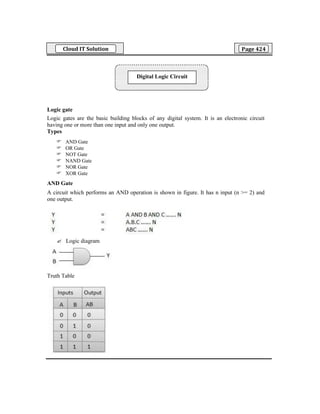
- 1. Cloud IT Solution Page 424 Logic gate Logic gates are the basic building blocks of any digital system. It is an electronic circuit having one or more than one input and only one output. Types AND Gate OR Gate NOT Gate NAND Gate NOR Gate XOR Gate AND Gate A circuit which performs an AND operation is shown in figure. It has n input (n >= 2) and one output. Logic diagram Truth Table Digital Logic Circuit
- 2. Cloud IT Solution Page 425 OR Gate A circuit which performs an OR operation is shown in figure. It has n input (n >= 2) and one output. Logic diagram Truth Table NOT Gate NOT gate is also known as Inverter. It has one input A and one output Y. Logic diagram
- 3. Cloud IT Solution Page 426 Truth Table NAND Gate A NOT-AND operation is known as NAND operation. It has n input (n >= 2) and one output. Logic diagram Truth Table NOR Gate A NOT-OR operation is known as NOR operation. It has n input (n >= 2) and one output.
- 4. Cloud IT Solution Page 427 Logic diagram Truth Table XOR Gate XOR or Ex-OR gate is a special type of gate. It can be used in the half adder, full adder and subtractor. The exclusive-OR gate is abbreviated as EX-OR gate or sometime as X-OR gate. It has n input (n >= 2) and one output. Logic diagram Truth Table
- 5. Cloud IT Solution Page 428 XNOR Gate XNOR gate is a special type of gate. It can be used in the half adder, full adder and subtractor. The exclusive-NOR gate is abbreviated as EX-NOR gate or sometime as X-NOR gate. It has n input (n >= 2) and one output Logic diagram Truth Table NAND and NOR Universal Gate NAND and NOR are called universal gates because all the other gates like and,or,not,xor and xnor can be derived from it. Any basic gate can be implemented using NAND and NOR.
- 6. Cloud IT Solution Page 429 De Morgan's Theorems De Morgan has suggested two theorems which are extremely useful in Boolean Algebra. Theorem 1 The left hand side (LHS) of this theorem represents a NAND gate with inputs A and B, whereas the right hand side (RHS) of the theorem represents an OR gate with inverted inputs.
- 7. Cloud IT Solution Page 430 This OR gate is called as Bubbled OR. Table showing verification of the De Morgan's first theorem – Theorem 2 The LHS of this theorem represents a NOR gate with inputs A and B, whereas the RHS represents an AND gate with inverted inputs.
- 8. Cloud IT Solution Page 431 his AND gate is called as Bubbled AND. Table showing verification of the De Morgan's second theorem – Half Adder Half adder is a combinational logic circuit with two inputs and two outputs. The half adder circuit is designed to add two single bit binary number A and B. It is the basic building block for addition of two single bit numbers. This circuit has two outputs carry and sum.
- 9. Cloud IT Solution Page 432 Truth Table Circuit Diagram Full Adder Full adder is developed to overcome the drawback of Half Adder circuit. It can add two one- bit numbers A and B, and carry c. The full adder is a three input and two output combinational circuit. Truth Table
- 10. Cloud IT Solution Page 433 Circuit Diagram Full adder using two half adder K-map Karnaugh introduced a method for simplification of Boolean functions in an easy way. This method is known as Karnaugh map method or K-map method. It is a graphical method, which consists of 2n cells for ‘n’ variables. Variable K-Map
- 11. Cloud IT Solution Page 434 Variable K-Map Variable K-Map Example Let us simplify the following Boolean function, f(W, X, Y, Z)= WX’Y’ + WY + W’YZ’ using K-map.
- 12. Cloud IT Solution Page 435 Simplified Boolean function is: f= WX’ + WY + YZ’ Example Let us simplify the following Boolean function, f(X,Y,Z)=∏M(0,1,2,4) using K-map. Simplified Boolean function is: f=(X+Y).(Y+Z).(Z+X)
- 13. Cloud IT Solution Page 436 Latch There are two types of memory elements based on the type of triggering that is suitable to operate it. 1. Latches 2. Flip-flops Latches operate with enable signal, which is level sensitive. Whereas, flip-flops are edge sensitive. We will discuss about flip-flops in next chapter. Now, let us discuss about SR Latch & D Latch one by one. SR latch example Flip-flops A flip-flop or latch is a circuit that has two stable states and can be used to store state information. A flip-flop is a bistable multivibrator. The circuit can be made to change state by signals applied to one or more control inputs and will have one or two outputs. It is the basic storage element in sequential logic. Flip-flops and latches are fundamental building blocks of digital electronics systems used in computers, communications, and many other types of systems There are mainly four types of flip flops that are used in electronic circuits. They are 1. The basic Flip Flop or S-R Flip Flop 2. Delay Flip Flop [D Flip Flop] 3. J-K Flip Flop 4. T Flip Flop S-R Flip Flop The SET-RESET flip flop is not designed with the help of two NOR gates and also two NAND gates. These flip flops are also called S-R Latch.
- 14. Cloud IT Solution Page 437 S-R Flip Flop using NOR Gate S-R Flip Flop using NAND Gate
- 15. Cloud IT Solution Page 438 J-K Flip Flop Difference between CISC and RISC CISC RISC It is prominent on Hardware It is prominent on the software It has high cycles per second It has low cycles per second It has transistors used for storing Instructions which are complex More transistors are used for storing memory LOAD and STORE memory to memory is induced in instructions LOAD and STORE register to register are independent It has multi-clock It has single-clock
- 16. Cloud IT Solution Page 439 1. The output of an AND gate with three inputs, A, B, and C, is HIGH when ________. A) A = 1, B = 1, C = 0 B)A = 0, B = 0, C = 0 C)A = 1, B = 1, C = 1 D)A = 1, B = 0, C = 1 2. If a 3-input NOR gate has eight input possibilities, how many of those possibilities will result in a HIGH output? A. 1 B. 2 C. 7 D. 8 3. If a signal passing through a gate is inhibited by sending a LOW into one of the inputs, and the output is HIGH, the gate is a(n): A. AND B. NAND C. NOR D. OR 4. A device used to display one or more digital signals so that they can be compared to expected timing diagrams for the signals is a: A. DMM B. spectrum analyzer C. logic analyzer D. frequency counter 5. When used with an IC, what does the term QUAD indicate? A. 2 circuits B. 4 circuits C. 6 circuits D. 8 circuits 6. The output of an OR gate with three inputs, A, B, and C, is LOW when ________. A) A = 0, B = 0, C = 0 B) A = 0, B = 0, C = 1 C) A = 0, B = 1, C = 1 D) all of the above 7. Which of the following logical operations is represented by the + sign in Boolean algebra? A. inversion B. AND C. OR D. complementation 8. Output will be a LOW for any case when one or more inputs are zero for a(n): A. OR gate B. NOT gate C. AND gate D. NOR gate 9. How many pins does the 4049 IC have? A. 14 B. 16 C. 18 D. 20 10. Which of the following choices meets the minimum requirement needed to create specialized waveforms that are used in digital control and sequencing circuits? A. basic gates, a clock oscillator, and a repetitive waveform generator B. basic gates, a clock oscillator, and a Johnson shift counter C. basic gates, a clock oscillator, and a DeMorgan pulse generator D. basic gates, a clock oscillator, a repetitive waveform generator, and a Johnson shift counter 1 2 3 4 5 6 7 8 9 10 C A B C B A C C B A Model Test Answer Model Test