
Recommended
More Related Content
What's hot
What's hot (20)
Similar to RF Based Home Automation System
Similar to RF Based Home Automation System (20)
Recently uploaded
Recently uploaded (20)
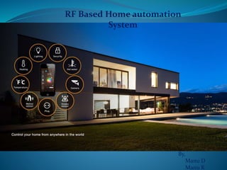
RF Based Home Automation System
- 1. RF Based Home automation System By, Manu D Manu K
- 2. Introduction RF based Home Automation System As the technologies are rapidly advancing that affects the human daily lives more flexible, particularly in controlling home appliances. Electrical installations are the heart of every building, therefore intelligent building control absolutely ensures the safety and efficient control and eventually saves the electric power consumption and human energy. Home automation system does the operations like lighting control and regulation, regulating HVAC (Heating, Ventilation and Air Conditioning) equipment’s, energy and load management, security and monitoring, audio/ video systems, HMI’s and other control tasks.
- 3. Functional Description: Presently, conventional wall switches located in different parts of the house makes it difficult for the user to go near them to operate. In order to achieve this, a RF remote is Transfer a signal which sends ON/OFF commands to the receiver where loads are connected. By operating the specified remote switch on the transmitter, the loads can be turned ON/OFF remotely through wireless technology. This circuit utilizes the RF module (Tx/Rx) for making a wireless remote, which could be used to drive an output from a distant place. RF module, as the name suggests, uses radio frequency to send signals . These signals are transmitted at a particular frequency and a baud rate.
- 5. Components Required RF Transmitter RF Receiver Ic HT12d IC HT12e Resistor 750k -2 Resistor 33k -2 Resistor 1k -8 Transistor BC547 – 8 IC socket 18 pin-4 3 pin switch Relay – 8 PCB 2 LED 2 Power Supply 12v Ic 7408(Regulator) Connecting Wires with Soldering Kit
- 6. Features Range in open space(Standard Conditions) : 100 Meters RX Receiver Frequency : 433 MHz RX Typical Sensitivity : 105 Dbm RX Supply Current : 3.5 mA RX IF Frequency : 1MHz Low Power Consumption Easy For Application RX Operating Voltage : 5V TX Frequency Range : 433.92 MHz TX Supply Voltage : 3V ~ 6V TX Out Put Power : 4 ~ 12 Dbm RF Transmitter and Receiver
- 7. Encoder ic pin mode Pin No Function Name 1 8 bit Address pins for input A0 2 A1 3 A2 4 A3 5 A4 6 A5 7 A6 8 A7 9 Ground (0V) Ground 10 4 bit Data/Address pins for input AD0 11 AD1 12 AD2 13 AD3 14 Transmission enable; active low TE 15 Oscillator input Osc2 16 Oscillator output Osc1 17 Serial data output Output 18 Supply voltage; 5V (2.4V- 12V) Vcc
- 8. Decoder IC pin mode
- 10. Applications Light Control Fan Control Electrical Equipment Control RF car control Etc..