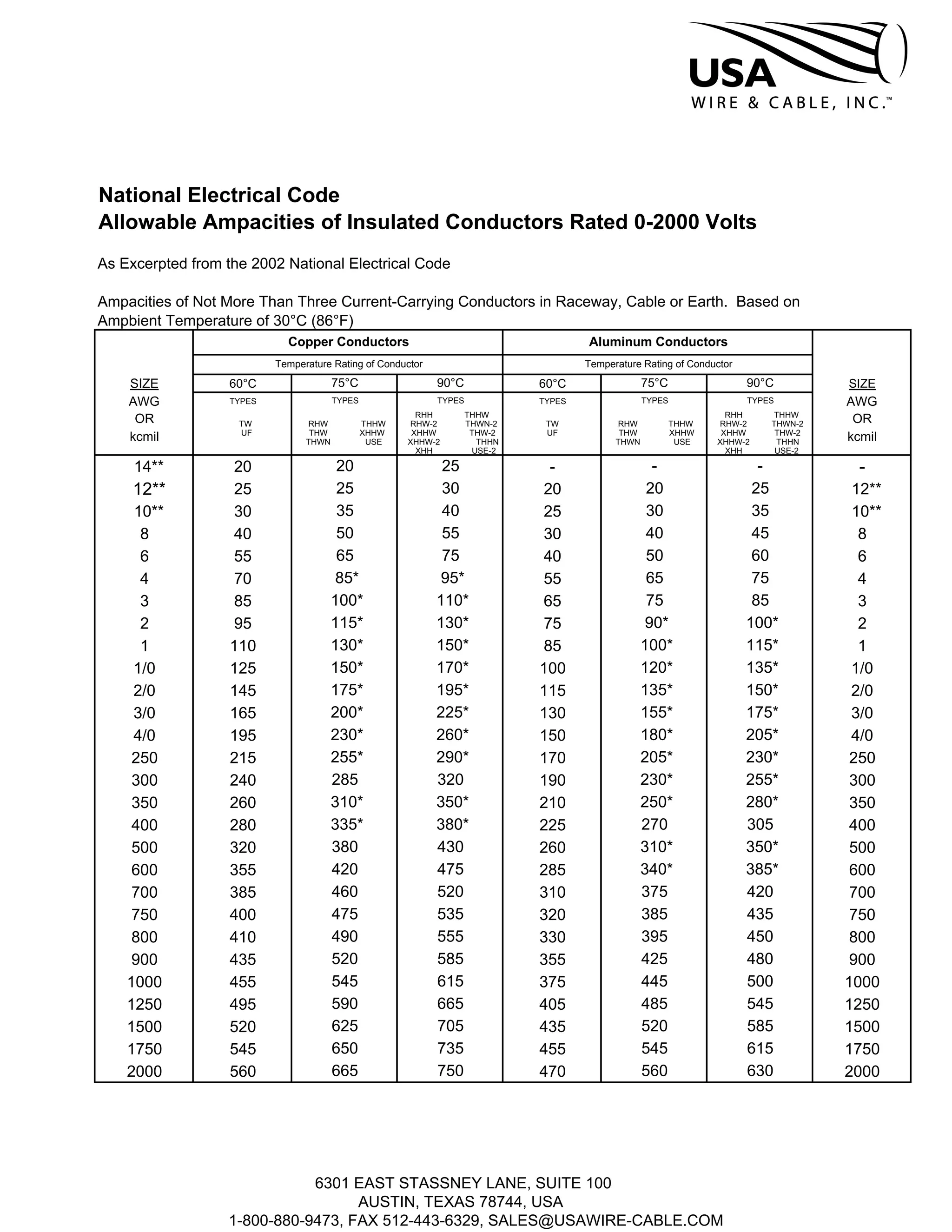
National Electrical Code
Allowable Ampacities of Insulated Conductors Rated 0-2000 Volts
As Excerpted from the 2002 National Electrical Code
Ampacities of Not More Than Three Current-Carrying Conductors in Raceway, Cable or Earth. Based on
Ampbient Temperature of 30°C (86°F)
Copper Conductors Aluminum Conductors
Temperature Rating of Conductor Temperature Rating of Conductor
SIZE 60°C 75°C 90°C 60°C 75°C 90°C SIZE
AWG TYPES TYPES TYPES TYPES TYPES TYPES AWG
OR RHH THHW RHH THHW
ORTW RHW THHW RHW-2 THWN-2 TW RHW THHW RHW-2 THWN-2
kcmil UF THW XHHW XHHW THW-2 UF THW XHHW XHHW THW-2
kcmilTHWN USE XHHW-2 THHN THWN USE XHHW-2 THHN
XHH USE-2 XHH USE-2
14** 20 20 25 - - - -
12** 25 25 30 20 20 25 12**
10** 30 35 40 25 30 35 10**
8 40 50 55 30 40 45 8
6 55 65 75 40 50 60 6
4 70 85* 95* 55 65 75 4
3 85 100* 110* 65 75 85 3
2 95 115* 130* 75 90* 100* 2
1 110 130* 150* 85 100* 115* 1
1/0 125 150* 170* 100 120* 135* 1/0
2/0 145 175* 195* 115 135* 150* 2/0
3/0 165 200* 225* 130 155* 175* 3/0
4/0 195 230* 260* 150 180* 205* 4/0
250 215 255* 290* 170 205* 230* 250
300 240 285 320 190 230* 255* 300
350 260 310* 350* 210 250* 280* 350
400 280 335* 380* 225 270 305 400
500 320 380 430 260 310* 350* 500
600 355 420 475 285 340* 385* 600
700 385 460 520 310 375 420 700
750 400 475 535 320 385 435 750
800 410 490 555 330 395 450 800
900 435 520 585 355 425 480 900
1000 455 545 615 375 445 500 1000
1250 495 590 665 405 485 545 1250
1500 520 625 705 435 520 585 1500
1750 545 650 735 455 545 615 1750
2000 560 665 750 470 560 630 2000
6301 EAST STASSNEY LANE, SUITE 100
AUSTIN, TEXAS 78744, USA
1-800-880-9473, FAX 512-443-6329, SALES@USAWIRE-CABLE.COM
National Electrical Code
Allowable Ampacities of Insulated Conductors
Rated 0-2000 Volts
As Excerpted from the 2002 National Electrical Code
(Notes to Accompany Table)
NOTE 1:
Temp. Type and Location
Type TW, wet or dry
Type UF, wet or dry, or corrosive
locations
Types RHW, THW, THWN, USE,
THHW, XHHW, wet or dry
Types RHH, THHN, XHHW, XHH,

dry and damp locations.

Type THHW, dry locations.

Types THWN-2, XHHW-2,

THW-2, RHW-2, USE-2, wet or dry

NOTE 2:
Max. size of Type UF is 4/0 AWG.
Max. size of Types THWN and THHN ­
1000 kcmil
Max. size of Type THHW is 1000 kcmil
NOTE 3:
The allowable values in the Ampacity
Table are based on temperature alone and
do not take voltage drop into consideration.
** Unless specifically permitted in Section
240.4(E) through (G), the overcurrent
protection shall not exceed 15 amperes
for 14 AWG, 20 amperes for 12 AWG, and
30 amperes for 10 AWG copper; or 15
amperes for 12 AWG and 25 amoeres for
10 AWG aluminum after any correction
factors Tor ambient temperature and
number of conductors have been applied.
NOTE 4:
Where the number of current-carrying conductors in a raceway
or cable exceeds three, or where single conductors or multi­
conductor cables are stacked or bundled longer than 24 inches
without maintaining spacing and are not installed in raceways,
the allowable ampacity of each conductor shall be reduced as
shown in the following table:
Percent of Values inNumber of
Table as Adjusted forCurrent Carrying
Ambient Temp.,Conductors
if Necessary
4 thru 6

7 thru 9

10thru20

21 thru 30

31 thru 40

41 and above*

80
70
50
45
40
35
The above derating factors do not apply to conductors in nipples
having a length not exceeding 24 inches.
NOTE 5:
For ambient temperatures other than 30°C, multiply the allowable
ampacities by the appropriate factor shown below:
Ambient
Temperature
Conductor Temperature
Ambient
Temperature
°C 60°C 75°C 90°C
of
21 - 25 1.08 1.05 1.04 70 -77
26 - 30 1.00 1.00 1.00 78 - 86
31 - 35 .91 .94 .96 87 - 95
36 - 40 .82 .88 .91 96 - 104
41 - 45 .71 .82 .87 105· 113
46 - 50 .58 .75 .82 114 - 122
51 - 55 .41 .67 .76 123 - 131
56 - 60 .58 .71 132 - 140
61 - 70 .33 .58 141 - 158
71 - 80 .41 159 - 176
*For dwelling units, conductors, as listed below, shall be permitted as
120/240 volt, 3 wire, single phase service-entrance conductors, service
lateral conductors and feeder conductors that serve as the main power feeder
to a dwelling unit and are installed in raceway or cable with or without an
equipment grounding conductor. For application of this section, the main
power feeder shall be the feeder(s) between the main disconnect and the
lighting and appliance branch-circuit panel board(s) and the feeder
conductors to a dwelling unit shall not be required to be larger than their
service entrance conductors. The grounded conductor shall be permitted to
be smaller than the ungrounded conductors provided the requirements of
Sections 215.2, 220.22 and 230.42 are met.
RHH , RHW, THHW, THW, THWN, THHN, XHHW, USE,
RHW-2, THW-2, THWN-2, XHHW-2, SE, USE-2
Copper Aluminum
AWG AWG Service or Feeder
or kcmil or kcmil Rating (Amperes)
4 1002
3 1101
2 1251/0
1 1502/0
1/0 1753/0
2/0 2004/0
3/0 225250
4/0 250300
250 300350
350 350500
400 400600
6301 EAST STASSNEY LANE, SUITE 100
AUSTIN, TEXAS 78744, USA
1-800-880-9473, FAX 512-443-6329, SALES@USAWIRE-CABLE.COM

Nec ampacities

  • 1.
    National Electrical Code AllowableAmpacities of Insulated Conductors Rated 0-2000 Volts As Excerpted from the 2002 National Electrical Code Ampacities of Not More Than Three Current-Carrying Conductors in Raceway, Cable or Earth. Based on Ampbient Temperature of 30°C (86°F) Copper Conductors Aluminum Conductors Temperature Rating of Conductor Temperature Rating of Conductor SIZE 60°C 75°C 90°C 60°C 75°C 90°C SIZE AWG TYPES TYPES TYPES TYPES TYPES TYPES AWG OR RHH THHW RHH THHW ORTW RHW THHW RHW-2 THWN-2 TW RHW THHW RHW-2 THWN-2 kcmil UF THW XHHW XHHW THW-2 UF THW XHHW XHHW THW-2 kcmilTHWN USE XHHW-2 THHN THWN USE XHHW-2 THHN XHH USE-2 XHH USE-2 14** 20 20 25 - - - - 12** 25 25 30 20 20 25 12** 10** 30 35 40 25 30 35 10** 8 40 50 55 30 40 45 8 6 55 65 75 40 50 60 6 4 70 85* 95* 55 65 75 4 3 85 100* 110* 65 75 85 3 2 95 115* 130* 75 90* 100* 2 1 110 130* 150* 85 100* 115* 1 1/0 125 150* 170* 100 120* 135* 1/0 2/0 145 175* 195* 115 135* 150* 2/0 3/0 165 200* 225* 130 155* 175* 3/0 4/0 195 230* 260* 150 180* 205* 4/0 250 215 255* 290* 170 205* 230* 250 300 240 285 320 190 230* 255* 300 350 260 310* 350* 210 250* 280* 350 400 280 335* 380* 225 270 305 400 500 320 380 430 260 310* 350* 500 600 355 420 475 285 340* 385* 600 700 385 460 520 310 375 420 700 750 400 475 535 320 385 435 750 800 410 490 555 330 395 450 800 900 435 520 585 355 425 480 900 1000 455 545 615 375 445 500 1000 1250 495 590 665 405 485 545 1250 1500 520 625 705 435 520 585 1500 1750 545 650 735 455 545 615 1750 2000 560 665 750 470 560 630 2000 6301 EAST STASSNEY LANE, SUITE 100 AUSTIN, TEXAS 78744, USA 1-800-880-9473, FAX 512-443-6329, SALES@USAWIRE-CABLE.COM
  • 2.
    National Electrical Code AllowableAmpacities of Insulated Conductors Rated 0-2000 Volts As Excerpted from the 2002 National Electrical Code (Notes to Accompany Table) NOTE 1: Temp. Type and Location Type TW, wet or dry Type UF, wet or dry, or corrosive locations Types RHW, THW, THWN, USE, THHW, XHHW, wet or dry Types RHH, THHN, XHHW, XHH, dry and damp locations. Type THHW, dry locations. Types THWN-2, XHHW-2, THW-2, RHW-2, USE-2, wet or dry NOTE 2: Max. size of Type UF is 4/0 AWG. Max. size of Types THWN and THHN ­ 1000 kcmil Max. size of Type THHW is 1000 kcmil NOTE 3: The allowable values in the Ampacity Table are based on temperature alone and do not take voltage drop into consideration. ** Unless specifically permitted in Section 240.4(E) through (G), the overcurrent protection shall not exceed 15 amperes for 14 AWG, 20 amperes for 12 AWG, and 30 amperes for 10 AWG copper; or 15 amperes for 12 AWG and 25 amoeres for 10 AWG aluminum after any correction factors Tor ambient temperature and number of conductors have been applied. NOTE 4: Where the number of current-carrying conductors in a raceway or cable exceeds three, or where single conductors or multi­ conductor cables are stacked or bundled longer than 24 inches without maintaining spacing and are not installed in raceways, the allowable ampacity of each conductor shall be reduced as shown in the following table: Percent of Values inNumber of Table as Adjusted forCurrent Carrying Ambient Temp.,Conductors if Necessary 4 thru 6 7 thru 9 10thru20 21 thru 30 31 thru 40 41 and above* 80 70 50 45 40 35 The above derating factors do not apply to conductors in nipples having a length not exceeding 24 inches. NOTE 5: For ambient temperatures other than 30°C, multiply the allowable ampacities by the appropriate factor shown below: Ambient Temperature Conductor Temperature Ambient Temperature °C 60°C 75°C 90°C of 21 - 25 1.08 1.05 1.04 70 -77 26 - 30 1.00 1.00 1.00 78 - 86 31 - 35 .91 .94 .96 87 - 95 36 - 40 .82 .88 .91 96 - 104 41 - 45 .71 .82 .87 105· 113 46 - 50 .58 .75 .82 114 - 122 51 - 55 .41 .67 .76 123 - 131 56 - 60 .58 .71 132 - 140 61 - 70 .33 .58 141 - 158 71 - 80 .41 159 - 176 *For dwelling units, conductors, as listed below, shall be permitted as 120/240 volt, 3 wire, single phase service-entrance conductors, service lateral conductors and feeder conductors that serve as the main power feeder to a dwelling unit and are installed in raceway or cable with or without an equipment grounding conductor. For application of this section, the main power feeder shall be the feeder(s) between the main disconnect and the lighting and appliance branch-circuit panel board(s) and the feeder conductors to a dwelling unit shall not be required to be larger than their service entrance conductors. The grounded conductor shall be permitted to be smaller than the ungrounded conductors provided the requirements of Sections 215.2, 220.22 and 230.42 are met. RHH , RHW, THHW, THW, THWN, THHN, XHHW, USE, RHW-2, THW-2, THWN-2, XHHW-2, SE, USE-2 Copper Aluminum AWG AWG Service or Feeder or kcmil or kcmil Rating (Amperes) 4 1002 3 1101 2 1251/0 1 1502/0 1/0 1753/0 2/0 2004/0 3/0 225250 4/0 250300 250 300350 350 350500 400 400600 6301 EAST STASSNEY LANE, SUITE 100 AUSTIN, TEXAS 78744, USA 1-800-880-9473, FAX 512-443-6329, SALES@USAWIRE-CABLE.COM