SlideShare a Scribd company logo
1 of 26
Download to read offline
Review Article
Rehabilitative and assistive wearable
mechatronic upper-limb devices:
A review
Tyler Desplenter1
, Yue Zhou2
, Brandon PR Edmonds2
,
Myles Lidka1
, Allison Goldman1
and Ana Luisa Trejos1,2,3
Abstract
Recently, there has been a trend toward assistive mechatronic devices that are wearable. These devices provide the
ability to assist without tethering the user to a specific location. However, there are characteristics of these devices that
are limiting their ability to perform motion tasks and the adoption rate of these devices into clinical settings. The
objective of this research is to perform a review of the existing wearable assistive devices that are used to assist with
musculoskeletal and neurological disorders affecting the upper limb. A review of the existing literature was conducted
on devices that are wearable, assistive, and mechatronic, and that provide motion assistance to the upper limb. Five
areas were examined, including sensors, actuators, control techniques, computer systems, and intended applications.
Fifty-three devices were reviewed that either assist with musculoskeletal disorders or suppress tremor. The general
trends found in this review show a lack of requirements, device details, and standardization of reporting and evaluation.
Two areas to accelerate the evolution of these devices were identified, including the standardization of research, clinical,
and engineering details, and the promotion of multidisciplinary culture. Adoption of these devices into their intended
application domains relies on the continued efforts of the community.
Keywords
Wearable, assistive, upper limb, mechatronic systems, rehabilitation, tremor suppression
Date received: 29 January 2019; accepted: 11 March 2020
Introduction
Technological research and increasing demands for
motion assistance are driving societies towards a
world in which this demand can be met through assis-
tive mechatronic devices. According to the Global
Burden of Disease study in 2016, approximately
2.5 billion and 1.2 billion people suffer from neurolog-
ical disorders (NDs) and musculoskeletal disorders
(MSDs), respectively.1
Many of these disorders will
require some form of rehabilitation, motion training,
or motion assistance for at least a portion of time after
the onset of the disorders. For other progressive disor-
ders, the dependence on assistance with activities of
daily living (ADLs) will increase over time. Studies of
the economic burden of MSDs in many countries have
shown yearly costs of approximately $33.5 billion in
Canada,2
$231 billion in the USA,3
$1.3 billion in
Chile,4
and $15.6 billion in Sweden.5
These burdens
will continue to grow as the population grows and
the proportion of the population needing motion assis-
tance increases. Meeting this demand with traditional
intervention strategies may become unfeasible as the
demand continues to grow at a faster pace than avail-
able resources.
The potential for assistive upper-limb devices to pro-
vide improved quality of life to humans has been
1
Department of Electrical and Computer Engineering, University of
Western Ontario, London, Canada
2
School of Biomedical Engineering, University of Western Ontario,
London, Canada
3
Lawson Health Research Institute, London, Canada
Corresponding author:
Ana Luisa Trejos, University of Western Ontario, 1151 Richmond St,
Amit Chakma Engineering Building, London, Ontario N6A 5B9, Canada.
Email: atrejos@uwo.ca
Journal of Rehabilitation and Assistive
Technologies Engineering
Volume 7: 1–26
! The Author(s) 2020
Article reuse guidelines:
sagepub.com/journals-permissions
DOI: 10.1177/2055668320917870
journals.sagepub.com/home/jrt
Creative Commons Non Commercial CC BY-NC: This article is distributed under the terms of the Creative Commons Attribution-
NonCommercial 4.0 License (https://creativecommons.org/licenses/by-nc/4.0/) which permits non-commercial use, reproduction and dis-
tribution of the work without further permission provided the original work is attributed as specified on the SAGE and Open Access pages (https://us.
sagepub.com/en-us/nam/open-access-at-sage).
expanding the number of research endeavors in this
field over the last few decades. This increase in research
comes as the earlier devices have been shown to be
effective tools for assistance in clinical trials.6,7
The
number of devices entering this research community
has generated many reviews. In 2011, Gopura et al.
provide a brief examination of upper-limb exoskele-
tons, categorized by actuation type.8
Lo and Xie inves-
tigated existing upper-limb exoskeleton systems with a
summarization of the key challenges faced by these
systems in 2012.9
In 2014, Maciejasz et al. conducted
an extensive review of upper-limb devices, which fea-
tures over 120 rehabilitation systems.10
This review
examined the combined contributions of portable and
non-portable devices and revealed the shift toward
wearable devices, although many of the systems are
non-portable. Furthermore, this study is missing a
detailed discussion of the sensing and computer sys-
tems, which are critical components of mechatronic
systems. The review presented here aims to comple-
ment the one conducted by Maciejasz et al. by focusing
on portable devices and including additional areas of
review.
Increasing the wearability and portability comes
from improvements, such as weight, volume and
power reduction, increasing accuracy, optimizing com-
putational resources, and estimating uncertainties.
These improvements require further research efforts
in sensor, actuator, control, and computer systems.
The objective of this review is to explore the existing
research contributions in the area of wearable assistive
mechatronic devices for the upper limb. First, an over-
view of the state-of-the-art of these devices for the
upper limb will be presented. Next, a detailed analysis
of five key areas, sensing, actuation, control, computa-
tion, and applications, will provide evidence of suc-
cesses and limitations of existing technologies and
methods. Finally, the challenges faced by this research
community will be discussed, and future directions
identified.
Review criteria and methods
Innovation of wearable assistive mechatronic devices is
out-pacing the standardization of terminology of the
research areas involved in their development. As a
result, terms, such as exoskeleton, robot, manipulator,
and mechatronic device are being used interchangeably
making it difficult to dissect these fields of engineering.
In order to eliminate this confusion, the following def-
initions of the criteria are proposed, in order to clarify
the review and the distinctions between devices. In this
review, devices are chosen based on their fulfillment of
the following four criteria: wearable, assistive, mecha-
tronic, and for the upper limb. Wearable is identified as
the property that the base of a manipulator originates
from one or more attachment points on the human
body. This distinction is made to exclude exoskeleton-
or end-effector-based systems where the base of the
manipulator originates from attachment points in the
environment, such as the floor or wall, and, therefore,
limits the wearability of the system. Furthermore, this
definition includes devices that are intended to be wear-
able, but may not be fully portable due to limitations in
their components. Assistive implies that the device is
able to provide assistance to the user during comple-
tion of motion tasks. A distinction made in this review
is that assistance is viewed as the generation of forces to
either support a desired motion, such as during reha-
bilitative interventions, or to suppress an undesired
motion, such as in tremor suppression. A mechatronic
device encompasses systems that are comprised of
mechanical and electrical components, and has been
programmed to automatically complete complex
tasks, such as assisting with human motion. The four
major components of mechatronic system are the
mechanical, electrical and electronic, computer, and
control systems. Any devices or systems that fit these
criteria and are intended to assist with upper-limb
motion, including the thoracic spine, cervical spine,
shoulder, elbow, wrist, or hand, were candidates for
this review.
In this review, the sensing, actuation, control, and
computer systems of these devices will be examined to
identify the state-of-the-art and challenges facing their
future. Sensors and actuators are required to measure
and manipulate biological properties of the user.
Control systems are needed to ensure proper behavior
of the device. Communication and processing of bio-
logical, environmental, and device information is facil-
itated through computer systems. Although all of these
sub-systems may not be needed for the devices to be
classified as a mechatronic system, these sub-systems
have been identified as necessary to provide motion
assistance to humans. Since it may not be possible to
fully describe the details of all sub-systems in a single
manuscript, an article must contain at least brief
descriptions of three of the four sub-systems to be
included in this review. No specific inclusion criteria
were used to narrow the scope of the application
domains that are targeted by these devices.
The review was conducted by examining the IEEE
Xplore, Google Scholar, ACM Digital Library,
Scopus, Inspec, and Compex databases for relevant
articles. The databases were searched using various
combinations of the keywords: assistive, device, exo-
skeleton, mechatronic, portable, rehabilitation, robot,
tremor, and wearable. The initial search resulted in
90 articles that were considered based on keyword
matches, abstract content, and brief review of the
2 Journal of Rehabilitation and Assistive Technologies Engineering
article. The next step involved reviewing each article to
determine whether or not it met the review criteria. In
order to be included in this review, each study had to
include a device that met both the definition criteria
and the sub-system detail criteria discussed above.
Individual authors were assigned to review a portion
of the 90 articles. If an author could not determine
whether or not inclusion criteria had been met, all
authors would review the article and vote on its inclu-
sion. This process resulted in a total of 64 articles that
were found to meet the criteria and be considered as
part of this review.
Commercially available devices
To date, only one device fits our review criteria and is
commercially available. The MyoPro is a wearable
assistive device developed for assistance for individuals
suffering from NDs, such as brachial plexus injury or
stroke.11,12
The most recent version of the MyoPro uses
electromyography (EMG) sensors to detect muscle
activity from both the elbow and forearm flexors and
extensors in order to assist with elbow flexion–exten-
sion and grasping. The sensing, actuation, control, and
computer systems are contained within the device
making it fully portable and wireless during operation.
Multiple clinical studies using the MyoPro to assist
with rehabilitation activities for individuals suffering
from stroke conclude that rehabilitation using this
device is as effective as traditional manual therapy
and improves performance during functional tasks
when worn.11,13–15
The successes of the MyoPro sup-
port further inquiry into these technologies and show a
promising future for wearable assistive devices.
State-of-the-art: Devices in the literature
The goal of this review is to answer the question: what
is the state-of-the-art in wearable assistive mechatronic
devices for the upper limb? Besides the MyoPro elbow
device, the state of the wearable assistive devices lies
within the research realm. A total of 53 wearable assis-
tive mechatronic upper-limb devices have been identi-
fied from the literature. The majority of the articles
reviewed were motivated by disorders such as stroke,
Parkinson’s disease, essential tremor, spinal cord
injury, arthritis, and post-surgical or post-traumatic
nerve damage. However, other disorders mentioned
in the literature include cerebral palsy, chronic carpel
tunnel syndrome, muscular atrophy, multiple sclerosis,
congenital disorders, and osteoarthritis. No wearable
assistive devices were found that meet the criteria and
assist with thoracic or cervical spine motion. Therefore,
these two body segments will not be discussed further.
The complexity of the technology and the human
body has caused an expansion of research into these
devices over the last decade. In fact, 54% of the articles
reviewed were published within the last five years. The
multidisciplinary nature of these devices coupled with
the immaturity of this field has led to diversity of the
technologies used. An overview of the major technolo-
gies used in these devices can be found in Table 1.
Devices in this table have been categorized by the
joints they actuate. Brief details about their supported
motions, sensed quantities, actuation systems, control
quantities, and application type are listed.
Overall, there are a few trends worth noting about
the state-of-the-art. First, the bulk of these devices are
wearable, but not fully portable. In many cases, either a
portion or all of the actuation system, power supply, or
communication and control cables tether these devices
to a location. Second, the majority of the devices in this
review focus on the motion of a single arm segment
(87% of devices) with opening and/or closing of the
hand and fingers being the largest focus (51% of devi-
ces). Improving the movement of even one segment in
the upper limb can translate into a better quality of life
for those suffering from the disorders. The single-
segment approach to the design of these devices has a
higher likelihood of finding solutions and, therefore,
getting to market and creating a social benefit. Lastly,
it should be noted that few clinical studies have been
performed on any of the reviewed devices. The devices
are still in development and require vigorous testing to
ensure human safety. Therefore, the research areas sur-
rounding wearable assistive technologies have many
questions that still need to be answered.
The devices considered for this review have been
examined based on the topics of sensing, actuation,
control, computation, and applications. The major
technologies and techniques from each of these topics
are discussed in the following sections.
Sensing
Sensors are a major component within wearable assis-
tive devices, as they are able to detect changes within
the device, the manner in which the user interacts with
it, or the environment. Sensing can be used to influence
the system’s behavior, allowing it to respond appropri-
ately to user’s needs and fulfill the device’s purpose.
In 77% of the devices, biological signals were mea-
sured and used towards control of the system. These
devices can be further sorted into physiological signals,
which are electrically representative signals of internal
physiological processes of the human body, and biome-
chanical signals, which are signals measuring the out-
wards motion performed by the human body, such as
joint position and exerted force. The use of sensor
Desplenter et al. 3
Table
1.
An
overview
of
existing
wearable
assistive
mechatronic
devices.
Author
(Reference)
Supported
movements
Sensed
quantities
Actuation
Controlled
quantities
Type
of
assistance
Shoulder,
elbow,
and
wrist
Sugar
et
al.
16
Shoulder-F
Elbow-F,
S
Wrist-E
Position,
pressure
Pneumatic
actuator
Torque
Support
Shoulder
and
elbow
Brackbill
et
al.
17
Shoulder-FE,
AbAd,
IE
Elbow-FE
Not
listed
Electric
motor
Position
Support
Lessard
et
al.
18
Shoulder-Ab
Elbow-FE,
PS
Position,
heart
rate
Electric
motor
Torque
Support
Elbow
and
wrist
Rocon
et
al.
19
Elbow-FE,
PS
Wrist-FE
Velocity,
force
Electric
motor
Torque,
velocity
Suppression
Ueda
et
al.
20
Elbow-FE,
PS
Wrist-FE,
RU
Position,
EMG
Pneumatic
actuator
Force
Support
Xiao
et
al.
21
Elbow-FE,
PS
Wrist-FE,
RU
EEG
Electric
motor
Position
Support
Elbow
Ando
et
al.
22
Elbow-FE
EMG
Electric
motor
Torque
Suppression
Vaca
Benitez
et
al.
23
Elbow-FE
EMG,
position,
torque
Electric
motor
Torque
Support
Desplenter
et
al.
24
Elbow-FE
EMG
Electric
motor
Velocity
Support
Herrnstadt
and
Menon
25
Elbow-FE
Position,
velocity
Electromagnetic
brake
Torque
Suppression
Kim
et
al.
26
Elbow-FE
EMG,
pressure
Pneumatic
actuator
Torque
Support
KleinJan
27
Elbow-FE
Position
SMA
Torque
Support
Kyrylova
28
Elbow-FE
EMG,
position
Electric
motor
Position,
velocity
Support
Looned
et
al.
29
Elbow-FE,
PS
EEG,
position
Electric
motor
Torque
Support
Pylatiuk
et
al.
30
Elbow-FE
EMG,
position,
pressure
Hydraulic
actuator
Force
Support
Ren
et
al.
31
Elbow-FE
Position
Electric
motor
Torque
Support
Stein
et
al.,
11
McBean
and
Narendran
12
Elbow-FE
EMG
Electric
motor
Position
Support
Tang
et
al.
32
Elbow-FE
Position,
EMG
Pneumatic
actuators
Position
Support
Vanderniepen
et
al.
33
Elbow-FE
Not
listed
Electric
motor
Torque
Support
Wang
and
Huang
34
Elbow-FE
Position,
EMG
Electric
motors
Position
Support
Wrist
Andrikopoulos
et
al.
35
Wrist-FE,
RU
Position
Pneumatic
actuators
Position
Support
Higuma
et
al.
36
Wrist-FE,
RU
Not
listed
Electric
motor
Torque
Support
Kazi
et
al.
37
Wrist-FE
Acceleration
Piezoelectric
actuator
Acceleration
Suppression
Loureiro
et
al.
38
Wrist-FE
Position
MRF
actuator
Position
Suppression
Taheri
39
Wrist-FE,
RU
Not
listed
Pneumatic
actuator
Torque
Suppression
Xiao
and
Menon
40
Wrist-FE,
RU
EMG,
torque
Electric
motor
Torque,
position
Support
Wrist
and
hand
Zhou
et
al.
41
Wrist-FE
Finger-FE
Thumb-FE
Position,
velocity
Electric
motor
Position
Suppression
Hand
Al-Fahaam
et
al.
42
Fingers/Thumb-FE
Force,
position,
EMG
Pneumatic
actuator
Force
Support
Allotta
et
al.
43–45
Fingers-FE
Not
listed
Electric
motor
Velocity
Support
(continued)
4 Journal of Rehabilitation and Assistive Technologies Engineering
Table
1.
Continued
Author
(Reference)
Supported
movements
Sensed
quantities
Actuation
Controlled
quantities
Type
of
assistance
Arata
et
al.
46
Fingers-FE
EMG,
position
LEA
Force
Support
Aubin
et
al.
47
Thumb-FE,
AbAd
Position
Electric
motor
Position
Support
Burton
et
al.
48
Fingers-FE
Thumb-FE
Position
Pneumatic
actuator
Position
Support
Cao
and
Zhang
49
Fingers-FE
Thumb-FE
EMG
Electric
motor
Velocity
Support
Cempini
et
al.
50
Finger-FE
Not
listed
Electric
motor
Torque
Support
Chiri
et
al.
51,52
Finger-E
Position
Electric
motor
Position
Support
Delph
et
al.
53
Fingers-FE
Thumb-FE
EMG
Electric
motor
Position,
force
Support
Fok
et
al.
54
Fingers-FE
EEG
LEA
Position
Support
Goutam
and
Aw
55
Finger-F
Force
LEA
Force
Support
Hadi
et
al.
56
Fingers-F,
Thumb-F
Force
SMA
Force
Support
In
et
al.
57,58
Fingers-FE
Thumb-FE
EMG,
force,
position
Electric
motor
Force
Support
Iqbal
et
al.
59–61
Finger-FE
Thumb-FE
Position,
force
Electric
motor
Position
Support
Iqbal
et
al.
62
Fingers-FE
Thumb-FE
Position,
force
Electric
motor
Not
listed
Support
Kang
et
al.
63
Fingers-FE
Thumb-FE
Not
listed
Electric
motor
Force
Support
Matheson
and
Brooker
64
Fingers-FE
Force
Pneumatic
actuators
Force
Support
Mulas
et
al.
65
Fingers-
F
Thumb-F
EMG
Electric
motor
Velocity
Support
Nycz
et
al.
66
Fingers-FE
Position
LEA
Position
Support
Polygerinos
et
al.
67
Fingers-FE
Thumb-FE
Position
Hydraulic
actuator
Force
Support
Saharan
et
al.
68
Fingers-FE
Thumb-FE
Position
TCA
Position
Support
Sandoval-Gonzalez
et
al.
69
Finger-FE
Thumb-FE
Position,
force
Electric
motor
Position,
force
Support
Tong
et
al.
70,71
Fingers-FE
Thumb-FE
EMG
LEA
Velocity
Support
Xing
et
al.
72–74
Finger-FE
Position
Pneumatic
actuator
Position
Support
Yap
et
al.
75,76
Fingers-FE
Thumb-FE
EMG,
gesture
Pneumatic
actuator
Force
Support
Yun
et
al.
77
JRTJ2000120x.png
Fingers-
FE
Thumb-FE
class¼“pic-halign”
Not
listed
Pneumatic
actuator
Force
Support
F:
flexion;
E:
extension;
P:
pronation;
S:
supination;
I:
internal
rotation;
E:
external
rotation;
Ab:
abduction;
Ad:
adduction;
R:
radial
deviation;
U:
ulnar
deviation;
EMG:
electromyography;
EEG:
electro-
encephalography;
MRF:
magnetorheological
fluid;
SMA:
smart
material
actuator;
TCA:
twisted
coiled
actuator;
LEA:
linear
electric
actuator.
Desplenter et al. 5
information collected from the actuation system to
provide system feedback was found in 36% of devices.
It is also common to use sensors external to the wear-
able device to collect data during the experimentation
process. However, this does not contribute to the real-
time control of the device. Within this section, the sens-
ing system will refer to the actual sensor itself and the
pre-processing required for the signal to be usable by
the control system, this includes additional circuitry
required for sensor functionality, filtering, amplifica-
tion, and rectification of the signal. A visual depiction
of how the sensing modalities of the reviewed devices
are distributed is shown in Figure 1.
Physiological sensing. Within wearable assistive devices,
physiological signal-based sensing is often used to
detect signals indicative of a user’s motion or force
intention. For situations where the user desires to
move but is unable to do so, such as nerve or muscular
damage, sensing of physiological signals is crucial.
From the 23 devices reviewed that incorporate physio-
logical sensing:
• 19 (82.6%) use EMG signals, which measure electri-
cal activity of muscles,
• 3 (13%) use electroencephalogram (EEG) signals,
which measure electrical activity of the brain,
• and 1 (0.4%) uses EMG and muscle–force stiffness
signals, which measure the change in force of a
muscle as it contracts.26
The physiological signals collected are often of a
small amplitude, susceptible to noise, and can be chal-
lenging to classify. Still, 43% of the devices reviewed
have incorporated this type of sensor-based feedback.
EMG. EMG is the measurement of the electrical
potentials produced at the muscle.78
These myoelectric
signals are a result of the person’s intention to move. In
wearable applications, surface electromyography
(sEMG) is the method typically used to obtain data.
sEMG electrodes are placed onto the surface of the
skin and electrically coupled to the action potential
signals of the muscle, resulting in a voltage measure-
ment of the muscle activity.
All of the devices employing sEMG to collect muscle
signals using gelled contact electrodes, abide by Surface
ElectroMyoGraphy for the Non-Invasive Assessment
of Muscles standards.79
This standard ensures electro-
mechanical stability and reduces noise. The electrodes
are placed in a bipolar configuration, such that two
electrode sites are placed over each muscle of interest.
The two channels undergo differential amplification to
eliminate the common-mode signal, allowing the
changes in muscle activity to be more evident. Use of
hydrogel ensures that the electrode properly adheres to
the arm, preventing sensor movement and motion
artifacts.
In each of the studies, sEMG signals were recorded
from the muscles of interest, depending on the limb
segment assisted by the device. In the nine studies
where sEMG was used to control a hand
orthosis,42,46,49,53,57,58,65,66,70,71,75,76
five report the
muscles from which signals were collected. These
were: flexor digitorum superficialis,65
flexor policus
longus,65
flexor digitorum profundus,53,70,71,75,76
exten-
sor digitorum communis,49,53,70,71,75,76
extensor digito-
rum superficialis,49
abductor pollicis brevis, biceps
brachii, and triceps brachii.70,71
The motion supported
by these devices was the flexion–extension of the fingers
and the thumb.
Eleven systems use sEMG for control of the elbow
joint.11,20,22–24,28,30,32,34,40
Nine of these systems were
concerned only with the flexion–extension motion of
the elbow and eight of these reported the muscles
from which signals were obtained. In accordance with
Figure 1. The distribution of sensing modalities across the reviewed devices. Electromyography (EMG), electroencephalography
(EEG), and EMG and muscle–force (EMGþMF) sensing are subcategories of physiological sensing, while biokinematic and force sensing
are subcategories of biomechanical sensing. In the case of biomechanical sensing, some devices used both biokinematic and force
sensing. The size of the bubbles in this figure is scaled to show the relative difference between the number of devices that used each of
the sensing modalities.
6 Journal of Rehabilitation and Assistive Technologies Engineering
the arm’s physiology, every system placed electrodes
over the biceps brachii and triceps brachii muscles.
Additionally, two of the systems recorded from the
brachioradialis and one recorded from each the anco-
neus and flexor carpi ulnaris.20,32
Among the two systems that also supported the pro-
nation–supination motion of the forearm, both
recorded from the biceps brachii, triceps brachii, bra-
chioradialis, and flexor carpi ulnaris.20,40
One of these
devices looked at muscles from the extensor digitorum
and palmaris longus, which are not typically associated
with motion of the forearm or elbow.40
However, this
device analyses the flexion–extension and ulnar–radial
deviation of the wrist joint.
Due to the erratic nature of the sEMG signal, it
must undergo a relatively large amount of pre-
processing compared to other signals before it can be
used as input to a control system. Among the devices
reviewed, 13 mention some pre-processing details.11,22–
24,28,32,34,40,49,53,57,58,65,70,71
Amplification noted in the
reviewed studies was as follows: Tang et al. used an
unspecified preamplifier,32
Stein et al. applied a gain
of 300,11
Tong et al. applied a gain of 800,70
and
Delph et al. used two gain stages, a 10 times gain
stage followed by a selectable gain stage.53
The filters
used ranged both in type and cutoff frequency, as
described among 11 devices.11,22,23,28,32,34,40,49,53,65,70,71
Fourth-order high and low pass filters were a popular
choice, used by four devices.28,32,34,53
Wang and Huang
used a band pass filter with a range of 100–1000 Hz,34
Delph et al. chose a high pass filter with a cutoff fre-
quency of 10 Hz and a low pass filter with a cutoff
frequency of 750 Hz,53
and Kyrylova used a 10 Hz
high pass filter.28
Ando et al. chose a third-order
18 dB/octave high pass filter and an eighth-order ellip-
tic filter with a cutoff frequency of 550 Hz.22
Other
filters used include Stein’s band pass filter with a
range of 10 Hz–3.12 kHz,11
Tong’s 10–500 Hz band
pass filter, Vaca Benitez’s et al. variance filter,23
Xiao
and Menon’s use of fourth-order autoregression,40
and
Mulas et al.’s moving average filter.65
Rectification of the EMG signal was reported by
Tang et al.,32
and signal shifting circuits were used by
Cao and Zhang and Delph et al. to shift the voltage
recorded into the range supported by the analog-to-
digital converters (ADCs).49,53
Tang, Vaca Benitez,
Xiao, In et al., Desplenter et al., and Kyrylova all cal-
culated the root mean square (RMS) of the filtered
EMG data.23,24,28,32,40,57,58
The EMG sampling rate
among the devices reviewed ranged from 250 Hz57,58
to 8 kHz.34
Furthermore, the sensor systems surround-
ing EMG data collection for wearable assistive devices
varied greatly.
EEG. EEG is a measurement of the brain’s electrical
potentials from the scalp.80
These signals were used to
control three of the mechatronic systems reviewed. All
three publications report using the wireless EPOCþ
EEG headset (EMOTIV Inc., USA) to record signals
across the frontal and temporal lobes.21,29,54
The
system consists of 14 saline-based wet electrodes in
10–20 standard locations, and two reference electrodes
in the noise cancellation P3/P4 location attached to a
headset that wraps around the exterior of the cranium.
Fok et al. state that the EPOC device design did not
fully cover the motor cortex.54
The headset operates at
a 0.2–43 Hz bandwidth with built-in 50 and 60 Hz dig-
ital notch filters to avoid power line interference. A
digital fifth-order Sinc filter was also used to prepare
data for analysis using the proprietary Cognitiv Suite
software (EMOTIV Inc.). In these studies, the EEG
headset was used to control elbow flexion–extension,
forearm pronation–supination,21,29
wrist flexion–exten-
sion, radial–ulnar deviation,21
and finger flexion–exten-
sion.54
These studies indicate that the system was able
to provide clear and accurate sensor data capable of
controlling wearable assistive devices to support the
elbow, wrist, and hand.
The use of EEG allows a user with limited mobility,
or even with an amputation, with an accessible way to
provide biofeedback during physical rehabilitation.
However, the use of this system to determine motion
intention presents challenges. The spatial resolution of
the electrode with respect to the underlying neurons
makes it difficult to determine the exact location of
electrical activity. Therefore, significant amounts of
crosstalk occur among electrodes while obtaining
signal data, and only two simultaneous thoughts can
be classified.21
Another pitfall is the efficacy of tracking
intention. It is impossible for a researcher to evaluate
the efficacy of the system when the user’s intention
cannot be confirmed and may be considered hearsay.29
Xiao et al.21
and Looned et al.29
have reported the need
for user training sessions to teach subjects how to con-
trol the devices with their thoughts. In the future, EEG
signals can be improved through the use of additional
processing to eliminate artifacts, such as blinking.
Work can be done to decouple the EEG signals from
one another and from other biological signals recorded
from the body, either through digital classification
techniques or through hardware adjustments.
Muscle–force measurement. Only one of the
reviewed devices measured muscle–force stiffness as
biofeedback. Kim et al. demonstrated the efficacy of
this technique using piezoelectric resistive pressure sen-
sors to control the flexion–extension movement of the
elbow joint. The sensors within this device were
attached to a band and positioned over the biceps
Desplenter et al. 7
brachii, triceps brachii, flexor carpi ulnaris, and bra-
chioradialis, which are consistent with reported
sEMG electrode locations for monitoring of this
gross motion. The study reports that the use of
muscle–force stiffness measurement was more accu-
rately able to trigger a threshold-based actuation
system than EMG, was less susceptible to noise and
muscle fatigue, and did not require significant or
uncomfortable preparation. The work did not detail
the signal processing required or potential drawbacks
of this sensing method. Still, extensive validation of
muscle–force stiffness measurement does not yet
exist.26
Biomechanical sensing. Biomechanical sensing refers to
the outward mechanical motion that arises from
human body processes, such as the measurement of
the limb’s kinematic and dynamic properties. These
methods of sensing are easier to integrate within the
system than physiological sensing technologies, as
they are often compact, self-contained, less sensitive
to placement location, and less expensive.
Accordingly, 55% of the devices incorporate biome-
chanical sensing into their systems. Due to the reliance
of biomechanical sensing on the user being able to pro-
duce motion, limitations occur when the user suffers
from paresis or is unable to produce the desired biome-
chanical signal.
Biokinematic sensing. Biokinematic sensing refers to
the measurement and collection of kinematic data that
arises from human motion. Biokinematic-based sensing
was found within 86% of devices that use biomechan-
ical sensing techniques. Information, such as joint
angle, linear and rotational position, velocity, and
acceleration, are used to provide biofeedback to devices
using position-based closed-loop control systems.
Many types of sensors can be incorporated under
the position sensing umbrella. Seven of the devices
opted to use potentiometers, which are capable of
tracking rotational or linear motion along the joint
or limb segment. Four devices measured data along
the elbow,16,25,32,40
five tracked the wrist or
hand,16,29,40,65,69
and one tracked the shoulder and
forearm.16
Potentiometers are frequently used in
mechatronic systems due to their low cost, lack of sus-
ceptibility to electromagnetic interference, and ease of
integration. No additional circuitry or power connec-
tions are required to provide an absolute position read-
ing within a particular range.
Another sensing modality used for human-based
kinematic measurements is the encoder, which was
incorporated into six of the reviewed devi-
ces.17,23,34,39,62,72–74
Encoders are used to determine
elbow position in three devices,17,23,34
shoulder position
by Brackbill et al.,17
hand position by Iqbal et al.62
and
Xing et al.,72–74
and wrist position by Taheri.39
Some of
the sensors used required a signal conditioning circuit
and analog-to-digital conversion to provide absolute
angular measurement. Furthermore, some were
immune to degradation and environmental concerns,
including vibration, temperature, and contamination.
Xing et al. note the use of an unspecified filter and an
ADC,72
while the other studies did not detail the
remaining components of the sensing system.
Various types of bend sensors, made from conduc-
tive ink on a flexible laminate, were used by five devices
to determine joint angles and deflection. The devices
made by In et al. and Kang et al. used this modality
to generate data related to the wrist.57,58,63
The remain-
ing three systems use bend sensors on the finger
joints.35,42,47
The full sensing system is described by
Aubin et al., who reported that the output of bend
sensors underwent voltage division, impedance buffer-
ing, and amplification with an adjustable 1–10 gain,
before the signals were digitized using a 10-bit
ADC.47
Filtering and analog-to-digital conversion
were not described in any of the other publications
involving bending-based position sensors. The fabrica-
tion of bend sensors is fairly robust, low cost, and
experiences little hysteresis or noise. However, these
sensors are susceptible to signal drift.
Another popular kinematic-based sensor is the iner-
tial measurement unit (IMU), which consists of one or
more of the following components: accelerometers,
gyroscopes, and magnetometers. These types of sensors
may be combined in order to compensate for one
another’s shortcomings. For instance, gyroscopes expe-
rience significant drift, which can be compensated
by using the accelerometer and magnetometer. Seven
devices used some combination of the aforementioned
components. Of these devices, four used gyro-
scopes,19,25,29,41
five used accelerometers,16,19,28,37,41
one used magnetometers,41
and one used an unspecified
IMU.18
Six of the systems collect elbow
data,16,18,19,25,28,29
two collect shoulder data,16,18
one
collects wrist data,41
and two measure hand data
using IMUs.16,41
IMUs are generally inexpensive, com-
pact and have a wide breadth of possible applications.
However, more computational complexity is required
than with other kinematic sensors to achieve informa-
tion with efficacy. Within the devices reviewed, three
mention filtering the sensor output.19,25,28
Both
Herrnstadt and Menon, and Rocon et al. provide
filter specifications used for the gyroscopes in their
devices. They used a sixth-order elliptic high-pass
filter with a 2 Hz cutoff25
and a high-pass filter with a
cutoff of 0.3 Hz and a low-pass filter with a cutoff of
25 Hz,19
respectively. Meanwhile, Kyrylova reports fil-
tering accelerometer signals with a second-order
8 Journal of Rehabilitation and Assistive Technologies Engineering
Butterworth high-pass filter with a 2 Hz cutoff
frequency.28
Force sensing. In addition to kinematic or position
sensing, force-based sensing is also frequently used in
wearable mechatronics for the upper limb. The rela-
tionship between joint force and torque makes mea-
surement of interaction forces between the limb and
the device an attractive quantity to incorporate into a
closed-loop controller. While many of the studies men-
tion the use of force sensing, nine incorporate human
driven forces into a closed-loop
controller.23,42,51,52,55,59–62,64,69,72–74
Five of these sys-
tems incorporate position-based biofeedback, as
well.23,42,62,69,72–74
Of these nine devices, one tracks elbow data and the
others track hand data. Vaca Benitez et al. track inter-
action between the elbow and the device, using a min-
iature inductive force sensor.23
The inductive force
sensor is compact, lightweight, resistant to shock and
vibration, short-circuit protected, and contains an
amplification system. However, this sensor is more
expensive than other force sensing technologies and
only one can be used without experiencing interfer-
ence.23
The force induced by the arm on the device is
measured in order to calculate the amount of torque
required to control the system.
The other eight systems track forces exerted on the
orthosis by the hand.42,51,52,55,59–62,64,69,72–74
All of
these devices sense force through the change in resistive
behavior due to mechanical deformations of the sensor.
The two devices presented by Iqbal et al. used load cells
attached to strain gauges, which are inexpensive and
simple to manufacture but need protection from the
environment. Strain gauges require strict signal condi-
tioning and are often arranged as a Wheatstone bridge.
Changes in resistance result in an imbalance and con-
sequently a change in the voltage seen across the
bridge.59–62
Typically, this representative voltage is
then amplified and digitized within the sensor or elec-
tronic system. Sandoval-Gonzalez opted for flex-force
sensors connected to a force sensing circuit, which gen-
erates a frequency based on an op-amp’s perceived
capacitance and converts it to a representative
voltage.69
Three of the remaining devices used force sensing
resistors (FSRs).42,64,72–74
FSRs are all compact, flexi-
ble, inexpensive, and experience low noise and long-
term stability. However, they tend to have a poorer
dynamic range and less accuracy than strain gauges.
FSRs are also typically nonlinear and exhibit signifi-
cant hysterisis.81
The signal conditioning required is
voltage division and buffering, but these components
of the sensing system were not described in the
reviewed publications, aside from mention of
amplification by Matheson and Brooker.64
This force-
sensing modality requires calibration before use.
Within seven of the hand-assistive devices that used
force-based sensors, the sensors were placed beneath
the mechanical structures of the device to determine
the interaction force exerted between the finger and
either the device or an external object. The eighth
used silicon piezoresistive sensors to measure palmar
interaction force.51,52
Actuator sensors. For some of the wearable assistive
devices, measurements of non-biological quantities
were used to provide feedback to the system.
Eighteen of these devices collected information from
the actuators to compare the performance against
the expected behavior.17,19,27,28,30,31,34,37,39,40,51,52,59–
62,64,66,67,72–76
When discussing non-biological feedback, the type
of sensing becomes dependent on principles of opera-
tion of each actuator. Designs incorporating motors
can rely on the same quantities as those measured
from the human body, such as position, speed, and
force within the actuated mechanisms. Ten of the devi-
ces that used feedback from the actuator used
kinematic-based sensing. Six of these report the use
of encoders placed on the motors allowing them to
determine the rotational position and speed at which
it operates.17,28,34,51,52,59–62
Six other systems opted to
track the linear position of the actuator.31,34,37,39,64,66
Three of these devices employed linear potentiometers
attached to springs and Bowden cables to measure
position.34,39,66
Kazi et al. and Matheson and
Brooker used a linear variable voltage transducer
(LVDT) for position sensing of piezoelectric and pneu-
matic artificial muscle (PAM) actuators.37,64
Matheson
and Brooker also reported amplification of the LVDT
output.64
Ren et al. converted the current running
through the motor into the speed of the motor through
a model of the actuator.31
The behavior of pneumatic actuators can be evalu-
ated better through the measurement of pressure, as
they function through the conversion of compressed
air energy into mechanical motion. Six of the reviewed
devices used pressure sensing as feedback to the control
system. Five of the instances attached the sensor direct-
ly to a pneumatic actuator, with one reporting use of
silicone pressure sensors at the diaphragm,67
one mea-
suring pressure in the control valve,72–74
one unspeci-
fied30
and two measuring the cylindrical chamber
pressure of the actuator.39,75,76
The final device uses
cable-tension sensors made from strain gauges.
Other dynamic actuator-based measurements are
used for feedback in three additional systems. Xing
et al. used force sensors to measure PAM forces in
the finger and thumb.72–74
This allows for increased
Desplenter et al. 9
information and control of the actuator behavior, by
returning information from each joint. Like with bio-
logical quantities, strain gauges can be integrated into
the device. For instance, Rocon et al. used these sensors
to measure forces perpendicular to the motor shaft.19
While this information was later converted into torque
values, Xiao et al. directly measured the torque along
the axis of rotation coincident to the wrist flexion–
extension and ulnar–radial deviation movements.
KleinJan measured resistance within shape memory
alloy wire actuators as an input to the control
system.27
All systems using non-pressure-based dynam-
ic measurements, included in this review, focus on the
hand or wrist.
Of these 18 devices, 3 use the measured actuator
data as the only control input.27,31,67
Conversely, 2 of
the remaining devices use physiological quanti-
ties30,75,76
and 10 use biomechanical properties as
other inputs.17,19,28,37,39,51,52,59–62,64,72,73
There are
three devices that use both physiological, biomechani-
cal, and on-actuator sensors.34,40,66
The related sensing
systems of the on-actuator sensors are not often
described. As a result, information is limited with
regards to filtering, amplification, rectification, data
conversion, and other pre-processing techniques.
Overall comments and future directions. Through the
review of existing devices, it is clear that a myriad of
sensing modalities and quantities are incorporated into
wearable assistive devices. Data are collected from both
biological processes, such as physiological signals or
mechanical motion of the limb, from the actuator, or
both. However, many devices do not use sensor signals
to dictate the behavior of the control and actuation
systems. Sensor-based feedback was not used by
13% of the reviewed devices and appears to rely
on predetermined motion paths or open-loop
control.36,43,48,50,56,68,77
This may limit the precision
of these systems and make them less responsive to the
immediate needs of the user.
Multi-modal sensing seems prevalent within wear-
able assistive devices, based on the devices reviewed.
Through the use of multiple sensing modalities, a
fuller profile of the user’s motion or intention can be
provided. This allows accuracy and fatigue to be fur-
ther characterized, and to track muscle health or range
of motion over time. The sensors placed on the actua-
tors provide insight into the functional output of the
controller and the sensors measuring biological quan-
tities are able to incorporate data related to the actual
condition of the user. Realizing the potential benefits of
multi-modal sensing, eight researchers have expressed
the desire to incorporate additional sensing modalities
into their future work.16,32,36,49,55,57,58,64,75,76
Three of
those eight researchers specifically noted their interest
in exploring the use of EMG signals in future
work36,55,64
and two expressed the desire to add more
EMG electrode sites.24,65
These researchers may be
seeking more information to input to the controller.
However, it is uncertain whether additional sensors
will improve the system performance until they are
implemented.
Actuation
The actuation system used for wearable assistive devi-
ces is one of the vital components of the device as it
provides the motion and torque/force to assist the user.
An actuation system consists of the actuator and a
method for transmitting the force to the required
joints. The transmission method allows the actuator
to be mounted remotely instead of attached directly
to the joint and also change the direction of motion.
For wearable devices, two main requirements related to
the actuation are the force or torque required to com-
plete the motion task and the range of motion of the
joints involved in the motion task. Actuators are avail-
able that can fulfill or exceed these requirements, but
often fail to meet size and weight constraints that
enable portability. Therefore, a major objective is to
reduce the weight of the device, which is partially
done through minimizing the size of the actuation
system, while meeting the motion requirements.
Based on the difficulty of meeting actuation require-
ments, a wide variety of different actuation systems
have been proposed in the reviewed devices. The
types of actuators found in these devices are direct cur-
rent (DC) motors, pneumatic actuators, hydraulic
actuators, electromagnetic friction brakes, magneto-
rheological fluid-based actuators, shape memory alloy
actuators, twisted coiled actuators (TCAs), and piezo-
electric actuators. The frequency of use of each of these
actuation systems categorized by the targeted limb seg-
ment is shown in Figure 2. DC motors are the most
commonly used actuator (62% of devices), followed by
pneumatic actuators (21% of devices). The remaining
types of actuators are only used once or twice. The
popularity of DC motors is likely due to being easier
to implement than other actuators, while also being
capable of providing the required actuation.
However, DC motors are not a perfect or global solu-
tion and this has led to implementing less commonly
used actuators.
Actuator designs for the hand focus on gripping
force as a requirement instead of torque requirements
for each of the hand and finger segments. In et al.58
suggest that a pinch force of 20 N and a wrap grasp
force of 40 N would be sufficient to execute some
ADLs. Of the devices that actuate the shoulder,
elbow, and wrist joints, 41% listed the torque applied
10 Journal of Rehabilitation and Assistive Technologies Engineering
to the joint.16,21,23–25,28–31,36,40
Figure 3 shows the aver-
age torque and range of torques for each joint con-
trasted to the torque values for healthy human joints
performing ADLs. In device designs that list torque
specifications, the joint torque of these devices are
able to meet the torque demands for ADLs as gathered
from the study performed by Rosen et al.82
DC motors. In this review, 62% of devices use a DC
motor for actuation. Most notably, DC motors have
been used to actuate each of the upper–limb segments
in this review. The large selection of commercially
available DC motors is what makes this type of actua-
tor so popular. In general, implementation of these
actuators is much easier compared to most other
types of actuators. Of the devices employing DC
motors, 42% used brushed DC motors,11,34,40,43,49–
54,59,60,62,63
24% used brushless DC
motors,17,19,23,24,28,31,41,58
6% used both brush and
brushless DC motors,21,29
and 28% do not specify the
type of DC motor that is used. Rotational motion is
provided by 82%11,17–19,21–24,28,29,31,33,34,40,43,47,49–53,58–
60,62,63,65,69
of these DC motors and the remaining 18%
provide linear motion.36,46,54,55,66,70
The rotational DC
motors all require a gearhead to increase the torque
output, which is transmitted to the required joint
through either cables, Bowden cables, gears, or link-
ages. The linear motion DC motors are all connected
to the actuated joint using linkages.
For wearable assistive devices, brushless DC motors
are generally a better choice over brushed DC motors.
The brushed DC motors have well behaved speed–
torque characteristics are adaptable, and are easy to
control, which can make them a great option for
Figure 2. Frequency of actuator type based on the targeted body segment.
Figure 3. Average and range of torques of the reviewed devices compared to average torque values for activities of daily living (ADL)
across different joints. The torque values of ADLs are taken from a study by Rosen et al.82
Desplenter et al. 11
prototyping and sub-system evaluations.83
However,
brushless DC motors have reduced maintenance,
higher output power, better heat dissipation, and the
ability to maintain or increase torque at different
speeds.84
The downside to brushless DC motors is
that they are more expensive than brushed DC
motors and the control is more complex.
Pneumatic actuators. Pneumatic actuators were the
second most commonly used actuator in the reviewed
devices. Compared to DC motors, pneumatic actuators
offer a higher power-to-weight ratio, excluding the
actuator infrastructure, and compliant actuation. Of
the 12 devices using pneumatic actuators, nine used
PAMs,16,20,26,32,35,42,48,64,72
2 used pneumatic bending
actuators,75–77
and 1 used a pneumatic cylinder
actuator.39
PAM actuators consist of an inflatable bladder
inside a braided mesh that is clamped on both ends.
When the bladder is inflated, it results in a contraction
of the PAM due to the constraints of the structure. In
the listed devices, these actuators are placed along the
forearm or upper-arm, such that a pulling force is
applied to actuate a joint. Some devices used PAMs
to actuate the joint in one direction,16,42,48,72
while
others use an antagonistic setup to actuate in opposing
directions.20,26,32,35,64
The main advantages for PAMs
in a wearable device is that they are generally lighter
than other actuators and are mechanically compliant.
In addition, PAMs do not require a fixed joint center,
allowing more variation in the design of devices that
employ them. The disadvantages to PAMs are that
they have a slow and nonlinear dynamic response,
which makes them challenging to control.10,85
Yap et al. and Yun et al. have used pneumatic bend-
ing actuators to provide assistance for hand
motion.75–77
In these two devices, the actuators are
attached along the fingers using either Velcro with a
glove or straps, respectively. When the actuator is
inflated, it causes a bending force. This actuator only
provides a bending force in one direction, which means
that it can only assist with flexing the finger, but not
extending it. The advantage of this type of actuator is
that it is placed directly on the finger joints, so no
additional parts are needed for transmission of forces.
The pneumatic cylinder actuator incorporated by
Taheri can generate a push or pull force that is used
for tremor suppression.39
The ability to provide force
in both directions is an advantage that this type of
actuator has over the PAM and pneumatic bending
actuators, which can only provide force in one
direction.
Hydraulic actuators. Hydraulic actuators operate similar-
ly to pneumatic actuators, but use a liquid for power
transmission, instead of compressed air. In this review,
hydraulic actuators were implemented in two of the
devices. Polygerinos et al. use a custom made flexible
fluidic actuator for assistive hand rehabilitation,67
while Pylatiuk et al. developed a custom made hydrau-
lic bending actuator for assistive elbow rehabilitation.30
The advantages of hydraulic actuators are higher
power density and higher efficiency than pneumatic
actuators. However, hydraulic actuators have the
potential to leak liquid and require more infrastructure
to function, such as a pump and reservoir. This creates
challenges to find biocompatible fluids that meet func-
tional requirements and infrastructure that will not
restrict the portability of the system.
Electromagnetic friction brake. The electromechanical fric-
tion brake uses an electromagnetic force to apply a
frictional force on the rotating disk, which will slow
or stop motion. Herrnstadt and Menon use an electro-
magnetic friction brake for a tremor suppression
device.25
This device operates by switching between
applying no torque and a resistive torque, whose
values were not specified. The electromagnetic friction
brake is only useful for applications where a motion
produced by the user needs to be resisted, such as
tremor suppression. A big limitation to these brakes
is that the best performance occurs in a range that is
near the maximum output torque. The output torque is
generally unstable when it is not in this upper end of
the torque range. Therefore, application of this actua-
tor relies on the condition that the required suppression
torque varies less than the stable range of output
torque.
Magnetorheological fluid actuators. Only one device in
this review used a magnetorheological fluid actuator
to provide tremor suppression of the wrist.38
Magnetorheological fluid actuators use a magnetic
field to vary the viscosity of the magnetorheological
fluid. By altering the viscosity of the fluid, the actuator
can be used to slow or stop movement of a joint. As
with electromagnetic friction brakes, this type of actu-
ator can only be used to resist forces. As a result, mag-
netorheological fluid actuators are best suited for
suppression of undesired motion. The advantage of
this type of actuator is that it has a fast response to
control inputs. However, the large weight of these
actuators limits the wearability of devices employing
them and the actuators themselves have an impact on
voluntary motion.
Shape memory alloy actuators. Shape memory alloy actua-
tors were implemented by two of the reviewed devi-
ces.27,56
Both of these devices incorporated shape
memory alloy cables to drive joint motion. Shape
12 Journal of Rehabilitation and Assistive Technologies Engineering
memory alloy cables undergo a phase transformation
from a flexible state (Martensite) to a rigid state
(Austenite). They can be trained to remember a desired
shape upon heating. The advantages of this type of
actuator are that it has a silent actuation and a
simple structure. However, shape memory alloy
cables exhibit nonlinear characteristics, low energy effi-
ciency, and a slow response to control inputs. The low
energy efficiency is due to the cables being heated
through Joule heating, while the slow response is
caused by differing heating and cooling rates.
Reducing cooling time of the cables would likely
require increasing the weight and the cost of the
device. Further research is required to improve these
actuators and capitalize on their benefits.
Twisted coiled actuators. TCAs are a more recent technol-
ogy to be used in wearable assistive devices. Saharan
et al. uses TCAs in a hand orthosis in order to assist
finger motion.68
TCAs consist of a fiber that has been
twisted and coiled, while under tension. When heat is
applied to the fibers, TCAs can contract by up to 49%
of their initial length.86
Additionally, the energy density
has been recorded as high as 5.3 kW/kg,87
which is sig-
nificantly higher than human muscle (200 W/kg).88
However, similar to the shape memory alloy cables,
the downside to this type of actuator is the low
energy efficiency, due to the inherent energy losses of
a thermal actuator. Furthermore, TCAs require much
higher temperatures, than human tissue can withstand,
to function. For example, Saharan’s design used tem-
peratures up to 250
C. Therefore, thermal protection is
required in order to deploy this actuation technology in
wearable applications.
Piezoelectric bimorph actuators. Piezoelectric bimorph
actuators were implemented in one of the wearable
assistive devices. Kazi et al. use a piezoelectric bimorph
actuator to suppress tremors occurring in the wrist
joint.37
This actuator consists of two piezo plates
bonded together with opposite polarity, such that one
expands, while the other contracts, causing it to bend.
Using piezoelectric bimorph actuators provides devel-
opers with a fast response and low power actuation.
However, the small range of motion produced by
these actuators limits the opportunity for their applica-
tion. Kazi’s device did not describe any specifications
of the actuator, making it difficult to compare against
other types of actuators.
Actuator placement and transmission. The placement of
actuators falls into one of the following three catego-
ries: on the device joint, near the joint, and away from
the joint. Some of the lighter actuators, such as the
piezoelectric bimorph actuator and the hydraulic
bending actuator, are capable of being directly
attached to the joint.30,37
Being placed on the joint
removes the need for additional transmission and
helps achieve a lower overall system weight. Many of
the reviewed devices place the actuator near the joint of
interest. However, this design decision requires a trans-
mission structure in order to actuate the joint. The
transmission types for actuators placed near the joint
include gears,19,22–25,28,31,69
cables,47,64,65,68,72
link-
ages,54,70
or a combination of these transmission meth-
ods.21,33,34,40,43,48–50,52,53,55,57,59,62,63
The downside to
having actuators near the joint is the required transmis-
sion will increase the size and weight of the device.
Furthermore, transmission systems, typically, are not
100% efficient creating power losses between mecha-
nisms. A few of the reviewed devices place the actuator
away from the actuated joint, either on the back of or
supported separately from the user. In this review,
devices with actuators placed on the back use either
cables with pulleys17,18
or Bowden cables11,53,66
for
transmission of force, whereas the devices with the
actuators placed away from the body use Bowden
cables.47,49,63
The advantage of placing the actuators
on the back is that it is easier to support the weight
on the torso instead of the arm. Devices with the actua-
tors away from the user are easier for the user to sup-
port, but they can limit the mobility of the user.
A breakdown of the actuator type, based on placement,
is shown in Figure 4.
Overall comments and future directions. Actuation systems
are critical components of wearable assistive devices,
for without them no physical assistance can be gener-
ated. After examining the actuators, it is clear that the
application plays an important role in actuator choice.
DC motors and pneumatic actuators are the most
common across the reviewed devices. However, seven
other types of actuators have been proposed. The vari-
ety of actuation systems suggests that no one type of
actuator can provide a global solution for wearable
assistive devices.
Two of the main challenges with the reported devi-
ces are the size and weight of the actuators, and the
lack of actuator requirements and specifications. First,
minimizing the size and weight of the devices can be
partly achieved by reducing the size or weight of the
actuation system. Two potential avenues for reducing
these aspects include continuing to improve existing
actuators and consider new ways to implement the
actuators. Currently, most devices use DC motors
due to their reliability and ease of implementation,
but they are bulky and heavy. Other emerging types
of actuators may reduce the size of devices, but are
not as reliable or easy to control. As a result, both
types of actuators can benefit from continued
Desplenter et al. 13
improvements. The other avenue is to develop new
ways to implement the actuators. This includes finding
ways to reduce the number of actuators used or posi-
tioning the actuators such that the weight is less of a
burden on the user. Second, most of the reviewed devi-
ces do not provide all of the necessary information for
developers to make an informed decision about their
usage. Without that information, it can be difficult to
evaluate the actuation and find ways to improve upon
it. Ideally, researchers would provide the force or
torque range, range of motion, speed, and weight of
the actuation system, as well as actuation requirements
for the intended application. This is especially impor-
tant as it can increase the opportunities to study new
actuation technologies.
Control
The control system of a wearable assistive device man-
ages the behavior of the actuator using a control path-
way with or without the help of sensory input. The
input, output, feedback state, and strategy (internal
model) are important aspects of these control systems
and can be used to categorize them.89
It was found that
control systems were developed to use physiological
signals (such as EMG), biomechanical signals (such
as joint position), or a combination of these two
types of signals as inputs. Systems incorporated both
closed-loop and open-loop feedback strategies to regu-
late position, velocity, acceleration, force, or torque
outputs. Finally, their internal models included propor-
tional–integral–derivative (PID) control, threshold
control, sliding-mode control, machine learning con-
trol, biomechanical model control, empirical model
control, and other control methods.
In this section, the review of the control system of
the wearable assistive devices is presented from the per-
spective of their internal models. A generalized control
system model is presented in Figure 5. Due to insuffi-
cient information provided in some of the reviewed
manuscripts, the control systems of 19% of the devices
were unavailable to be included in this section.
PID control. PID controllers and their variants have
been the mainstay of the control system of wearable
assistive devices. A PID-based controller operates
based on the error between the measured signal and
the desired signal, hence it does not require a complex
mathematical realization of the plant. Its advantages in
computational load, control accuracy, simplicity, and
robustness have facilitated the development of wear-
able assistive devices in recent years.
Pylatiuk et al.,30
Mulas et al.,65
Desplenter et al.,24
Aubin et al.,47
and Cao and Zhang49
adopted closed-
loop proportional control in their wearable exoskeleton
devices. These control systems manage the speed of the
actuation systems to be proportional to the measured
EMG intensity. This strategy provides more controlla-
bility to the user than the threshold control system.
Although these devices do not estimate the user’s
Figure 4. Frequency of devices and actuator types for each actuator location.
14 Journal of Rehabilitation and Assistive Technologies Engineering
intended motion, the reduced complexity of these con-
trollers makes them more suitable for implementation
with lower-cost embedded computer systems.
Brackbill et al.,17
Lessard et al.,18
Ren et al,31
Andrikopoulos et al.,35
Chiri et al.,52
and Wu et al.74
adopted closed-loop PID control in their wearable exo-
skeleton devices. The control accuracy of these devices
is reduced largely in the presence of low frequency dis-
turbances, which is a non-negligible issue in wearable
assistive devices. The jitters from the controller output
may also reduce overall control accuracy by introduc-
ing unwanted interactions from other inputs as distur-
bances. Furthermore, these control strategies require
improvement in adaptability for applications with dif-
ferent users and scenarios, such as incorporating phys-
iological signal-based control, or adaptive control.
Lastly, Wu et al. developed a self-tuning fuzzy PID
for a wearable rehabilitation device. The parameters of
the PID controller can be tuned adaptively according
to the error. Such control systems not only maintain
the advantages of the conventional PID controller, but
can achieve higher control performance and accuracy.
Threshold control. Several of the articles reviewed imple-
mented a type of control called threshold control. This
category of control applies to EMG-based wearable
exoskeleton devices, which required the determination
of a percentage threshold with respect to the user’s
maximum voluntary contraction. A typical maximum
voluntary contraction test is required to calibrate the
system. The devices are activated when the detected
EMG signal exceeds the threshold and actuated at a
predefined speed. Tong et al.,70,71
Yap et al.,76
and
Delph et al.53
chose 20% to 30% of the maximum vol-
untary contraction as the threshold.
Xiao et al. developed a closed-loop threshold-con-
trolled brain–computer interface (BCI) for stroke reha-
bilitation.21
This system is designed to identify one
conscious motion command at a time to activate the
different movements of the device. For each conscious
motion command, a sequential control scheme was pre-
defined by the researchers. The commands consist of
three stages, which are pre-decision, decision, and post-
decision. A threshold was predefined for each stage to
compare with the magnitude of the user’s EEG signal,
in order to determine the intention of the user.21
If the
average activation power is beyond the threshold, then
the device is actuated. This control scheme was tested
on one healthy volunteer. Although the results showed
good performance when distinguishing between a con-
scious thought and the neutral state, the fact that they
have only tested on a single subject is a considerable
limitation. More subjects are required to validate the
proposed control system. In addition, this system
requires a long time-window to distinguish a valid con-
scious command, which is a drawback for real-time
control, since it may cause undesired actuation of the
user’s joint.
Similarly, Fok et al. adopted the closed-loop thresh-
old control in a wearable assistive device for stroke
rehabilitation.54
Instead of using a sequential control
scheme, this system developed a least mean square
adaptive filter to match its gain to the change of the
input signal. Although the accuracy still requires fur-
ther improvement, the author claimed that the real-
time performance and the accuracy of the system
exceeded previous studies and that this device holds
the possibility for in-home treatment.
Sliding-mode control. Another type of control system is
called the sliding-mode controller (SMC). Polygerinos
et al. developed a rehabilitation glove using an SMC.67
This control system is constructed by one piecewise
function that describes the general form of the device.
Although such a controller does not require an explicit
model of the system, it requires the system’s behavior
to be continuous and smooth, which is not the general
case in human–machine interactions. Furthermore, this
control strategy requires the actuators to cope with
high frequency control actions, which could affect the
product life of the system for patient use.
Machine learning control. The aforementioned control
systems are undoubtedly simple control strategies to
Figure 5. A generalized control system block diagram for wearable assistive devices. In this example, estimation controllers are
typically developed as threshold, sliding-mode, machine learning, biomechanical model, or empirical model controllers, while actuation
controllers are commonly PID-based controllers. The control system architecture and details of each block will vary based on the
needs of the specific device or application.
Desplenter et al. 15
use for a wearable assistive device. However, this sim-
plicity limits the ability for the user to control the
device, since the controlled parameters, such as speed
and force, are not adaptive. To improve the user con-
trollability, artificial intelligence has been implemented
to estimate the user’s voluntary motion.32,40
For exam-
ple, Tang et al. adopted a closed-loop back-propaga-
tion neural network to estimate the target joint angle.32
An EMG-to-angle model was built for pattern recog-
nition in the back-propagation neural network, and the
RMS of the EMG was used as the input to the classi-
fier. The evaluation of the control scheme showed that
the proposed system provides an effective way to esti-
mate the user’s motion in real time, but the estimation
error varies with different motions. Moreover, every
subject has to go through a procedure to train the
system to recognize their input signals.
A more complex closed-loop neural network-based
control system and a support vector machine-based
control system were developed and compared by
Xiao and Menon.40
To increase the accuracy of the
classifiers, six features were calculated from the raw
EMG data: the RMS value, four coefficients of a
fourth-order auto-regression model, and the wave-
length. The extraction of these features created a time
delay of 0.124 s. The evaluation of the two classifiers
showed that support vector machines had better per-
formance than feed forward neural network, and could
identify the levels and directions of the user’s wrist
torque better. The authors mainly studied the applica-
tion of artificial intelligence in estimating the torque of
the user’s joint. However, it is not sufficient to apply
such technique in an assistive device without motion
estimation. To develop a fully functional assistive
device, additional research on motion estimation is
needed.
In addition to the artificial neural network, a closed-
loop linear classifier method was used to transform
EEG signals to an appropriate control command.29
In the field of machine learning, a linear classifier iden-
tifies an object’s characteristics by forming a classifica-
tion decision using a linear combination of features.
This technique works well for systems with multiple
features (variables). Although accuracy is lower for
linear classifiers compared to nonlinear classifiers, the
computational speed of the former is much higher for
training and testing. Looned et al. adopted this tech-
nique to identify five motion patterns: elbow extension,
elbow flexion, wrist pronation, wrist supination, and
hand open.29
The system achieved an average classifi-
cation accuracy of 98% from five volunteers during
single task evaluation.
One limitation of machine learning controllers is the
amount of data that are required to train the models. In
order to derive an optimized model, many subjects and
data sets are needed. Tang et al. required 48 data sets to
train their model for each of the 2-s, 4-s, and 8-s dura-
tion elbow motions. Each data set consisted of four
EMG channels and one elbow angle channel of data,
which were sampled at 1024 Hz. As a result, the train-
ing data consists of over 3.4 million data points that are
needed to train the model. Even given this volume of
training data, the neural networks still only achieved an
average RMS error of 10:9

during control of their
device. Neither Xiao et al. nor Looned et al. discussed
how much data was used to train their models. This
highlights the need for developers to both examine the
accuracy–computational demand trade-off and provide
these details within their research articles.
Biomechanical model control. Although non-physiological
model-based control systems have better system
response performance compared to other control strat-
egies, their control accuracy is limited. To improve the
performance of wearable assistive devices, Iqbal
et al.,59,60
and Taheri et al.90
incorporated the dynamic
model of human joints into their control systems.
Although the control accuracy of such devices largely
depends on the complexity of the model, the potential
of these control methods has been recognized by the
research community, and may likely become one of the
common options for the control system design of wear-
able assistive devices. Since joint dynamics are the
direct result of muscle activation and other biological
phenomena together, such as joint friction, to control a
wearable exoskeleton device, Ueda et al. investigated
applying simplified muscle models together with a joint
dynamic model using EMG input. This study proposed
an individual muscle force control algorithm that aims
to obtain a wider variety of muscle activity data.20
This
algorithm estimates the amount and direction of the
force of the subject’s hand by modeling nine joints
from the torso to the wrist. Although the simulation
and experimental validations have shown the validity
of the proposed concept, future work is required to
improve the control accuracy, to validate the efficacy,
and to validate the system with dynamic tasks.
Empirical model control. A robust mechatronic system
often uses a feedback control strategy. However, this
does not necessarily mean that control systems without
sensory feedback are obsolete in wearable assistive
devices. The open-loop empirical process control uses
a predefined model to associate the input signal to the
output signal with no feedback. The application of
such control systems is often for the purpose of initial
testing, monitoring, evaluation, or low-end control.
Sugar et al.,16
Kazi et al.,37
Higuma et al.,36
Kang
et al.,63
Yun et al.,77
Allotta et al.,43,44
and Conti
et al.45
adopted open-loop empirical process control
16 Journal of Rehabilitation and Assistive Technologies Engineering
in their studies. These are undoubtedly simple control
strategies to use for a wearable assistive device.
However, the lack of sensory feedback results in
lower accuracy and reliability in general, compared to
their closed-loop counterparts. Although such control
methods are easy to implement and have a low relative
cost, the increasing demand on smart technology forces
research on wearable assistive devices to adopt smart
feedback control strategies.
Other control strategies. In addition to the aforemen-
tioned control systems, Vaca Benitez et al. imple-
mented a multi-input, single output model structure
in a wearable elbow rehabilitation brace.23
This
model is based on system identification with a recursive
least square (RLS) algorithm, which utilizes EMG,
position and force signals from the user. The proposed
system showed good performance in matching the
user’s real signals. However, the RLS algorithm reacted
sensitively to the noise in the signals, especially the
EMG signal. This is due to surface EMG signals con-
taining a large portion of noise and muscle crosstalk.
Although the proposed system presented promising
results, it is crucial to improve the robustness of the
algorithm to the noise residing in the sampled signals.
Kyrylova proposed a simplified neural activation
model that estimates the muscle activities from two
antagonistic muscle groups.28
This model was integrat-
ed in a Kalman filter to generate the control signal for a
wearable assistive device using EMG and joint position
signals. With the help of the Kalman filter, the differ-
ence of neural activation from the two muscle groups
can be mapped directly to the user’s motion history,
which allows the speed profile to be estimated one
step ahead. The experimental validation with pre-
recorded data showed very promising results, in terms
of the overall control accuracy of the system. To vali-
date the efficacy of the device, on-patient assessment is
required in the future.
Thanks to the rapid growth of the computational
capability of microcontrollers, the application of
model-based control strategies in wearable assistive
devices has increased considerably. Rocon et al. devel-
oped a three degree-of-freedom wearable orthosis for
tremor suppression using a model-based controller,
called the weighted-frequency Fourier linear combiner
(WFLC).19
Instead of modeling the musculoskeletal
relations of the target joints and muscles, the WFLC
adapts both the frequency and amplitude parameters of
the Fourier series to the input signal. This method
improved the response performance of the wearable
assistive device, and the implementation of frequency
estimation greatly improves the performance of the
controller. However, the use of this pure sinusoidal
model is insufficient to represent a real input signal.
Overall comments and future directions. Control systems
function as the decision maker of wearable assistive
devices, and play an important role in processing the
measured signal from the sensing system and in regu-
lating the actuation system. Control strategies, such as
threshold control, PID control, linear classifiers,
among others, are commonly implemented in wearable
assistive devices. These control strategies do not require
the embedded system to have high computational
power, leaving the embedded system with enough proc-
essing time to perform other important tasks. This is an
advantage that is especially important for devices that
use physiological signals, such as EMG signals, since
they often require multiple channels of data that are
sampled at higher frequencies than those of voluntary
motion. Since data sampling and processing occupy a
large portion of the computational resources, the con-
trol accuracy of such devices may be limited.
The use of artificial intelligence-based and model-
based control methods may result in better control
accuracy than simpler control systems based on thresh-
old or PID control, especially the ones that use
physiological-based signals. To address the issue of
high computational load of using these more advanced
control systems, cloud computing could be a potential
online solution, which is limited by the data transfer
rates of the network. With the ultimate goal being real-
time control of the device, the computational demands
of the control system and limited computational
resources available to these devices pose a major
challenge.
Computation
Modern digital computer systems are the foundation
for implementing a variety of aspects of sensing, actu-
ation, and control of wearable assistive mechatronic
devices. The complexity of these devices creates a
large demand for processing, analysis, and storage of
information, which is being supplied by computer sys-
tems and electronic components. Although, the
computer systems facilitate the interaction of all of
the mechatronic system components, some authors
have neglected to include important details relating
to the computer systems used in the design,
development, and testing of their devices. From
the review, no description of the computer
architectures or systems was given for 21% of the
devices.20,27,33,37,38,42,48,50,55,62,64
Of the devices that
provided computer system information, the general
computer hardware and software specifications have
been extracted, as follows.
Computer hardware. Computer system hardware is
described in 79% of the reviewed devices, although
Desplenter et al. 17
very briefly by some. The descriptions range from as
vague as “a standard data acquisition board” to listing
hardware components, their connections, and their
communication protocols. General purpose computer
systems, such as a laptop or personal computer, were
listed as an integral component of the computer archi-
tecture in 32% of the devices,16,17,21,24–
26,28,29,34,35,40,41,52,54,59,60,65,66,68,72,73
while 34% of devi-
ces listed the use of off-the-shelf microcontroller
boards.11,36,41–43,47,49,53,56,63,65–67,70,72,76,77
Where
model numbers are listed, basic processor information
can be looked up, but only 11% of the devices listed
basic processor and memory information.18,22,28,29,35,65
To complement these computer systems, 26% of the
devices are using other off-the-shelf electronics,
such as data acquisition boards and sensing
platforms.17,19,24,26,28,34,35,39,40,52,57,59–61,68,72–74
In
order to increase the portability of these devices, the
computer systems must be embedded within the devices
or stored on the user’s body. This means that computer
hardware analysis is important to ensure that the com-
putational requirements can be factored in when
designing these devices. A breakdown of the type of
computer hardware systems is presented in Figure 6.
Computer software. In terms of computer system soft-
ware, a similar trend can be seen towards researchers
using off-the-shelf software systems. The review
reveals that 51% of the studies reported the use of
off-the-shelf software with MATLAB (25% of the
devices),16,19,23,26–28,32,41,46,48,52,55,65
including the
Simulink tool kit,26,63,65
and LabVIEW (15% of
the devices)21,25,26,35,40,51,54,57
being the most popular.
Other software systems mentioned were OpenSim,18
SolidWorks,16,24,28,74,75
SimMechanics,16,43–45
ControlDesk,17
Emotiv Cognitiv Suite,21
OpenSignals,24,28
Presentation,23
Datalog,22
DAFUL,36,46
FEMAP,36
MPLAB,65
BCI2000 Framework,29,54
and
XVR.69
Although authors are listing their software sys-
tems, only 8% of the devices describe the operating
system in which these software systems are execut-
ed.22,28,35,41
The type of operating system that is used
can have major effects on the execution of the control
software and, therefore, should be reported.
Programming languages, namely C and Cþþ, were
used in 9% of the devices as a primary development
tool for software.11,19,24,28,65
Very few descriptions of
information regarding the software structure, complex-
ity or timing can be found in the literature. Some of the
software structure can be inferred from the control
system descriptions, but it may not be possible to
derive the entire software architecture from the control
architecture, as they may not be mapped one-to-one.
Overall comments and future directions. One of the suc-
cesses seen with the computer systems is in the required
power supplies. Both lithium-ion63,66
and lithium-poly-
mer18,67,77
batteries have been used to power the
motors and the electronics of these devices, making it
possible to increase portability. These power supplies
remove one of the aspects that tether these devices to
specific locations. However, much work still remains in
reducing power consumption of the electronics, as well
as decreasing the weight of the battery, while extending
the amount of power provided. Power supplies are an
important research area that supports the vision of
these devices being used in a continuous all-day
manner.
It is seen that many of the devices used desktop or
laptop computer systems, off-the-shelf microcontrollers
and other self-contained electronic systems for sensing
or actuation, supporting the idea that developers are
focusing on proof-of-concept development. This devel-
opment strategy reduces the amount of time and
resources needed to create a functioning prototype.
By using off-the-shelf software systems, mechatronics
engineers are able to prototype devices more rapidly.
The popularity of the Simulink tool for MATLAB
and LabVIEW leans toward the view that engineers in
this field may be more comfortable using visual-based
control system development tools. It may also reflect
the fact that many of these devices are still prototypes
and, therefore, developers are choosing development
tools that they find more effective for rapid prototype
development. One potential limitation of using these
tools is that the control software developed with them
is often not able to be used in the final product.
Existing embedded computer systems are likely to be
unable to meet the processing requirements using soft-
ware systems developed for desktop computer systems.
These software systems will not typically operate on
these embedded systems. In cases where it is possible
Figure 6. Distribution of computer hardware systems of
wearable assistive devices. General computer systems include
laptops, desktops and other personal computers, while the
specialty/custom computer systems include microcontrollers,
custom circuits, specialty computer systems, sensing electronics,
and data acquisition boards.
18 Journal of Rehabilitation and Assistive Technologies Engineering
to execute them on embedded systems, the embedded
systems do not have enough resources to complete the
tasks required of wearable assistive devices in similar
time periods as their desktop counterparts. As a result,
the development periods and costs will be increased to
account for the redevelopment of the control software
in way that enables them to be executed appropriately
on embedded computer systems. This limitation could
be mitigated by using software development methods
and tools that are appropriate for the final product
from the beginning of their development projects.
Reconfigurable computer hardware, such as field-
programmable gate arrays, may also be a potential
solution, but have yet to be implemented and reported
by this research community.
Improvements to this research area can be made by
development teams weighing in on what they consider
important aspects of the software and hardware com-
ponents that are required to replicate or evaluate
results. The vagueness and lack of computer hardware
and software details make it difficult to understand and
reproduce the designs and experiments with wearable
assistive devices. Even basic details of the computer
systems, such as software versions, libraries, operating
system software, model numbers of physical compo-
nents, and processing resources, would help to mitigate
this issue. One of the most important aspects for
researchers and developers alike is to standardize infor-
mation about the computer systems of these devices. If
researchers are unable or unwilling to provide basic
computational information, it hinders the evolution
of this field. Many of the computer systems included
in this review operate the device as expected because
the computational environment has more resources
than required. However, a limitation arises as the com-
plexity of the computation grows, while the require-
ments for power and space on the devices or body
limit the resources available in such embedded comput-
er systems.
Applications
In this review, the applications of these wearable assis-
tive devices are aimed at assistance with human
motion. Categorization was made in terms of targeted
body segment, purpose, and functionality. The targeted
body segments were defined here as those to which
assistance was actively applied, as opposed to passive
assistance or support. The purpose of each device refers
to the specific motivation behind the research and
design, which is directed towards a musculoskeletal dis-
ease or clinical disorder that causes a known impair-
ment. Functionality refers to the type of stimulus that
the device is meant to provide to the wearer, such as
assistive or resistive forces to the target joints, or
suppressive forces for involuntary motion. The review
of these characteristics reveals trends about the appli-
cation of these devices.
The targeted body segments were found to be divid-
ed into four main upper body sections: hand/fingers,
wrist, elbow, and shoulder. Of the reviewed devices,
87% targeted a single body segment, such as one or
more fingers, the wrist, and the elbow, while 13%
were developed for multiple body segments. All
multi-segment wearable assistive devices were devel-
oped such that the multiple targeted segments are
directly connected in series. In total, three devices tar-
geted the elbow and wrist,19–21
two devices targeted the
elbow and shoulder,17,18
one device targeted the wrist
and hand,41
and one device was developed for the
shoulder, elbow, and wrist.16
Figure 7 gives a visual
representation of the attention given to each joint by
developers of the single-segment devices.
In terms of the purpose driving the design of these
devices, there was no specific clinical disease forcing the
constraints or requirements for each design. Instead,
the overlying objective for these devices was the resto-
ration of ADLs in impaired individuals. Nevertheless,
clinical diseases and disorders were referenced in many
of the introductory statements as a motivational expla-
nation, the most common being stroke, which was ref-
erenced in 48% of the reviewed articles. Stroke was
cited in most articles due to its prevalence. For
instance, Burton et al. cited stroke as, “the single
most common cause of severe disabilities in the devel-
oped world”.48
The specified functionality of each device was found
to be divided into musculoskeletal rehabilitation and
tremor suppression. A review of rehabilitation modal-
ities by Basteris et al. defined a rehabilitation device as
one which can provide motion intention recognition
and provide active assistive or resistive modalities
depending on the patient’s progress.91
Since tremor is
a ND that causes involuntary cyclic motion, the devices
that are designed for this purpose require a different
control architecture and performance constraints than
Figure 7. Distribution of devices with respect to the targeted
body segment.
Desplenter et al. 19
rehabilitative devices. From the literature, 87% of devi-
ces were designed to rehabilitate MSDs, while 13%
were designed to suppress involuntary tremor motion
caused by NDs. Figure 8 shows the normalized distri-
bution of rehabilitative and tremor suppressive devices
for each body segment.
Overall comments and future directions. The results from
the analysis of applications, as seen in Figures 7 and
8, indicate a strong trend toward rehabilitation devices
in the finger and elbow joints. One reason for this result
could be due to limitations in the capabilities of existing
actuation technology. For example, to assist the shoul-
der joint during rehabilitation procedures, a larger
actuator is required to produce motion of the arm.
Not only would a large motor be heavier and larger,
but the power consumption of the actuator would
require larger power supplies to be carried by the
person wearing the device. This is complicated further
by the fact that the shoulder is a more complex joint
and would require control of multiple degrees-of-
freedom. Timmermans et al. concluded that recovery
would be drastically improved if focus were equally
placed on distal and proximal joints since ADLs
require full mobility from every active joint.92
Currently, there is no wearable assistive device that
provides active assistance to the entire arm.
Therefore, further research should continue the trend
towards development of multi-segment devices that
provide assistance from the shoulder down to the
fingers.
Due to the complexity of humans and their motion,
it is difficult to define requirements for a particular
disease across all people. This lack of requirement
makes it very challenging to design useful wearable
assistive devices. Many devices examined in this
review are still far from being ready for applications
involving clinical testing.
Discussion
Developing mechatronic devices to assist with human
motion has been an area of research interest for deca-
des. However, improvements in technology have
enabled an explosion in the development of assistive
devices as wearable entities. In this review, 53 wearable
assistive devices were examined to determine the state-
of-the-art of the research and technologies driving their
development. Five main areas, sensing, actuation, con-
trol, computation, and applications, were explored to
identify trends and challenges surrounding the develop-
ment of these devices. The following discussion will
present the general trends in the field of wearable assis-
tive devices, challenges facing each of the five key areas,
and potential solutions to improve these research
domains.
General trends
A major societal problem is supporting the research
demand for wearable assistive devices. The number of
disorders far out-weighs the resources available to
assist with treating them or increasing the quality of
life of individuals suffering from these disorders.
When looking across the reviewed devices, 57% were
developed and presented within the last five years. This
shows that research efforts have more than doubled in
this time period, despite a lack of clear requirements
from clinicians.
The growth of wearable assistive devices is promis-
ing and creates a positive outlook for these devices as
solutions to the growing MSD and ND problems.
However, due to the newness of these devices, this
area of research is still quite immature. Currently,
only one commercially available upper-limb wearable
assistive device, the MyoPro, is available for clinical
use. Commercialization may be difficult as clinicians
are hesitant to use tools that are not regulated, while
government agencies are hesitant to regulate tools that
are not used, proven to be safe, or more effective than
traditional interventions. Furthermore, it is difficult to
objectively measure functional improvements in human
motion, which are major criteria desired by both clini-
cians and device regulators. Wearable assistive devices
offer new opportunities to provide objective measure-
ments of motion parameters, but the research connect-
ing these measurements to patient outcomes is still
limited.
Of the devices presented in the literature, a large
amount of variation is seen among the technologies
and methods used to support these devices.
Exploration of technologies is expected with any
emerging research area, but, in this case, it is likely
due to the inability of technologies to fully meet the
Figure 8. The normalized distribution of devices by targeted
body segment and functionality. The main applications for these
devices are to either suppress tremor or to assist with muscu-
loskeletal disorders (MSDs).
20 Journal of Rehabilitation and Assistive Technologies Engineering
engineering requirements. The novelty of these devices
is also seen from the lack of comparative studies in the
literature. The complexity of these devices and variabil-
ity of humans makes comparison a difficult task.
Adding the fact that none of the devices are available
commercially, the challenge of duplicating experimen-
tal results and performing comparative studies is fur-
ther increased.
One of the biggest challenges facing the field of
wearable assistive devices is the lack of requirements,
details, and standards in the literature. Many of the
reviewed articles provide potential lists of disorders,
or propose their device for general motion assistance.
This shows that there is a lack of clear requirements
being given to developers from medical professionals
regarding assistance with any particular disorder. In
this review, the inclusion criteria used was not overly
strict, as it stated only that the researchers had to
vaguely describe at least three of the four areas of sens-
ing, actuation, control, and computation. As a result,
many devices were not included in the review as the
descriptions could not meet these criteria. Of the devi-
ces that were included, many of them had vague
descriptions of these key areas, supporting a general
lack of information crucial to the research community.
The ability to understand, duplicate, compare, and
improve upon existing research depends highly on the
availability of this information and, therefore, is a hin-
drance on the evolution of this field.
Device evaluation and safety features were not dis-
cussed in general. In some cases, evaluation of engi-
neering criteria is performed on sub-systems, but no
integration or system-level testing was performed and
presented. In other cases, system testing occurs, but
only on a limited number of participants. Either case
makes it difficult to generalize the performance of the
system. Although safety features are typically seen as
later-stage requirements, discussion of the potential
features would assist in creating a positive image of
these devices. These scenarios might be expected of
devices that are still in the prototyping and early devel-
opment stages. However, performance testing and
safety features are vital for them to become regulated
medical devices. The ability to persuade the community
to adopt these devices relies heavily on the performance
of the device to behave as intended and for their safety
systems to ensure no further harm is done to the end-
user as a result of their usage.
Sub-system challenges
Sensing systems, functioning as the feedback link of a
wearable assistive device, play an important role in
proper control system execution and user monitoring.
Based on the review of the existing sensing systems, a
number of common limitations were identified, which
include a lack of sensor feedback, insufficient sensing
modalities, and a lack of proper calibration procedures.
A wearable assistive device with open-loop control
does not require the use of sensors. However, the
system performance of such a configuration is often
complemented by the use of fixed-step actuators.
Although the complexity of such configurations is min-
imized, the overall system accuracy is lower than sys-
tems with closed-loop control.
The human upper limb is a complex nonlinear
system, which creates the design requirement for wear-
able assistive devices to involve multiple sensing modal-
ities in order to achieve high control accuracy.
However, only 40% of systems used multiple sensing
modalities. One reason could be that increasing the
number of sensing modalities increases the computa-
tional demand, cost, and system complexity.
Although the performance of a system with a single
sensing modality can be complemented by better con-
trol strategies, such limitations still require greater con-
sideration from researchers for the future development
of a wearable assistive device.
Lastly, sensor calibration is often the first step for
validating devices on humans. Due to individual differ-
ences, the sensing system should be calibrated individ-
ually to achieve optimal performance. For a device
with many sensors, calibration of the sensors may be
costly. However, the potential impact of not calibrating
the system includes compromised system performance,
system failure, and even risks for the user’s safety. As a
result, maximizing adoption of the device must consid-
er the trade-off between the cost and the performance
related to calibration. In this review, the majority of the
systems did not detail the sensor calibration process.
Including this information in the dissemination of
future studies will help to increase device adoption
through an analysis of the trade-off between factors
related to sensing systems and calibration.
Actuation systems are important to enable the inter-
action between the wearable assistive device and the
human. Through the analysis of the literature, it was
found that DC motors and pneumatic actuators are the
most commonly used actuators. However, these actua-
tion technologies are not meeting the needs of wearable
assistive devices, as the size, weight, and power con-
sumption of the actuators limit the application of the
devices. As a result, there are new types of actuators
being tested and developed.
In addition, some actuators used in the existing devi-
ces were not justified as to their usage over alternative
actuators. Information, such as mechanical design, user
interface, or safety considerations, which play a crucial
role in actuation selection, were not always included.
The lack of these considerations could result in a
Desplenter et al. 21
Review of 53 Wearable Upper-Limb Devices for Rehab & Tremor Assistance

More Related Content

Similar to Review of 53 Wearable Upper-Limb Devices for Rehab & Tremor Assistance

ONTOLOGY BASED TELE-HEALTH SMART HOME CARE SYSTEM: ONTOSMART TO MONITOR ELDERLY
ONTOLOGY BASED TELE-HEALTH SMART HOME CARE SYSTEM: ONTOSMART TO MONITOR ELDERLY ONTOLOGY BASED TELE-HEALTH SMART HOME CARE SYSTEM: ONTOSMART TO MONITOR ELDERLY
ONTOLOGY BASED TELE-HEALTH SMART HOME CARE SYSTEM: ONTOSMART TO MONITOR ELDERLY csandit
 
ONTOLOGY BASED TELE-HEALTH SMART HOME CARE SYSTEM: ONTOSMART TO MONITOR ELDERLY
ONTOLOGY BASED TELE-HEALTH SMART HOME CARE SYSTEM: ONTOSMART TO MONITOR ELDERLY ONTOLOGY BASED TELE-HEALTH SMART HOME CARE SYSTEM: ONTOSMART TO MONITOR ELDERLY
ONTOLOGY BASED TELE-HEALTH SMART HOME CARE SYSTEM: ONTOSMART TO MONITOR ELDERLY cscpconf
 
iWalker: Toward a Rollator-Mounted Wayfinding System for the Elderly
iWalker: Toward a Rollator-Mounted Wayfinding System for the ElderlyiWalker: Toward a Rollator-Mounted Wayfinding System for the Elderly
iWalker: Toward a Rollator-Mounted Wayfinding System for the ElderlyVladimir Kulyukin
 
Comparative Effectiveness
Comparative EffectivenessComparative Effectiveness
Comparative EffectivenessBhumika Sharma
 
Systemic reviews on implantable medical devices provide a quality of reportin...
Systemic reviews on implantable medical devices provide a quality of reportin...Systemic reviews on implantable medical devices provide a quality of reportin...
Systemic reviews on implantable medical devices provide a quality of reportin...Pubrica
 
A Review Of Medical Error Reporting System Design Considerations And A Propos...
A Review Of Medical Error Reporting System Design Considerations And A Propos...A Review Of Medical Error Reporting System Design Considerations And A Propos...
A Review Of Medical Error Reporting System Design Considerations And A Propos...Jeff Nelson
 
Big data, big knowledge big data for personalized healthcare
Big data, big knowledge big data for personalized healthcareBig data, big knowledge big data for personalized healthcare
Big data, big knowledge big data for personalized healthcareredpel dot com
 
Approaching Behaviour Monitor and Vibration Indication in Developing a Genera...
Approaching Behaviour Monitor and Vibration Indication in Developing a Genera...Approaching Behaviour Monitor and Vibration Indication in Developing a Genera...
Approaching Behaviour Monitor and Vibration Indication in Developing a Genera...toukaigi
 
The Binocular Continuum by Harris, Paul
The Binocular Continuum by 	Harris, PaulThe Binocular Continuum by 	Harris, Paul
The Binocular Continuum by Harris, PaulMero Eye
 
A Perspective on Medical Robotics
A Perspective on Medical RoboticsA Perspective on Medical Robotics
A Perspective on Medical Roboticsyashwanthn10
 
Regulating human control over autonomous systems
Regulating human control over autonomous systemsRegulating human control over autonomous systems
Regulating human control over autonomous systemsAraz Taeihagh
 
IRJET - Blockchain for Medical Data Access and Permission Management
IRJET - Blockchain for Medical Data Access and Permission ManagementIRJET - Blockchain for Medical Data Access and Permission Management
IRJET - Blockchain for Medical Data Access and Permission ManagementIRJET Journal
 
Ieeepro techno solutions 2013 ieee embedded project - child activity recog...
Ieeepro techno solutions   2013 ieee embedded project  - child activity recog...Ieeepro techno solutions   2013 ieee embedded project  - child activity recog...
Ieeepro techno solutions 2013 ieee embedded project - child activity recog...srinivasanece7
 
Interpreting Group Differences of Relations among Success Factors for Wearabl...
Interpreting Group Differences of Relations among Success Factors for Wearabl...Interpreting Group Differences of Relations among Success Factors for Wearabl...
Interpreting Group Differences of Relations among Success Factors for Wearabl...Dr. Mustafa Değerli
 
Gaussian Multi-Scale Feature Disassociation Screening in Tuberculosise
Gaussian Multi-Scale Feature Disassociation Screening in TuberculosiseGaussian Multi-Scale Feature Disassociation Screening in Tuberculosise
Gaussian Multi-Scale Feature Disassociation Screening in Tuberculosiseijceronline
 
Systemic reviews on implantable medical devices provide a quality of reportin...
Systemic reviews on implantable medical devices provide a quality of reportin...Systemic reviews on implantable medical devices provide a quality of reportin...
Systemic reviews on implantable medical devices provide a quality of reportin...Pubrica
 
Development of an expert system for reducing medical errors
Development of an expert system for reducing medical errorsDevelopment of an expert system for reducing medical errors
Development of an expert system for reducing medical errorsijseajournal
 

Similar to Review of 53 Wearable Upper-Limb Devices for Rehab & Tremor Assistance (20)

ONTOLOGY BASED TELE-HEALTH SMART HOME CARE SYSTEM: ONTOSMART TO MONITOR ELDERLY
ONTOLOGY BASED TELE-HEALTH SMART HOME CARE SYSTEM: ONTOSMART TO MONITOR ELDERLY ONTOLOGY BASED TELE-HEALTH SMART HOME CARE SYSTEM: ONTOSMART TO MONITOR ELDERLY
ONTOLOGY BASED TELE-HEALTH SMART HOME CARE SYSTEM: ONTOSMART TO MONITOR ELDERLY
 
ONTOLOGY BASED TELE-HEALTH SMART HOME CARE SYSTEM: ONTOSMART TO MONITOR ELDERLY
ONTOLOGY BASED TELE-HEALTH SMART HOME CARE SYSTEM: ONTOSMART TO MONITOR ELDERLY ONTOLOGY BASED TELE-HEALTH SMART HOME CARE SYSTEM: ONTOSMART TO MONITOR ELDERLY
ONTOLOGY BASED TELE-HEALTH SMART HOME CARE SYSTEM: ONTOSMART TO MONITOR ELDERLY
 
iWalker: Toward a Rollator-Mounted Wayfinding System for the Elderly
iWalker: Toward a Rollator-Mounted Wayfinding System for the ElderlyiWalker: Toward a Rollator-Mounted Wayfinding System for the Elderly
iWalker: Toward a Rollator-Mounted Wayfinding System for the Elderly
 
Comparative Effectiveness
Comparative EffectivenessComparative Effectiveness
Comparative Effectiveness
 
Systemic reviews on implantable medical devices provide a quality of reportin...
Systemic reviews on implantable medical devices provide a quality of reportin...Systemic reviews on implantable medical devices provide a quality of reportin...
Systemic reviews on implantable medical devices provide a quality of reportin...
 
Muro de-la-herran, 2014
Muro de-la-herran, 2014Muro de-la-herran, 2014
Muro de-la-herran, 2014
 
A Review Of Medical Error Reporting System Design Considerations And A Propos...
A Review Of Medical Error Reporting System Design Considerations And A Propos...A Review Of Medical Error Reporting System Design Considerations And A Propos...
A Review Of Medical Error Reporting System Design Considerations And A Propos...
 
Big data, big knowledge big data for personalized healthcare
Big data, big knowledge big data for personalized healthcareBig data, big knowledge big data for personalized healthcare
Big data, big knowledge big data for personalized healthcare
 
LowerLimbsRehabilitation
LowerLimbsRehabilitationLowerLimbsRehabilitation
LowerLimbsRehabilitation
 
Approaching Behaviour Monitor and Vibration Indication in Developing a Genera...
Approaching Behaviour Monitor and Vibration Indication in Developing a Genera...Approaching Behaviour Monitor and Vibration Indication in Developing a Genera...
Approaching Behaviour Monitor and Vibration Indication in Developing a Genera...
 
Cloud Security Analysis for Health Care Systems
Cloud Security Analysis for Health Care SystemsCloud Security Analysis for Health Care Systems
Cloud Security Analysis for Health Care Systems
 
The Binocular Continuum by Harris, Paul
The Binocular Continuum by 	Harris, PaulThe Binocular Continuum by 	Harris, Paul
The Binocular Continuum by Harris, Paul
 
A Perspective on Medical Robotics
A Perspective on Medical RoboticsA Perspective on Medical Robotics
A Perspective on Medical Robotics
 
Regulating human control over autonomous systems
Regulating human control over autonomous systemsRegulating human control over autonomous systems
Regulating human control over autonomous systems
 
IRJET - Blockchain for Medical Data Access and Permission Management
IRJET - Blockchain for Medical Data Access and Permission ManagementIRJET - Blockchain for Medical Data Access and Permission Management
IRJET - Blockchain for Medical Data Access and Permission Management
 
Ieeepro techno solutions 2013 ieee embedded project - child activity recog...
Ieeepro techno solutions   2013 ieee embedded project  - child activity recog...Ieeepro techno solutions   2013 ieee embedded project  - child activity recog...
Ieeepro techno solutions 2013 ieee embedded project - child activity recog...
 
Interpreting Group Differences of Relations among Success Factors for Wearabl...
Interpreting Group Differences of Relations among Success Factors for Wearabl...Interpreting Group Differences of Relations among Success Factors for Wearabl...
Interpreting Group Differences of Relations among Success Factors for Wearabl...
 
Gaussian Multi-Scale Feature Disassociation Screening in Tuberculosise
Gaussian Multi-Scale Feature Disassociation Screening in TuberculosiseGaussian Multi-Scale Feature Disassociation Screening in Tuberculosise
Gaussian Multi-Scale Feature Disassociation Screening in Tuberculosise
 
Systemic reviews on implantable medical devices provide a quality of reportin...
Systemic reviews on implantable medical devices provide a quality of reportin...Systemic reviews on implantable medical devices provide a quality of reportin...
Systemic reviews on implantable medical devices provide a quality of reportin...
 
Development of an expert system for reducing medical errors
Development of an expert system for reducing medical errorsDevelopment of an expert system for reducing medical errors
Development of an expert system for reducing medical errors
 

Recently uploaded

Sheet Pile Wall Design and Construction: A Practical Guide for Civil Engineer...
Sheet Pile Wall Design and Construction: A Practical Guide for Civil Engineer...Sheet Pile Wall Design and Construction: A Practical Guide for Civil Engineer...
Sheet Pile Wall Design and Construction: A Practical Guide for Civil Engineer...Dr.Costas Sachpazis
 
Call for Papers - African Journal of Biological Sciences, E-ISSN: 2663-2187, ...
Call for Papers - African Journal of Biological Sciences, E-ISSN: 2663-2187, ...Call for Papers - African Journal of Biological Sciences, E-ISSN: 2663-2187, ...
Call for Papers - African Journal of Biological Sciences, E-ISSN: 2663-2187, ...Christo Ananth
 
(PRIYA) Rajgurunagar Call Girls Just Call 7001035870 [ Cash on Delivery ] Pun...
(PRIYA) Rajgurunagar Call Girls Just Call 7001035870 [ Cash on Delivery ] Pun...(PRIYA) Rajgurunagar Call Girls Just Call 7001035870 [ Cash on Delivery ] Pun...
(PRIYA) Rajgurunagar Call Girls Just Call 7001035870 [ Cash on Delivery ] Pun...ranjana rawat
 
AKTU Computer Networks notes --- Unit 3.pdf
AKTU Computer Networks notes ---  Unit 3.pdfAKTU Computer Networks notes ---  Unit 3.pdf
AKTU Computer Networks notes --- Unit 3.pdfankushspencer015
 
Top Rated Pune Call Girls Budhwar Peth ⟟ 6297143586 ⟟ Call Me For Genuine Se...
Top Rated  Pune Call Girls Budhwar Peth ⟟ 6297143586 ⟟ Call Me For Genuine Se...Top Rated  Pune Call Girls Budhwar Peth ⟟ 6297143586 ⟟ Call Me For Genuine Se...
Top Rated Pune Call Girls Budhwar Peth ⟟ 6297143586 ⟟ Call Me For Genuine Se...Call Girls in Nagpur High Profile
 
UNIT-II FMM-Flow Through Circular Conduits
UNIT-II FMM-Flow Through Circular ConduitsUNIT-II FMM-Flow Through Circular Conduits
UNIT-II FMM-Flow Through Circular Conduitsrknatarajan
 
MANUFACTURING PROCESS-II UNIT-5 NC MACHINE TOOLS
MANUFACTURING PROCESS-II UNIT-5 NC MACHINE TOOLSMANUFACTURING PROCESS-II UNIT-5 NC MACHINE TOOLS
MANUFACTURING PROCESS-II UNIT-5 NC MACHINE TOOLSSIVASHANKAR N
 
Porous Ceramics seminar and technical writing
Porous Ceramics seminar and technical writingPorous Ceramics seminar and technical writing
Porous Ceramics seminar and technical writingrakeshbaidya232001
 
Call Girls Pimpri Chinchwad Call Me 7737669865 Budget Friendly No Advance Boo...
Call Girls Pimpri Chinchwad Call Me 7737669865 Budget Friendly No Advance Boo...Call Girls Pimpri Chinchwad Call Me 7737669865 Budget Friendly No Advance Boo...
Call Girls Pimpri Chinchwad Call Me 7737669865 Budget Friendly No Advance Boo...roncy bisnoi
 
Coefficient of Thermal Expansion and their Importance.pptx
Coefficient of Thermal Expansion and their Importance.pptxCoefficient of Thermal Expansion and their Importance.pptx
Coefficient of Thermal Expansion and their Importance.pptxAsutosh Ranjan
 
Java Programming :Event Handling(Types of Events)
Java Programming :Event Handling(Types of Events)Java Programming :Event Handling(Types of Events)
Java Programming :Event Handling(Types of Events)simmis5
 
Call Girls Service Nagpur Tanvi Call 7001035870 Meet With Nagpur Escorts
Call Girls Service Nagpur Tanvi Call 7001035870 Meet With Nagpur EscortsCall Girls Service Nagpur Tanvi Call 7001035870 Meet With Nagpur Escorts
Call Girls Service Nagpur Tanvi Call 7001035870 Meet With Nagpur EscortsCall Girls in Nagpur High Profile
 
The Most Attractive Pune Call Girls Budhwar Peth 8250192130 Will You Miss Thi...
The Most Attractive Pune Call Girls Budhwar Peth 8250192130 Will You Miss Thi...The Most Attractive Pune Call Girls Budhwar Peth 8250192130 Will You Miss Thi...
The Most Attractive Pune Call Girls Budhwar Peth 8250192130 Will You Miss Thi...ranjana rawat
 
Call Girls in Nagpur Suman Call 7001035870 Meet With Nagpur Escorts
Call Girls in Nagpur Suman Call 7001035870 Meet With Nagpur EscortsCall Girls in Nagpur Suman Call 7001035870 Meet With Nagpur Escorts
Call Girls in Nagpur Suman Call 7001035870 Meet With Nagpur EscortsCall Girls in Nagpur High Profile
 
(SHREYA) Chakan Call Girls Just Call 7001035870 [ Cash on Delivery ] Pune Esc...
(SHREYA) Chakan Call Girls Just Call 7001035870 [ Cash on Delivery ] Pune Esc...(SHREYA) Chakan Call Girls Just Call 7001035870 [ Cash on Delivery ] Pune Esc...
(SHREYA) Chakan Call Girls Just Call 7001035870 [ Cash on Delivery ] Pune Esc...ranjana rawat
 
College Call Girls Nashik Nehal 7001305949 Independent Escort Service Nashik
College Call Girls Nashik Nehal 7001305949 Independent Escort Service NashikCollege Call Girls Nashik Nehal 7001305949 Independent Escort Service Nashik
College Call Girls Nashik Nehal 7001305949 Independent Escort Service NashikCall Girls in Nagpur High Profile
 
UNIT-III FMM. DIMENSIONAL ANALYSIS
UNIT-III FMM.        DIMENSIONAL ANALYSISUNIT-III FMM.        DIMENSIONAL ANALYSIS
UNIT-III FMM. DIMENSIONAL ANALYSISrknatarajan
 
Call Girls Service Nashik Vaishnavi 7001305949 Independent Escort Service Nashik
Call Girls Service Nashik Vaishnavi 7001305949 Independent Escort Service NashikCall Girls Service Nashik Vaishnavi 7001305949 Independent Escort Service Nashik
Call Girls Service Nashik Vaishnavi 7001305949 Independent Escort Service NashikCall Girls in Nagpur High Profile
 
Online banking management system project.pdf
Online banking management system project.pdfOnline banking management system project.pdf
Online banking management system project.pdfKamal Acharya
 
result management system report for college project
result management system report for college projectresult management system report for college project
result management system report for college projectTonystark477637
 

Recently uploaded (20)

Sheet Pile Wall Design and Construction: A Practical Guide for Civil Engineer...
Sheet Pile Wall Design and Construction: A Practical Guide for Civil Engineer...Sheet Pile Wall Design and Construction: A Practical Guide for Civil Engineer...
Sheet Pile Wall Design and Construction: A Practical Guide for Civil Engineer...
 
Call for Papers - African Journal of Biological Sciences, E-ISSN: 2663-2187, ...
Call for Papers - African Journal of Biological Sciences, E-ISSN: 2663-2187, ...Call for Papers - African Journal of Biological Sciences, E-ISSN: 2663-2187, ...
Call for Papers - African Journal of Biological Sciences, E-ISSN: 2663-2187, ...
 
(PRIYA) Rajgurunagar Call Girls Just Call 7001035870 [ Cash on Delivery ] Pun...
(PRIYA) Rajgurunagar Call Girls Just Call 7001035870 [ Cash on Delivery ] Pun...(PRIYA) Rajgurunagar Call Girls Just Call 7001035870 [ Cash on Delivery ] Pun...
(PRIYA) Rajgurunagar Call Girls Just Call 7001035870 [ Cash on Delivery ] Pun...
 
AKTU Computer Networks notes --- Unit 3.pdf
AKTU Computer Networks notes ---  Unit 3.pdfAKTU Computer Networks notes ---  Unit 3.pdf
AKTU Computer Networks notes --- Unit 3.pdf
 
Top Rated Pune Call Girls Budhwar Peth ⟟ 6297143586 ⟟ Call Me For Genuine Se...
Top Rated  Pune Call Girls Budhwar Peth ⟟ 6297143586 ⟟ Call Me For Genuine Se...Top Rated  Pune Call Girls Budhwar Peth ⟟ 6297143586 ⟟ Call Me For Genuine Se...
Top Rated Pune Call Girls Budhwar Peth ⟟ 6297143586 ⟟ Call Me For Genuine Se...
 
UNIT-II FMM-Flow Through Circular Conduits
UNIT-II FMM-Flow Through Circular ConduitsUNIT-II FMM-Flow Through Circular Conduits
UNIT-II FMM-Flow Through Circular Conduits
 
MANUFACTURING PROCESS-II UNIT-5 NC MACHINE TOOLS
MANUFACTURING PROCESS-II UNIT-5 NC MACHINE TOOLSMANUFACTURING PROCESS-II UNIT-5 NC MACHINE TOOLS
MANUFACTURING PROCESS-II UNIT-5 NC MACHINE TOOLS
 
Porous Ceramics seminar and technical writing
Porous Ceramics seminar and technical writingPorous Ceramics seminar and technical writing
Porous Ceramics seminar and technical writing
 
Call Girls Pimpri Chinchwad Call Me 7737669865 Budget Friendly No Advance Boo...
Call Girls Pimpri Chinchwad Call Me 7737669865 Budget Friendly No Advance Boo...Call Girls Pimpri Chinchwad Call Me 7737669865 Budget Friendly No Advance Boo...
Call Girls Pimpri Chinchwad Call Me 7737669865 Budget Friendly No Advance Boo...
 
Coefficient of Thermal Expansion and their Importance.pptx
Coefficient of Thermal Expansion and their Importance.pptxCoefficient of Thermal Expansion and their Importance.pptx
Coefficient of Thermal Expansion and their Importance.pptx
 
Java Programming :Event Handling(Types of Events)
Java Programming :Event Handling(Types of Events)Java Programming :Event Handling(Types of Events)
Java Programming :Event Handling(Types of Events)
 
Call Girls Service Nagpur Tanvi Call 7001035870 Meet With Nagpur Escorts
Call Girls Service Nagpur Tanvi Call 7001035870 Meet With Nagpur EscortsCall Girls Service Nagpur Tanvi Call 7001035870 Meet With Nagpur Escorts
Call Girls Service Nagpur Tanvi Call 7001035870 Meet With Nagpur Escorts
 
The Most Attractive Pune Call Girls Budhwar Peth 8250192130 Will You Miss Thi...
The Most Attractive Pune Call Girls Budhwar Peth 8250192130 Will You Miss Thi...The Most Attractive Pune Call Girls Budhwar Peth 8250192130 Will You Miss Thi...
The Most Attractive Pune Call Girls Budhwar Peth 8250192130 Will You Miss Thi...
 
Call Girls in Nagpur Suman Call 7001035870 Meet With Nagpur Escorts
Call Girls in Nagpur Suman Call 7001035870 Meet With Nagpur EscortsCall Girls in Nagpur Suman Call 7001035870 Meet With Nagpur Escorts
Call Girls in Nagpur Suman Call 7001035870 Meet With Nagpur Escorts
 
(SHREYA) Chakan Call Girls Just Call 7001035870 [ Cash on Delivery ] Pune Esc...
(SHREYA) Chakan Call Girls Just Call 7001035870 [ Cash on Delivery ] Pune Esc...(SHREYA) Chakan Call Girls Just Call 7001035870 [ Cash on Delivery ] Pune Esc...
(SHREYA) Chakan Call Girls Just Call 7001035870 [ Cash on Delivery ] Pune Esc...
 
College Call Girls Nashik Nehal 7001305949 Independent Escort Service Nashik
College Call Girls Nashik Nehal 7001305949 Independent Escort Service NashikCollege Call Girls Nashik Nehal 7001305949 Independent Escort Service Nashik
College Call Girls Nashik Nehal 7001305949 Independent Escort Service Nashik
 
UNIT-III FMM. DIMENSIONAL ANALYSIS
UNIT-III FMM.        DIMENSIONAL ANALYSISUNIT-III FMM.        DIMENSIONAL ANALYSIS
UNIT-III FMM. DIMENSIONAL ANALYSIS
 
Call Girls Service Nashik Vaishnavi 7001305949 Independent Escort Service Nashik
Call Girls Service Nashik Vaishnavi 7001305949 Independent Escort Service NashikCall Girls Service Nashik Vaishnavi 7001305949 Independent Escort Service Nashik
Call Girls Service Nashik Vaishnavi 7001305949 Independent Escort Service Nashik
 
Online banking management system project.pdf
Online banking management system project.pdfOnline banking management system project.pdf
Online banking management system project.pdf
 
result management system report for college project
result management system report for college projectresult management system report for college project
result management system report for college project
 

Review of 53 Wearable Upper-Limb Devices for Rehab & Tremor Assistance

  • 1. Review Article Rehabilitative and assistive wearable mechatronic upper-limb devices: A review Tyler Desplenter1 , Yue Zhou2 , Brandon PR Edmonds2 , Myles Lidka1 , Allison Goldman1 and Ana Luisa Trejos1,2,3 Abstract Recently, there has been a trend toward assistive mechatronic devices that are wearable. These devices provide the ability to assist without tethering the user to a specific location. However, there are characteristics of these devices that are limiting their ability to perform motion tasks and the adoption rate of these devices into clinical settings. The objective of this research is to perform a review of the existing wearable assistive devices that are used to assist with musculoskeletal and neurological disorders affecting the upper limb. A review of the existing literature was conducted on devices that are wearable, assistive, and mechatronic, and that provide motion assistance to the upper limb. Five areas were examined, including sensors, actuators, control techniques, computer systems, and intended applications. Fifty-three devices were reviewed that either assist with musculoskeletal disorders or suppress tremor. The general trends found in this review show a lack of requirements, device details, and standardization of reporting and evaluation. Two areas to accelerate the evolution of these devices were identified, including the standardization of research, clinical, and engineering details, and the promotion of multidisciplinary culture. Adoption of these devices into their intended application domains relies on the continued efforts of the community. Keywords Wearable, assistive, upper limb, mechatronic systems, rehabilitation, tremor suppression Date received: 29 January 2019; accepted: 11 March 2020 Introduction Technological research and increasing demands for motion assistance are driving societies towards a world in which this demand can be met through assis- tive mechatronic devices. According to the Global Burden of Disease study in 2016, approximately 2.5 billion and 1.2 billion people suffer from neurolog- ical disorders (NDs) and musculoskeletal disorders (MSDs), respectively.1 Many of these disorders will require some form of rehabilitation, motion training, or motion assistance for at least a portion of time after the onset of the disorders. For other progressive disor- ders, the dependence on assistance with activities of daily living (ADLs) will increase over time. Studies of the economic burden of MSDs in many countries have shown yearly costs of approximately $33.5 billion in Canada,2 $231 billion in the USA,3 $1.3 billion in Chile,4 and $15.6 billion in Sweden.5 These burdens will continue to grow as the population grows and the proportion of the population needing motion assis- tance increases. Meeting this demand with traditional intervention strategies may become unfeasible as the demand continues to grow at a faster pace than avail- able resources. The potential for assistive upper-limb devices to pro- vide improved quality of life to humans has been 1 Department of Electrical and Computer Engineering, University of Western Ontario, London, Canada 2 School of Biomedical Engineering, University of Western Ontario, London, Canada 3 Lawson Health Research Institute, London, Canada Corresponding author: Ana Luisa Trejos, University of Western Ontario, 1151 Richmond St, Amit Chakma Engineering Building, London, Ontario N6A 5B9, Canada. Email: atrejos@uwo.ca Journal of Rehabilitation and Assistive Technologies Engineering Volume 7: 1–26 ! The Author(s) 2020 Article reuse guidelines: sagepub.com/journals-permissions DOI: 10.1177/2055668320917870 journals.sagepub.com/home/jrt Creative Commons Non Commercial CC BY-NC: This article is distributed under the terms of the Creative Commons Attribution- NonCommercial 4.0 License (https://creativecommons.org/licenses/by-nc/4.0/) which permits non-commercial use, reproduction and dis- tribution of the work without further permission provided the original work is attributed as specified on the SAGE and Open Access pages (https://us. sagepub.com/en-us/nam/open-access-at-sage).
  • 2. expanding the number of research endeavors in this field over the last few decades. This increase in research comes as the earlier devices have been shown to be effective tools for assistance in clinical trials.6,7 The number of devices entering this research community has generated many reviews. In 2011, Gopura et al. provide a brief examination of upper-limb exoskele- tons, categorized by actuation type.8 Lo and Xie inves- tigated existing upper-limb exoskeleton systems with a summarization of the key challenges faced by these systems in 2012.9 In 2014, Maciejasz et al. conducted an extensive review of upper-limb devices, which fea- tures over 120 rehabilitation systems.10 This review examined the combined contributions of portable and non-portable devices and revealed the shift toward wearable devices, although many of the systems are non-portable. Furthermore, this study is missing a detailed discussion of the sensing and computer sys- tems, which are critical components of mechatronic systems. The review presented here aims to comple- ment the one conducted by Maciejasz et al. by focusing on portable devices and including additional areas of review. Increasing the wearability and portability comes from improvements, such as weight, volume and power reduction, increasing accuracy, optimizing com- putational resources, and estimating uncertainties. These improvements require further research efforts in sensor, actuator, control, and computer systems. The objective of this review is to explore the existing research contributions in the area of wearable assistive mechatronic devices for the upper limb. First, an over- view of the state-of-the-art of these devices for the upper limb will be presented. Next, a detailed analysis of five key areas, sensing, actuation, control, computa- tion, and applications, will provide evidence of suc- cesses and limitations of existing technologies and methods. Finally, the challenges faced by this research community will be discussed, and future directions identified. Review criteria and methods Innovation of wearable assistive mechatronic devices is out-pacing the standardization of terminology of the research areas involved in their development. As a result, terms, such as exoskeleton, robot, manipulator, and mechatronic device are being used interchangeably making it difficult to dissect these fields of engineering. In order to eliminate this confusion, the following def- initions of the criteria are proposed, in order to clarify the review and the distinctions between devices. In this review, devices are chosen based on their fulfillment of the following four criteria: wearable, assistive, mecha- tronic, and for the upper limb. Wearable is identified as the property that the base of a manipulator originates from one or more attachment points on the human body. This distinction is made to exclude exoskeleton- or end-effector-based systems where the base of the manipulator originates from attachment points in the environment, such as the floor or wall, and, therefore, limits the wearability of the system. Furthermore, this definition includes devices that are intended to be wear- able, but may not be fully portable due to limitations in their components. Assistive implies that the device is able to provide assistance to the user during comple- tion of motion tasks. A distinction made in this review is that assistance is viewed as the generation of forces to either support a desired motion, such as during reha- bilitative interventions, or to suppress an undesired motion, such as in tremor suppression. A mechatronic device encompasses systems that are comprised of mechanical and electrical components, and has been programmed to automatically complete complex tasks, such as assisting with human motion. The four major components of mechatronic system are the mechanical, electrical and electronic, computer, and control systems. Any devices or systems that fit these criteria and are intended to assist with upper-limb motion, including the thoracic spine, cervical spine, shoulder, elbow, wrist, or hand, were candidates for this review. In this review, the sensing, actuation, control, and computer systems of these devices will be examined to identify the state-of-the-art and challenges facing their future. Sensors and actuators are required to measure and manipulate biological properties of the user. Control systems are needed to ensure proper behavior of the device. Communication and processing of bio- logical, environmental, and device information is facil- itated through computer systems. Although all of these sub-systems may not be needed for the devices to be classified as a mechatronic system, these sub-systems have been identified as necessary to provide motion assistance to humans. Since it may not be possible to fully describe the details of all sub-systems in a single manuscript, an article must contain at least brief descriptions of three of the four sub-systems to be included in this review. No specific inclusion criteria were used to narrow the scope of the application domains that are targeted by these devices. The review was conducted by examining the IEEE Xplore, Google Scholar, ACM Digital Library, Scopus, Inspec, and Compex databases for relevant articles. The databases were searched using various combinations of the keywords: assistive, device, exo- skeleton, mechatronic, portable, rehabilitation, robot, tremor, and wearable. The initial search resulted in 90 articles that were considered based on keyword matches, abstract content, and brief review of the 2 Journal of Rehabilitation and Assistive Technologies Engineering
  • 3. article. The next step involved reviewing each article to determine whether or not it met the review criteria. In order to be included in this review, each study had to include a device that met both the definition criteria and the sub-system detail criteria discussed above. Individual authors were assigned to review a portion of the 90 articles. If an author could not determine whether or not inclusion criteria had been met, all authors would review the article and vote on its inclu- sion. This process resulted in a total of 64 articles that were found to meet the criteria and be considered as part of this review. Commercially available devices To date, only one device fits our review criteria and is commercially available. The MyoPro is a wearable assistive device developed for assistance for individuals suffering from NDs, such as brachial plexus injury or stroke.11,12 The most recent version of the MyoPro uses electromyography (EMG) sensors to detect muscle activity from both the elbow and forearm flexors and extensors in order to assist with elbow flexion–exten- sion and grasping. The sensing, actuation, control, and computer systems are contained within the device making it fully portable and wireless during operation. Multiple clinical studies using the MyoPro to assist with rehabilitation activities for individuals suffering from stroke conclude that rehabilitation using this device is as effective as traditional manual therapy and improves performance during functional tasks when worn.11,13–15 The successes of the MyoPro sup- port further inquiry into these technologies and show a promising future for wearable assistive devices. State-of-the-art: Devices in the literature The goal of this review is to answer the question: what is the state-of-the-art in wearable assistive mechatronic devices for the upper limb? Besides the MyoPro elbow device, the state of the wearable assistive devices lies within the research realm. A total of 53 wearable assis- tive mechatronic upper-limb devices have been identi- fied from the literature. The majority of the articles reviewed were motivated by disorders such as stroke, Parkinson’s disease, essential tremor, spinal cord injury, arthritis, and post-surgical or post-traumatic nerve damage. However, other disorders mentioned in the literature include cerebral palsy, chronic carpel tunnel syndrome, muscular atrophy, multiple sclerosis, congenital disorders, and osteoarthritis. No wearable assistive devices were found that meet the criteria and assist with thoracic or cervical spine motion. Therefore, these two body segments will not be discussed further. The complexity of the technology and the human body has caused an expansion of research into these devices over the last decade. In fact, 54% of the articles reviewed were published within the last five years. The multidisciplinary nature of these devices coupled with the immaturity of this field has led to diversity of the technologies used. An overview of the major technolo- gies used in these devices can be found in Table 1. Devices in this table have been categorized by the joints they actuate. Brief details about their supported motions, sensed quantities, actuation systems, control quantities, and application type are listed. Overall, there are a few trends worth noting about the state-of-the-art. First, the bulk of these devices are wearable, but not fully portable. In many cases, either a portion or all of the actuation system, power supply, or communication and control cables tether these devices to a location. Second, the majority of the devices in this review focus on the motion of a single arm segment (87% of devices) with opening and/or closing of the hand and fingers being the largest focus (51% of devi- ces). Improving the movement of even one segment in the upper limb can translate into a better quality of life for those suffering from the disorders. The single- segment approach to the design of these devices has a higher likelihood of finding solutions and, therefore, getting to market and creating a social benefit. Lastly, it should be noted that few clinical studies have been performed on any of the reviewed devices. The devices are still in development and require vigorous testing to ensure human safety. Therefore, the research areas sur- rounding wearable assistive technologies have many questions that still need to be answered. The devices considered for this review have been examined based on the topics of sensing, actuation, control, computation, and applications. The major technologies and techniques from each of these topics are discussed in the following sections. Sensing Sensors are a major component within wearable assis- tive devices, as they are able to detect changes within the device, the manner in which the user interacts with it, or the environment. Sensing can be used to influence the system’s behavior, allowing it to respond appropri- ately to user’s needs and fulfill the device’s purpose. In 77% of the devices, biological signals were mea- sured and used towards control of the system. These devices can be further sorted into physiological signals, which are electrically representative signals of internal physiological processes of the human body, and biome- chanical signals, which are signals measuring the out- wards motion performed by the human body, such as joint position and exerted force. The use of sensor Desplenter et al. 3
  • 4. Table 1. An overview of existing wearable assistive mechatronic devices. Author (Reference) Supported movements Sensed quantities Actuation Controlled quantities Type of assistance Shoulder, elbow, and wrist Sugar et al. 16 Shoulder-F Elbow-F, S Wrist-E Position, pressure Pneumatic actuator Torque Support Shoulder and elbow Brackbill et al. 17 Shoulder-FE, AbAd, IE Elbow-FE Not listed Electric motor Position Support Lessard et al. 18 Shoulder-Ab Elbow-FE, PS Position, heart rate Electric motor Torque Support Elbow and wrist Rocon et al. 19 Elbow-FE, PS Wrist-FE Velocity, force Electric motor Torque, velocity Suppression Ueda et al. 20 Elbow-FE, PS Wrist-FE, RU Position, EMG Pneumatic actuator Force Support Xiao et al. 21 Elbow-FE, PS Wrist-FE, RU EEG Electric motor Position Support Elbow Ando et al. 22 Elbow-FE EMG Electric motor Torque Suppression Vaca Benitez et al. 23 Elbow-FE EMG, position, torque Electric motor Torque Support Desplenter et al. 24 Elbow-FE EMG Electric motor Velocity Support Herrnstadt and Menon 25 Elbow-FE Position, velocity Electromagnetic brake Torque Suppression Kim et al. 26 Elbow-FE EMG, pressure Pneumatic actuator Torque Support KleinJan 27 Elbow-FE Position SMA Torque Support Kyrylova 28 Elbow-FE EMG, position Electric motor Position, velocity Support Looned et al. 29 Elbow-FE, PS EEG, position Electric motor Torque Support Pylatiuk et al. 30 Elbow-FE EMG, position, pressure Hydraulic actuator Force Support Ren et al. 31 Elbow-FE Position Electric motor Torque Support Stein et al., 11 McBean and Narendran 12 Elbow-FE EMG Electric motor Position Support Tang et al. 32 Elbow-FE Position, EMG Pneumatic actuators Position Support Vanderniepen et al. 33 Elbow-FE Not listed Electric motor Torque Support Wang and Huang 34 Elbow-FE Position, EMG Electric motors Position Support Wrist Andrikopoulos et al. 35 Wrist-FE, RU Position Pneumatic actuators Position Support Higuma et al. 36 Wrist-FE, RU Not listed Electric motor Torque Support Kazi et al. 37 Wrist-FE Acceleration Piezoelectric actuator Acceleration Suppression Loureiro et al. 38 Wrist-FE Position MRF actuator Position Suppression Taheri 39 Wrist-FE, RU Not listed Pneumatic actuator Torque Suppression Xiao and Menon 40 Wrist-FE, RU EMG, torque Electric motor Torque, position Support Wrist and hand Zhou et al. 41 Wrist-FE Finger-FE Thumb-FE Position, velocity Electric motor Position Suppression Hand Al-Fahaam et al. 42 Fingers/Thumb-FE Force, position, EMG Pneumatic actuator Force Support Allotta et al. 43–45 Fingers-FE Not listed Electric motor Velocity Support (continued) 4 Journal of Rehabilitation and Assistive Technologies Engineering
  • 5. Table 1. Continued Author (Reference) Supported movements Sensed quantities Actuation Controlled quantities Type of assistance Arata et al. 46 Fingers-FE EMG, position LEA Force Support Aubin et al. 47 Thumb-FE, AbAd Position Electric motor Position Support Burton et al. 48 Fingers-FE Thumb-FE Position Pneumatic actuator Position Support Cao and Zhang 49 Fingers-FE Thumb-FE EMG Electric motor Velocity Support Cempini et al. 50 Finger-FE Not listed Electric motor Torque Support Chiri et al. 51,52 Finger-E Position Electric motor Position Support Delph et al. 53 Fingers-FE Thumb-FE EMG Electric motor Position, force Support Fok et al. 54 Fingers-FE EEG LEA Position Support Goutam and Aw 55 Finger-F Force LEA Force Support Hadi et al. 56 Fingers-F, Thumb-F Force SMA Force Support In et al. 57,58 Fingers-FE Thumb-FE EMG, force, position Electric motor Force Support Iqbal et al. 59–61 Finger-FE Thumb-FE Position, force Electric motor Position Support Iqbal et al. 62 Fingers-FE Thumb-FE Position, force Electric motor Not listed Support Kang et al. 63 Fingers-FE Thumb-FE Not listed Electric motor Force Support Matheson and Brooker 64 Fingers-FE Force Pneumatic actuators Force Support Mulas et al. 65 Fingers- F Thumb-F EMG Electric motor Velocity Support Nycz et al. 66 Fingers-FE Position LEA Position Support Polygerinos et al. 67 Fingers-FE Thumb-FE Position Hydraulic actuator Force Support Saharan et al. 68 Fingers-FE Thumb-FE Position TCA Position Support Sandoval-Gonzalez et al. 69 Finger-FE Thumb-FE Position, force Electric motor Position, force Support Tong et al. 70,71 Fingers-FE Thumb-FE EMG LEA Velocity Support Xing et al. 72–74 Finger-FE Position Pneumatic actuator Position Support Yap et al. 75,76 Fingers-FE Thumb-FE EMG, gesture Pneumatic actuator Force Support Yun et al. 77 JRTJ2000120x.png Fingers- FE Thumb-FE class¼“pic-halign” Not listed Pneumatic actuator Force Support F: flexion; E: extension; P: pronation; S: supination; I: internal rotation; E: external rotation; Ab: abduction; Ad: adduction; R: radial deviation; U: ulnar deviation; EMG: electromyography; EEG: electro- encephalography; MRF: magnetorheological fluid; SMA: smart material actuator; TCA: twisted coiled actuator; LEA: linear electric actuator. Desplenter et al. 5
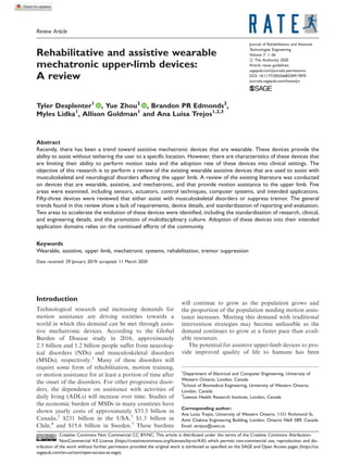
  • 6. information collected from the actuation system to provide system feedback was found in 36% of devices. It is also common to use sensors external to the wear- able device to collect data during the experimentation process. However, this does not contribute to the real- time control of the device. Within this section, the sens- ing system will refer to the actual sensor itself and the pre-processing required for the signal to be usable by the control system, this includes additional circuitry required for sensor functionality, filtering, amplifica- tion, and rectification of the signal. A visual depiction of how the sensing modalities of the reviewed devices are distributed is shown in Figure 1. Physiological sensing. Within wearable assistive devices, physiological signal-based sensing is often used to detect signals indicative of a user’s motion or force intention. For situations where the user desires to move but is unable to do so, such as nerve or muscular damage, sensing of physiological signals is crucial. From the 23 devices reviewed that incorporate physio- logical sensing: • 19 (82.6%) use EMG signals, which measure electri- cal activity of muscles, • 3 (13%) use electroencephalogram (EEG) signals, which measure electrical activity of the brain, • and 1 (0.4%) uses EMG and muscle–force stiffness signals, which measure the change in force of a muscle as it contracts.26 The physiological signals collected are often of a small amplitude, susceptible to noise, and can be chal- lenging to classify. Still, 43% of the devices reviewed have incorporated this type of sensor-based feedback. EMG. EMG is the measurement of the electrical potentials produced at the muscle.78 These myoelectric signals are a result of the person’s intention to move. In wearable applications, surface electromyography (sEMG) is the method typically used to obtain data. sEMG electrodes are placed onto the surface of the skin and electrically coupled to the action potential signals of the muscle, resulting in a voltage measure- ment of the muscle activity. All of the devices employing sEMG to collect muscle signals using gelled contact electrodes, abide by Surface ElectroMyoGraphy for the Non-Invasive Assessment of Muscles standards.79 This standard ensures electro- mechanical stability and reduces noise. The electrodes are placed in a bipolar configuration, such that two electrode sites are placed over each muscle of interest. The two channels undergo differential amplification to eliminate the common-mode signal, allowing the changes in muscle activity to be more evident. Use of hydrogel ensures that the electrode properly adheres to the arm, preventing sensor movement and motion artifacts. In each of the studies, sEMG signals were recorded from the muscles of interest, depending on the limb segment assisted by the device. In the nine studies where sEMG was used to control a hand orthosis,42,46,49,53,57,58,65,66,70,71,75,76 five report the muscles from which signals were collected. These were: flexor digitorum superficialis,65 flexor policus longus,65 flexor digitorum profundus,53,70,71,75,76 exten- sor digitorum communis,49,53,70,71,75,76 extensor digito- rum superficialis,49 abductor pollicis brevis, biceps brachii, and triceps brachii.70,71 The motion supported by these devices was the flexion–extension of the fingers and the thumb. Eleven systems use sEMG for control of the elbow joint.11,20,22–24,28,30,32,34,40 Nine of these systems were concerned only with the flexion–extension motion of the elbow and eight of these reported the muscles from which signals were obtained. In accordance with Figure 1. The distribution of sensing modalities across the reviewed devices. Electromyography (EMG), electroencephalography (EEG), and EMG and muscle–force (EMGþMF) sensing are subcategories of physiological sensing, while biokinematic and force sensing are subcategories of biomechanical sensing. In the case of biomechanical sensing, some devices used both biokinematic and force sensing. The size of the bubbles in this figure is scaled to show the relative difference between the number of devices that used each of the sensing modalities. 6 Journal of Rehabilitation and Assistive Technologies Engineering
  • 7. the arm’s physiology, every system placed electrodes over the biceps brachii and triceps brachii muscles. Additionally, two of the systems recorded from the brachioradialis and one recorded from each the anco- neus and flexor carpi ulnaris.20,32 Among the two systems that also supported the pro- nation–supination motion of the forearm, both recorded from the biceps brachii, triceps brachii, bra- chioradialis, and flexor carpi ulnaris.20,40 One of these devices looked at muscles from the extensor digitorum and palmaris longus, which are not typically associated with motion of the forearm or elbow.40 However, this device analyses the flexion–extension and ulnar–radial deviation of the wrist joint. Due to the erratic nature of the sEMG signal, it must undergo a relatively large amount of pre- processing compared to other signals before it can be used as input to a control system. Among the devices reviewed, 13 mention some pre-processing details.11,22– 24,28,32,34,40,49,53,57,58,65,70,71 Amplification noted in the reviewed studies was as follows: Tang et al. used an unspecified preamplifier,32 Stein et al. applied a gain of 300,11 Tong et al. applied a gain of 800,70 and Delph et al. used two gain stages, a 10 times gain stage followed by a selectable gain stage.53 The filters used ranged both in type and cutoff frequency, as described among 11 devices.11,22,23,28,32,34,40,49,53,65,70,71 Fourth-order high and low pass filters were a popular choice, used by four devices.28,32,34,53 Wang and Huang used a band pass filter with a range of 100–1000 Hz,34 Delph et al. chose a high pass filter with a cutoff fre- quency of 10 Hz and a low pass filter with a cutoff frequency of 750 Hz,53 and Kyrylova used a 10 Hz high pass filter.28 Ando et al. chose a third-order 18 dB/octave high pass filter and an eighth-order ellip- tic filter with a cutoff frequency of 550 Hz.22 Other filters used include Stein’s band pass filter with a range of 10 Hz–3.12 kHz,11 Tong’s 10–500 Hz band pass filter, Vaca Benitez’s et al. variance filter,23 Xiao and Menon’s use of fourth-order autoregression,40 and Mulas et al.’s moving average filter.65 Rectification of the EMG signal was reported by Tang et al.,32 and signal shifting circuits were used by Cao and Zhang and Delph et al. to shift the voltage recorded into the range supported by the analog-to- digital converters (ADCs).49,53 Tang, Vaca Benitez, Xiao, In et al., Desplenter et al., and Kyrylova all cal- culated the root mean square (RMS) of the filtered EMG data.23,24,28,32,40,57,58 The EMG sampling rate among the devices reviewed ranged from 250 Hz57,58 to 8 kHz.34 Furthermore, the sensor systems surround- ing EMG data collection for wearable assistive devices varied greatly. EEG. EEG is a measurement of the brain’s electrical potentials from the scalp.80 These signals were used to control three of the mechatronic systems reviewed. All three publications report using the wireless EPOCþ EEG headset (EMOTIV Inc., USA) to record signals across the frontal and temporal lobes.21,29,54 The system consists of 14 saline-based wet electrodes in 10–20 standard locations, and two reference electrodes in the noise cancellation P3/P4 location attached to a headset that wraps around the exterior of the cranium. Fok et al. state that the EPOC device design did not fully cover the motor cortex.54 The headset operates at a 0.2–43 Hz bandwidth with built-in 50 and 60 Hz dig- ital notch filters to avoid power line interference. A digital fifth-order Sinc filter was also used to prepare data for analysis using the proprietary Cognitiv Suite software (EMOTIV Inc.). In these studies, the EEG headset was used to control elbow flexion–extension, forearm pronation–supination,21,29 wrist flexion–exten- sion, radial–ulnar deviation,21 and finger flexion–exten- sion.54 These studies indicate that the system was able to provide clear and accurate sensor data capable of controlling wearable assistive devices to support the elbow, wrist, and hand. The use of EEG allows a user with limited mobility, or even with an amputation, with an accessible way to provide biofeedback during physical rehabilitation. However, the use of this system to determine motion intention presents challenges. The spatial resolution of the electrode with respect to the underlying neurons makes it difficult to determine the exact location of electrical activity. Therefore, significant amounts of crosstalk occur among electrodes while obtaining signal data, and only two simultaneous thoughts can be classified.21 Another pitfall is the efficacy of tracking intention. It is impossible for a researcher to evaluate the efficacy of the system when the user’s intention cannot be confirmed and may be considered hearsay.29 Xiao et al.21 and Looned et al.29 have reported the need for user training sessions to teach subjects how to con- trol the devices with their thoughts. In the future, EEG signals can be improved through the use of additional processing to eliminate artifacts, such as blinking. Work can be done to decouple the EEG signals from one another and from other biological signals recorded from the body, either through digital classification techniques or through hardware adjustments. Muscle–force measurement. Only one of the reviewed devices measured muscle–force stiffness as biofeedback. Kim et al. demonstrated the efficacy of this technique using piezoelectric resistive pressure sen- sors to control the flexion–extension movement of the elbow joint. The sensors within this device were attached to a band and positioned over the biceps Desplenter et al. 7
  • 8. brachii, triceps brachii, flexor carpi ulnaris, and bra- chioradialis, which are consistent with reported sEMG electrode locations for monitoring of this gross motion. The study reports that the use of muscle–force stiffness measurement was more accu- rately able to trigger a threshold-based actuation system than EMG, was less susceptible to noise and muscle fatigue, and did not require significant or uncomfortable preparation. The work did not detail the signal processing required or potential drawbacks of this sensing method. Still, extensive validation of muscle–force stiffness measurement does not yet exist.26 Biomechanical sensing. Biomechanical sensing refers to the outward mechanical motion that arises from human body processes, such as the measurement of the limb’s kinematic and dynamic properties. These methods of sensing are easier to integrate within the system than physiological sensing technologies, as they are often compact, self-contained, less sensitive to placement location, and less expensive. Accordingly, 55% of the devices incorporate biome- chanical sensing into their systems. Due to the reliance of biomechanical sensing on the user being able to pro- duce motion, limitations occur when the user suffers from paresis or is unable to produce the desired biome- chanical signal. Biokinematic sensing. Biokinematic sensing refers to the measurement and collection of kinematic data that arises from human motion. Biokinematic-based sensing was found within 86% of devices that use biomechan- ical sensing techniques. Information, such as joint angle, linear and rotational position, velocity, and acceleration, are used to provide biofeedback to devices using position-based closed-loop control systems. Many types of sensors can be incorporated under the position sensing umbrella. Seven of the devices opted to use potentiometers, which are capable of tracking rotational or linear motion along the joint or limb segment. Four devices measured data along the elbow,16,25,32,40 five tracked the wrist or hand,16,29,40,65,69 and one tracked the shoulder and forearm.16 Potentiometers are frequently used in mechatronic systems due to their low cost, lack of sus- ceptibility to electromagnetic interference, and ease of integration. No additional circuitry or power connec- tions are required to provide an absolute position read- ing within a particular range. Another sensing modality used for human-based kinematic measurements is the encoder, which was incorporated into six of the reviewed devi- ces.17,23,34,39,62,72–74 Encoders are used to determine elbow position in three devices,17,23,34 shoulder position by Brackbill et al.,17 hand position by Iqbal et al.62 and Xing et al.,72–74 and wrist position by Taheri.39 Some of the sensors used required a signal conditioning circuit and analog-to-digital conversion to provide absolute angular measurement. Furthermore, some were immune to degradation and environmental concerns, including vibration, temperature, and contamination. Xing et al. note the use of an unspecified filter and an ADC,72 while the other studies did not detail the remaining components of the sensing system. Various types of bend sensors, made from conduc- tive ink on a flexible laminate, were used by five devices to determine joint angles and deflection. The devices made by In et al. and Kang et al. used this modality to generate data related to the wrist.57,58,63 The remain- ing three systems use bend sensors on the finger joints.35,42,47 The full sensing system is described by Aubin et al., who reported that the output of bend sensors underwent voltage division, impedance buffer- ing, and amplification with an adjustable 1–10 gain, before the signals were digitized using a 10-bit ADC.47 Filtering and analog-to-digital conversion were not described in any of the other publications involving bending-based position sensors. The fabrica- tion of bend sensors is fairly robust, low cost, and experiences little hysteresis or noise. However, these sensors are susceptible to signal drift. Another popular kinematic-based sensor is the iner- tial measurement unit (IMU), which consists of one or more of the following components: accelerometers, gyroscopes, and magnetometers. These types of sensors may be combined in order to compensate for one another’s shortcomings. For instance, gyroscopes expe- rience significant drift, which can be compensated by using the accelerometer and magnetometer. Seven devices used some combination of the aforementioned components. Of these devices, four used gyro- scopes,19,25,29,41 five used accelerometers,16,19,28,37,41 one used magnetometers,41 and one used an unspecified IMU.18 Six of the systems collect elbow data,16,18,19,25,28,29 two collect shoulder data,16,18 one collects wrist data,41 and two measure hand data using IMUs.16,41 IMUs are generally inexpensive, com- pact and have a wide breadth of possible applications. However, more computational complexity is required than with other kinematic sensors to achieve informa- tion with efficacy. Within the devices reviewed, three mention filtering the sensor output.19,25,28 Both Herrnstadt and Menon, and Rocon et al. provide filter specifications used for the gyroscopes in their devices. They used a sixth-order elliptic high-pass filter with a 2 Hz cutoff25 and a high-pass filter with a cutoff of 0.3 Hz and a low-pass filter with a cutoff of 25 Hz,19 respectively. Meanwhile, Kyrylova reports fil- tering accelerometer signals with a second-order 8 Journal of Rehabilitation and Assistive Technologies Engineering
  • 9. Butterworth high-pass filter with a 2 Hz cutoff frequency.28 Force sensing. In addition to kinematic or position sensing, force-based sensing is also frequently used in wearable mechatronics for the upper limb. The rela- tionship between joint force and torque makes mea- surement of interaction forces between the limb and the device an attractive quantity to incorporate into a closed-loop controller. While many of the studies men- tion the use of force sensing, nine incorporate human driven forces into a closed-loop controller.23,42,51,52,55,59–62,64,69,72–74 Five of these sys- tems incorporate position-based biofeedback, as well.23,42,62,69,72–74 Of these nine devices, one tracks elbow data and the others track hand data. Vaca Benitez et al. track inter- action between the elbow and the device, using a min- iature inductive force sensor.23 The inductive force sensor is compact, lightweight, resistant to shock and vibration, short-circuit protected, and contains an amplification system. However, this sensor is more expensive than other force sensing technologies and only one can be used without experiencing interfer- ence.23 The force induced by the arm on the device is measured in order to calculate the amount of torque required to control the system. The other eight systems track forces exerted on the orthosis by the hand.42,51,52,55,59–62,64,69,72–74 All of these devices sense force through the change in resistive behavior due to mechanical deformations of the sensor. The two devices presented by Iqbal et al. used load cells attached to strain gauges, which are inexpensive and simple to manufacture but need protection from the environment. Strain gauges require strict signal condi- tioning and are often arranged as a Wheatstone bridge. Changes in resistance result in an imbalance and con- sequently a change in the voltage seen across the bridge.59–62 Typically, this representative voltage is then amplified and digitized within the sensor or elec- tronic system. Sandoval-Gonzalez opted for flex-force sensors connected to a force sensing circuit, which gen- erates a frequency based on an op-amp’s perceived capacitance and converts it to a representative voltage.69 Three of the remaining devices used force sensing resistors (FSRs).42,64,72–74 FSRs are all compact, flexi- ble, inexpensive, and experience low noise and long- term stability. However, they tend to have a poorer dynamic range and less accuracy than strain gauges. FSRs are also typically nonlinear and exhibit signifi- cant hysterisis.81 The signal conditioning required is voltage division and buffering, but these components of the sensing system were not described in the reviewed publications, aside from mention of amplification by Matheson and Brooker.64 This force- sensing modality requires calibration before use. Within seven of the hand-assistive devices that used force-based sensors, the sensors were placed beneath the mechanical structures of the device to determine the interaction force exerted between the finger and either the device or an external object. The eighth used silicon piezoresistive sensors to measure palmar interaction force.51,52 Actuator sensors. For some of the wearable assistive devices, measurements of non-biological quantities were used to provide feedback to the system. Eighteen of these devices collected information from the actuators to compare the performance against the expected behavior.17,19,27,28,30,31,34,37,39,40,51,52,59– 62,64,66,67,72–76 When discussing non-biological feedback, the type of sensing becomes dependent on principles of opera- tion of each actuator. Designs incorporating motors can rely on the same quantities as those measured from the human body, such as position, speed, and force within the actuated mechanisms. Ten of the devi- ces that used feedback from the actuator used kinematic-based sensing. Six of these report the use of encoders placed on the motors allowing them to determine the rotational position and speed at which it operates.17,28,34,51,52,59–62 Six other systems opted to track the linear position of the actuator.31,34,37,39,64,66 Three of these devices employed linear potentiometers attached to springs and Bowden cables to measure position.34,39,66 Kazi et al. and Matheson and Brooker used a linear variable voltage transducer (LVDT) for position sensing of piezoelectric and pneu- matic artificial muscle (PAM) actuators.37,64 Matheson and Brooker also reported amplification of the LVDT output.64 Ren et al. converted the current running through the motor into the speed of the motor through a model of the actuator.31 The behavior of pneumatic actuators can be evalu- ated better through the measurement of pressure, as they function through the conversion of compressed air energy into mechanical motion. Six of the reviewed devices used pressure sensing as feedback to the control system. Five of the instances attached the sensor direct- ly to a pneumatic actuator, with one reporting use of silicone pressure sensors at the diaphragm,67 one mea- suring pressure in the control valve,72–74 one unspeci- fied30 and two measuring the cylindrical chamber pressure of the actuator.39,75,76 The final device uses cable-tension sensors made from strain gauges. Other dynamic actuator-based measurements are used for feedback in three additional systems. Xing et al. used force sensors to measure PAM forces in the finger and thumb.72–74 This allows for increased Desplenter et al. 9
  • 10. information and control of the actuator behavior, by returning information from each joint. Like with bio- logical quantities, strain gauges can be integrated into the device. For instance, Rocon et al. used these sensors to measure forces perpendicular to the motor shaft.19 While this information was later converted into torque values, Xiao et al. directly measured the torque along the axis of rotation coincident to the wrist flexion– extension and ulnar–radial deviation movements. KleinJan measured resistance within shape memory alloy wire actuators as an input to the control system.27 All systems using non-pressure-based dynam- ic measurements, included in this review, focus on the hand or wrist. Of these 18 devices, 3 use the measured actuator data as the only control input.27,31,67 Conversely, 2 of the remaining devices use physiological quanti- ties30,75,76 and 10 use biomechanical properties as other inputs.17,19,28,37,39,51,52,59–62,64,72,73 There are three devices that use both physiological, biomechani- cal, and on-actuator sensors.34,40,66 The related sensing systems of the on-actuator sensors are not often described. As a result, information is limited with regards to filtering, amplification, rectification, data conversion, and other pre-processing techniques. Overall comments and future directions. Through the review of existing devices, it is clear that a myriad of sensing modalities and quantities are incorporated into wearable assistive devices. Data are collected from both biological processes, such as physiological signals or mechanical motion of the limb, from the actuator, or both. However, many devices do not use sensor signals to dictate the behavior of the control and actuation systems. Sensor-based feedback was not used by 13% of the reviewed devices and appears to rely on predetermined motion paths or open-loop control.36,43,48,50,56,68,77 This may limit the precision of these systems and make them less responsive to the immediate needs of the user. Multi-modal sensing seems prevalent within wear- able assistive devices, based on the devices reviewed. Through the use of multiple sensing modalities, a fuller profile of the user’s motion or intention can be provided. This allows accuracy and fatigue to be fur- ther characterized, and to track muscle health or range of motion over time. The sensors placed on the actua- tors provide insight into the functional output of the controller and the sensors measuring biological quan- tities are able to incorporate data related to the actual condition of the user. Realizing the potential benefits of multi-modal sensing, eight researchers have expressed the desire to incorporate additional sensing modalities into their future work.16,32,36,49,55,57,58,64,75,76 Three of those eight researchers specifically noted their interest in exploring the use of EMG signals in future work36,55,64 and two expressed the desire to add more EMG electrode sites.24,65 These researchers may be seeking more information to input to the controller. However, it is uncertain whether additional sensors will improve the system performance until they are implemented. Actuation The actuation system used for wearable assistive devi- ces is one of the vital components of the device as it provides the motion and torque/force to assist the user. An actuation system consists of the actuator and a method for transmitting the force to the required joints. The transmission method allows the actuator to be mounted remotely instead of attached directly to the joint and also change the direction of motion. For wearable devices, two main requirements related to the actuation are the force or torque required to com- plete the motion task and the range of motion of the joints involved in the motion task. Actuators are avail- able that can fulfill or exceed these requirements, but often fail to meet size and weight constraints that enable portability. Therefore, a major objective is to reduce the weight of the device, which is partially done through minimizing the size of the actuation system, while meeting the motion requirements. Based on the difficulty of meeting actuation require- ments, a wide variety of different actuation systems have been proposed in the reviewed devices. The types of actuators found in these devices are direct cur- rent (DC) motors, pneumatic actuators, hydraulic actuators, electromagnetic friction brakes, magneto- rheological fluid-based actuators, shape memory alloy actuators, twisted coiled actuators (TCAs), and piezo- electric actuators. The frequency of use of each of these actuation systems categorized by the targeted limb seg- ment is shown in Figure 2. DC motors are the most commonly used actuator (62% of devices), followed by pneumatic actuators (21% of devices). The remaining types of actuators are only used once or twice. The popularity of DC motors is likely due to being easier to implement than other actuators, while also being capable of providing the required actuation. However, DC motors are not a perfect or global solu- tion and this has led to implementing less commonly used actuators. Actuator designs for the hand focus on gripping force as a requirement instead of torque requirements for each of the hand and finger segments. In et al.58 suggest that a pinch force of 20 N and a wrap grasp force of 40 N would be sufficient to execute some ADLs. Of the devices that actuate the shoulder, elbow, and wrist joints, 41% listed the torque applied 10 Journal of Rehabilitation and Assistive Technologies Engineering
  • 11. to the joint.16,21,23–25,28–31,36,40 Figure 3 shows the aver- age torque and range of torques for each joint con- trasted to the torque values for healthy human joints performing ADLs. In device designs that list torque specifications, the joint torque of these devices are able to meet the torque demands for ADLs as gathered from the study performed by Rosen et al.82 DC motors. In this review, 62% of devices use a DC motor for actuation. Most notably, DC motors have been used to actuate each of the upper–limb segments in this review. The large selection of commercially available DC motors is what makes this type of actua- tor so popular. In general, implementation of these actuators is much easier compared to most other types of actuators. Of the devices employing DC motors, 42% used brushed DC motors,11,34,40,43,49– 54,59,60,62,63 24% used brushless DC motors,17,19,23,24,28,31,41,58 6% used both brush and brushless DC motors,21,29 and 28% do not specify the type of DC motor that is used. Rotational motion is provided by 82%11,17–19,21–24,28,29,31,33,34,40,43,47,49–53,58– 60,62,63,65,69 of these DC motors and the remaining 18% provide linear motion.36,46,54,55,66,70 The rotational DC motors all require a gearhead to increase the torque output, which is transmitted to the required joint through either cables, Bowden cables, gears, or link- ages. The linear motion DC motors are all connected to the actuated joint using linkages. For wearable assistive devices, brushless DC motors are generally a better choice over brushed DC motors. The brushed DC motors have well behaved speed– torque characteristics are adaptable, and are easy to control, which can make them a great option for Figure 2. Frequency of actuator type based on the targeted body segment. Figure 3. Average and range of torques of the reviewed devices compared to average torque values for activities of daily living (ADL) across different joints. The torque values of ADLs are taken from a study by Rosen et al.82 Desplenter et al. 11
  • 12. prototyping and sub-system evaluations.83 However, brushless DC motors have reduced maintenance, higher output power, better heat dissipation, and the ability to maintain or increase torque at different speeds.84 The downside to brushless DC motors is that they are more expensive than brushed DC motors and the control is more complex. Pneumatic actuators. Pneumatic actuators were the second most commonly used actuator in the reviewed devices. Compared to DC motors, pneumatic actuators offer a higher power-to-weight ratio, excluding the actuator infrastructure, and compliant actuation. Of the 12 devices using pneumatic actuators, nine used PAMs,16,20,26,32,35,42,48,64,72 2 used pneumatic bending actuators,75–77 and 1 used a pneumatic cylinder actuator.39 PAM actuators consist of an inflatable bladder inside a braided mesh that is clamped on both ends. When the bladder is inflated, it results in a contraction of the PAM due to the constraints of the structure. In the listed devices, these actuators are placed along the forearm or upper-arm, such that a pulling force is applied to actuate a joint. Some devices used PAMs to actuate the joint in one direction,16,42,48,72 while others use an antagonistic setup to actuate in opposing directions.20,26,32,35,64 The main advantages for PAMs in a wearable device is that they are generally lighter than other actuators and are mechanically compliant. In addition, PAMs do not require a fixed joint center, allowing more variation in the design of devices that employ them. The disadvantages to PAMs are that they have a slow and nonlinear dynamic response, which makes them challenging to control.10,85 Yap et al. and Yun et al. have used pneumatic bend- ing actuators to provide assistance for hand motion.75–77 In these two devices, the actuators are attached along the fingers using either Velcro with a glove or straps, respectively. When the actuator is inflated, it causes a bending force. This actuator only provides a bending force in one direction, which means that it can only assist with flexing the finger, but not extending it. The advantage of this type of actuator is that it is placed directly on the finger joints, so no additional parts are needed for transmission of forces. The pneumatic cylinder actuator incorporated by Taheri can generate a push or pull force that is used for tremor suppression.39 The ability to provide force in both directions is an advantage that this type of actuator has over the PAM and pneumatic bending actuators, which can only provide force in one direction. Hydraulic actuators. Hydraulic actuators operate similar- ly to pneumatic actuators, but use a liquid for power transmission, instead of compressed air. In this review, hydraulic actuators were implemented in two of the devices. Polygerinos et al. use a custom made flexible fluidic actuator for assistive hand rehabilitation,67 while Pylatiuk et al. developed a custom made hydrau- lic bending actuator for assistive elbow rehabilitation.30 The advantages of hydraulic actuators are higher power density and higher efficiency than pneumatic actuators. However, hydraulic actuators have the potential to leak liquid and require more infrastructure to function, such as a pump and reservoir. This creates challenges to find biocompatible fluids that meet func- tional requirements and infrastructure that will not restrict the portability of the system. Electromagnetic friction brake. The electromechanical fric- tion brake uses an electromagnetic force to apply a frictional force on the rotating disk, which will slow or stop motion. Herrnstadt and Menon use an electro- magnetic friction brake for a tremor suppression device.25 This device operates by switching between applying no torque and a resistive torque, whose values were not specified. The electromagnetic friction brake is only useful for applications where a motion produced by the user needs to be resisted, such as tremor suppression. A big limitation to these brakes is that the best performance occurs in a range that is near the maximum output torque. The output torque is generally unstable when it is not in this upper end of the torque range. Therefore, application of this actua- tor relies on the condition that the required suppression torque varies less than the stable range of output torque. Magnetorheological fluid actuators. Only one device in this review used a magnetorheological fluid actuator to provide tremor suppression of the wrist.38 Magnetorheological fluid actuators use a magnetic field to vary the viscosity of the magnetorheological fluid. By altering the viscosity of the fluid, the actuator can be used to slow or stop movement of a joint. As with electromagnetic friction brakes, this type of actu- ator can only be used to resist forces. As a result, mag- netorheological fluid actuators are best suited for suppression of undesired motion. The advantage of this type of actuator is that it has a fast response to control inputs. However, the large weight of these actuators limits the wearability of devices employing them and the actuators themselves have an impact on voluntary motion. Shape memory alloy actuators. Shape memory alloy actua- tors were implemented by two of the reviewed devi- ces.27,56 Both of these devices incorporated shape memory alloy cables to drive joint motion. Shape 12 Journal of Rehabilitation and Assistive Technologies Engineering
  • 13. memory alloy cables undergo a phase transformation from a flexible state (Martensite) to a rigid state (Austenite). They can be trained to remember a desired shape upon heating. The advantages of this type of actuator are that it has a silent actuation and a simple structure. However, shape memory alloy cables exhibit nonlinear characteristics, low energy effi- ciency, and a slow response to control inputs. The low energy efficiency is due to the cables being heated through Joule heating, while the slow response is caused by differing heating and cooling rates. Reducing cooling time of the cables would likely require increasing the weight and the cost of the device. Further research is required to improve these actuators and capitalize on their benefits. Twisted coiled actuators. TCAs are a more recent technol- ogy to be used in wearable assistive devices. Saharan et al. uses TCAs in a hand orthosis in order to assist finger motion.68 TCAs consist of a fiber that has been twisted and coiled, while under tension. When heat is applied to the fibers, TCAs can contract by up to 49% of their initial length.86 Additionally, the energy density has been recorded as high as 5.3 kW/kg,87 which is sig- nificantly higher than human muscle (200 W/kg).88 However, similar to the shape memory alloy cables, the downside to this type of actuator is the low energy efficiency, due to the inherent energy losses of a thermal actuator. Furthermore, TCAs require much higher temperatures, than human tissue can withstand, to function. For example, Saharan’s design used tem- peratures up to 250 C. Therefore, thermal protection is required in order to deploy this actuation technology in wearable applications. Piezoelectric bimorph actuators. Piezoelectric bimorph actuators were implemented in one of the wearable assistive devices. Kazi et al. use a piezoelectric bimorph actuator to suppress tremors occurring in the wrist joint.37 This actuator consists of two piezo plates bonded together with opposite polarity, such that one expands, while the other contracts, causing it to bend. Using piezoelectric bimorph actuators provides devel- opers with a fast response and low power actuation. However, the small range of motion produced by these actuators limits the opportunity for their applica- tion. Kazi’s device did not describe any specifications of the actuator, making it difficult to compare against other types of actuators. Actuator placement and transmission. The placement of actuators falls into one of the following three catego- ries: on the device joint, near the joint, and away from the joint. Some of the lighter actuators, such as the piezoelectric bimorph actuator and the hydraulic bending actuator, are capable of being directly attached to the joint.30,37 Being placed on the joint removes the need for additional transmission and helps achieve a lower overall system weight. Many of the reviewed devices place the actuator near the joint of interest. However, this design decision requires a trans- mission structure in order to actuate the joint. The transmission types for actuators placed near the joint include gears,19,22–25,28,31,69 cables,47,64,65,68,72 link- ages,54,70 or a combination of these transmission meth- ods.21,33,34,40,43,48–50,52,53,55,57,59,62,63 The downside to having actuators near the joint is the required transmis- sion will increase the size and weight of the device. Furthermore, transmission systems, typically, are not 100% efficient creating power losses between mecha- nisms. A few of the reviewed devices place the actuator away from the actuated joint, either on the back of or supported separately from the user. In this review, devices with actuators placed on the back use either cables with pulleys17,18 or Bowden cables11,53,66 for transmission of force, whereas the devices with the actuators placed away from the body use Bowden cables.47,49,63 The advantage of placing the actuators on the back is that it is easier to support the weight on the torso instead of the arm. Devices with the actua- tors away from the user are easier for the user to sup- port, but they can limit the mobility of the user. A breakdown of the actuator type, based on placement, is shown in Figure 4. Overall comments and future directions. Actuation systems are critical components of wearable assistive devices, for without them no physical assistance can be gener- ated. After examining the actuators, it is clear that the application plays an important role in actuator choice. DC motors and pneumatic actuators are the most common across the reviewed devices. However, seven other types of actuators have been proposed. The vari- ety of actuation systems suggests that no one type of actuator can provide a global solution for wearable assistive devices. Two of the main challenges with the reported devi- ces are the size and weight of the actuators, and the lack of actuator requirements and specifications. First, minimizing the size and weight of the devices can be partly achieved by reducing the size or weight of the actuation system. Two potential avenues for reducing these aspects include continuing to improve existing actuators and consider new ways to implement the actuators. Currently, most devices use DC motors due to their reliability and ease of implementation, but they are bulky and heavy. Other emerging types of actuators may reduce the size of devices, but are not as reliable or easy to control. As a result, both types of actuators can benefit from continued Desplenter et al. 13
  • 14. improvements. The other avenue is to develop new ways to implement the actuators. This includes finding ways to reduce the number of actuators used or posi- tioning the actuators such that the weight is less of a burden on the user. Second, most of the reviewed devi- ces do not provide all of the necessary information for developers to make an informed decision about their usage. Without that information, it can be difficult to evaluate the actuation and find ways to improve upon it. Ideally, researchers would provide the force or torque range, range of motion, speed, and weight of the actuation system, as well as actuation requirements for the intended application. This is especially impor- tant as it can increase the opportunities to study new actuation technologies. Control The control system of a wearable assistive device man- ages the behavior of the actuator using a control path- way with or without the help of sensory input. The input, output, feedback state, and strategy (internal model) are important aspects of these control systems and can be used to categorize them.89 It was found that control systems were developed to use physiological signals (such as EMG), biomechanical signals (such as joint position), or a combination of these two types of signals as inputs. Systems incorporated both closed-loop and open-loop feedback strategies to regu- late position, velocity, acceleration, force, or torque outputs. Finally, their internal models included propor- tional–integral–derivative (PID) control, threshold control, sliding-mode control, machine learning con- trol, biomechanical model control, empirical model control, and other control methods. In this section, the review of the control system of the wearable assistive devices is presented from the per- spective of their internal models. A generalized control system model is presented in Figure 5. Due to insuffi- cient information provided in some of the reviewed manuscripts, the control systems of 19% of the devices were unavailable to be included in this section. PID control. PID controllers and their variants have been the mainstay of the control system of wearable assistive devices. A PID-based controller operates based on the error between the measured signal and the desired signal, hence it does not require a complex mathematical realization of the plant. Its advantages in computational load, control accuracy, simplicity, and robustness have facilitated the development of wear- able assistive devices in recent years. Pylatiuk et al.,30 Mulas et al.,65 Desplenter et al.,24 Aubin et al.,47 and Cao and Zhang49 adopted closed- loop proportional control in their wearable exoskeleton devices. These control systems manage the speed of the actuation systems to be proportional to the measured EMG intensity. This strategy provides more controlla- bility to the user than the threshold control system. Although these devices do not estimate the user’s Figure 4. Frequency of devices and actuator types for each actuator location. 14 Journal of Rehabilitation and Assistive Technologies Engineering
  • 15. intended motion, the reduced complexity of these con- trollers makes them more suitable for implementation with lower-cost embedded computer systems. Brackbill et al.,17 Lessard et al.,18 Ren et al,31 Andrikopoulos et al.,35 Chiri et al.,52 and Wu et al.74 adopted closed-loop PID control in their wearable exo- skeleton devices. The control accuracy of these devices is reduced largely in the presence of low frequency dis- turbances, which is a non-negligible issue in wearable assistive devices. The jitters from the controller output may also reduce overall control accuracy by introduc- ing unwanted interactions from other inputs as distur- bances. Furthermore, these control strategies require improvement in adaptability for applications with dif- ferent users and scenarios, such as incorporating phys- iological signal-based control, or adaptive control. Lastly, Wu et al. developed a self-tuning fuzzy PID for a wearable rehabilitation device. The parameters of the PID controller can be tuned adaptively according to the error. Such control systems not only maintain the advantages of the conventional PID controller, but can achieve higher control performance and accuracy. Threshold control. Several of the articles reviewed imple- mented a type of control called threshold control. This category of control applies to EMG-based wearable exoskeleton devices, which required the determination of a percentage threshold with respect to the user’s maximum voluntary contraction. A typical maximum voluntary contraction test is required to calibrate the system. The devices are activated when the detected EMG signal exceeds the threshold and actuated at a predefined speed. Tong et al.,70,71 Yap et al.,76 and Delph et al.53 chose 20% to 30% of the maximum vol- untary contraction as the threshold. Xiao et al. developed a closed-loop threshold-con- trolled brain–computer interface (BCI) for stroke reha- bilitation.21 This system is designed to identify one conscious motion command at a time to activate the different movements of the device. For each conscious motion command, a sequential control scheme was pre- defined by the researchers. The commands consist of three stages, which are pre-decision, decision, and post- decision. A threshold was predefined for each stage to compare with the magnitude of the user’s EEG signal, in order to determine the intention of the user.21 If the average activation power is beyond the threshold, then the device is actuated. This control scheme was tested on one healthy volunteer. Although the results showed good performance when distinguishing between a con- scious thought and the neutral state, the fact that they have only tested on a single subject is a considerable limitation. More subjects are required to validate the proposed control system. In addition, this system requires a long time-window to distinguish a valid con- scious command, which is a drawback for real-time control, since it may cause undesired actuation of the user’s joint. Similarly, Fok et al. adopted the closed-loop thresh- old control in a wearable assistive device for stroke rehabilitation.54 Instead of using a sequential control scheme, this system developed a least mean square adaptive filter to match its gain to the change of the input signal. Although the accuracy still requires fur- ther improvement, the author claimed that the real- time performance and the accuracy of the system exceeded previous studies and that this device holds the possibility for in-home treatment. Sliding-mode control. Another type of control system is called the sliding-mode controller (SMC). Polygerinos et al. developed a rehabilitation glove using an SMC.67 This control system is constructed by one piecewise function that describes the general form of the device. Although such a controller does not require an explicit model of the system, it requires the system’s behavior to be continuous and smooth, which is not the general case in human–machine interactions. Furthermore, this control strategy requires the actuators to cope with high frequency control actions, which could affect the product life of the system for patient use. Machine learning control. The aforementioned control systems are undoubtedly simple control strategies to Figure 5. A generalized control system block diagram for wearable assistive devices. In this example, estimation controllers are typically developed as threshold, sliding-mode, machine learning, biomechanical model, or empirical model controllers, while actuation controllers are commonly PID-based controllers. The control system architecture and details of each block will vary based on the needs of the specific device or application. Desplenter et al. 15
  • 16. use for a wearable assistive device. However, this sim- plicity limits the ability for the user to control the device, since the controlled parameters, such as speed and force, are not adaptive. To improve the user con- trollability, artificial intelligence has been implemented to estimate the user’s voluntary motion.32,40 For exam- ple, Tang et al. adopted a closed-loop back-propaga- tion neural network to estimate the target joint angle.32 An EMG-to-angle model was built for pattern recog- nition in the back-propagation neural network, and the RMS of the EMG was used as the input to the classi- fier. The evaluation of the control scheme showed that the proposed system provides an effective way to esti- mate the user’s motion in real time, but the estimation error varies with different motions. Moreover, every subject has to go through a procedure to train the system to recognize their input signals. A more complex closed-loop neural network-based control system and a support vector machine-based control system were developed and compared by Xiao and Menon.40 To increase the accuracy of the classifiers, six features were calculated from the raw EMG data: the RMS value, four coefficients of a fourth-order auto-regression model, and the wave- length. The extraction of these features created a time delay of 0.124 s. The evaluation of the two classifiers showed that support vector machines had better per- formance than feed forward neural network, and could identify the levels and directions of the user’s wrist torque better. The authors mainly studied the applica- tion of artificial intelligence in estimating the torque of the user’s joint. However, it is not sufficient to apply such technique in an assistive device without motion estimation. To develop a fully functional assistive device, additional research on motion estimation is needed. In addition to the artificial neural network, a closed- loop linear classifier method was used to transform EEG signals to an appropriate control command.29 In the field of machine learning, a linear classifier iden- tifies an object’s characteristics by forming a classifica- tion decision using a linear combination of features. This technique works well for systems with multiple features (variables). Although accuracy is lower for linear classifiers compared to nonlinear classifiers, the computational speed of the former is much higher for training and testing. Looned et al. adopted this tech- nique to identify five motion patterns: elbow extension, elbow flexion, wrist pronation, wrist supination, and hand open.29 The system achieved an average classifi- cation accuracy of 98% from five volunteers during single task evaluation. One limitation of machine learning controllers is the amount of data that are required to train the models. In order to derive an optimized model, many subjects and data sets are needed. Tang et al. required 48 data sets to train their model for each of the 2-s, 4-s, and 8-s dura- tion elbow motions. Each data set consisted of four EMG channels and one elbow angle channel of data, which were sampled at 1024 Hz. As a result, the train- ing data consists of over 3.4 million data points that are needed to train the model. Even given this volume of training data, the neural networks still only achieved an average RMS error of 10:9 during control of their device. Neither Xiao et al. nor Looned et al. discussed how much data was used to train their models. This highlights the need for developers to both examine the accuracy–computational demand trade-off and provide these details within their research articles. Biomechanical model control. Although non-physiological model-based control systems have better system response performance compared to other control strat- egies, their control accuracy is limited. To improve the performance of wearable assistive devices, Iqbal et al.,59,60 and Taheri et al.90 incorporated the dynamic model of human joints into their control systems. Although the control accuracy of such devices largely depends on the complexity of the model, the potential of these control methods has been recognized by the research community, and may likely become one of the common options for the control system design of wear- able assistive devices. Since joint dynamics are the direct result of muscle activation and other biological phenomena together, such as joint friction, to control a wearable exoskeleton device, Ueda et al. investigated applying simplified muscle models together with a joint dynamic model using EMG input. This study proposed an individual muscle force control algorithm that aims to obtain a wider variety of muscle activity data.20 This algorithm estimates the amount and direction of the force of the subject’s hand by modeling nine joints from the torso to the wrist. Although the simulation and experimental validations have shown the validity of the proposed concept, future work is required to improve the control accuracy, to validate the efficacy, and to validate the system with dynamic tasks. Empirical model control. A robust mechatronic system often uses a feedback control strategy. However, this does not necessarily mean that control systems without sensory feedback are obsolete in wearable assistive devices. The open-loop empirical process control uses a predefined model to associate the input signal to the output signal with no feedback. The application of such control systems is often for the purpose of initial testing, monitoring, evaluation, or low-end control. Sugar et al.,16 Kazi et al.,37 Higuma et al.,36 Kang et al.,63 Yun et al.,77 Allotta et al.,43,44 and Conti et al.45 adopted open-loop empirical process control 16 Journal of Rehabilitation and Assistive Technologies Engineering
  • 17. in their studies. These are undoubtedly simple control strategies to use for a wearable assistive device. However, the lack of sensory feedback results in lower accuracy and reliability in general, compared to their closed-loop counterparts. Although such control methods are easy to implement and have a low relative cost, the increasing demand on smart technology forces research on wearable assistive devices to adopt smart feedback control strategies. Other control strategies. In addition to the aforemen- tioned control systems, Vaca Benitez et al. imple- mented a multi-input, single output model structure in a wearable elbow rehabilitation brace.23 This model is based on system identification with a recursive least square (RLS) algorithm, which utilizes EMG, position and force signals from the user. The proposed system showed good performance in matching the user’s real signals. However, the RLS algorithm reacted sensitively to the noise in the signals, especially the EMG signal. This is due to surface EMG signals con- taining a large portion of noise and muscle crosstalk. Although the proposed system presented promising results, it is crucial to improve the robustness of the algorithm to the noise residing in the sampled signals. Kyrylova proposed a simplified neural activation model that estimates the muscle activities from two antagonistic muscle groups.28 This model was integrat- ed in a Kalman filter to generate the control signal for a wearable assistive device using EMG and joint position signals. With the help of the Kalman filter, the differ- ence of neural activation from the two muscle groups can be mapped directly to the user’s motion history, which allows the speed profile to be estimated one step ahead. The experimental validation with pre- recorded data showed very promising results, in terms of the overall control accuracy of the system. To vali- date the efficacy of the device, on-patient assessment is required in the future. Thanks to the rapid growth of the computational capability of microcontrollers, the application of model-based control strategies in wearable assistive devices has increased considerably. Rocon et al. devel- oped a three degree-of-freedom wearable orthosis for tremor suppression using a model-based controller, called the weighted-frequency Fourier linear combiner (WFLC).19 Instead of modeling the musculoskeletal relations of the target joints and muscles, the WFLC adapts both the frequency and amplitude parameters of the Fourier series to the input signal. This method improved the response performance of the wearable assistive device, and the implementation of frequency estimation greatly improves the performance of the controller. However, the use of this pure sinusoidal model is insufficient to represent a real input signal. Overall comments and future directions. Control systems function as the decision maker of wearable assistive devices, and play an important role in processing the measured signal from the sensing system and in regu- lating the actuation system. Control strategies, such as threshold control, PID control, linear classifiers, among others, are commonly implemented in wearable assistive devices. These control strategies do not require the embedded system to have high computational power, leaving the embedded system with enough proc- essing time to perform other important tasks. This is an advantage that is especially important for devices that use physiological signals, such as EMG signals, since they often require multiple channels of data that are sampled at higher frequencies than those of voluntary motion. Since data sampling and processing occupy a large portion of the computational resources, the con- trol accuracy of such devices may be limited. The use of artificial intelligence-based and model- based control methods may result in better control accuracy than simpler control systems based on thresh- old or PID control, especially the ones that use physiological-based signals. To address the issue of high computational load of using these more advanced control systems, cloud computing could be a potential online solution, which is limited by the data transfer rates of the network. With the ultimate goal being real- time control of the device, the computational demands of the control system and limited computational resources available to these devices pose a major challenge. Computation Modern digital computer systems are the foundation for implementing a variety of aspects of sensing, actu- ation, and control of wearable assistive mechatronic devices. The complexity of these devices creates a large demand for processing, analysis, and storage of information, which is being supplied by computer sys- tems and electronic components. Although, the computer systems facilitate the interaction of all of the mechatronic system components, some authors have neglected to include important details relating to the computer systems used in the design, development, and testing of their devices. From the review, no description of the computer architectures or systems was given for 21% of the devices.20,27,33,37,38,42,48,50,55,62,64 Of the devices that provided computer system information, the general computer hardware and software specifications have been extracted, as follows. Computer hardware. Computer system hardware is described in 79% of the reviewed devices, although Desplenter et al. 17
  • 18. very briefly by some. The descriptions range from as vague as “a standard data acquisition board” to listing hardware components, their connections, and their communication protocols. General purpose computer systems, such as a laptop or personal computer, were listed as an integral component of the computer archi- tecture in 32% of the devices,16,17,21,24– 26,28,29,34,35,40,41,52,54,59,60,65,66,68,72,73 while 34% of devi- ces listed the use of off-the-shelf microcontroller boards.11,36,41–43,47,49,53,56,63,65–67,70,72,76,77 Where model numbers are listed, basic processor information can be looked up, but only 11% of the devices listed basic processor and memory information.18,22,28,29,35,65 To complement these computer systems, 26% of the devices are using other off-the-shelf electronics, such as data acquisition boards and sensing platforms.17,19,24,26,28,34,35,39,40,52,57,59–61,68,72–74 In order to increase the portability of these devices, the computer systems must be embedded within the devices or stored on the user’s body. This means that computer hardware analysis is important to ensure that the com- putational requirements can be factored in when designing these devices. A breakdown of the type of computer hardware systems is presented in Figure 6. Computer software. In terms of computer system soft- ware, a similar trend can be seen towards researchers using off-the-shelf software systems. The review reveals that 51% of the studies reported the use of off-the-shelf software with MATLAB (25% of the devices),16,19,23,26–28,32,41,46,48,52,55,65 including the Simulink tool kit,26,63,65 and LabVIEW (15% of the devices)21,25,26,35,40,51,54,57 being the most popular. Other software systems mentioned were OpenSim,18 SolidWorks,16,24,28,74,75 SimMechanics,16,43–45 ControlDesk,17 Emotiv Cognitiv Suite,21 OpenSignals,24,28 Presentation,23 Datalog,22 DAFUL,36,46 FEMAP,36 MPLAB,65 BCI2000 Framework,29,54 and XVR.69 Although authors are listing their software sys- tems, only 8% of the devices describe the operating system in which these software systems are execut- ed.22,28,35,41 The type of operating system that is used can have major effects on the execution of the control software and, therefore, should be reported. Programming languages, namely C and Cþþ, were used in 9% of the devices as a primary development tool for software.11,19,24,28,65 Very few descriptions of information regarding the software structure, complex- ity or timing can be found in the literature. Some of the software structure can be inferred from the control system descriptions, but it may not be possible to derive the entire software architecture from the control architecture, as they may not be mapped one-to-one. Overall comments and future directions. One of the suc- cesses seen with the computer systems is in the required power supplies. Both lithium-ion63,66 and lithium-poly- mer18,67,77 batteries have been used to power the motors and the electronics of these devices, making it possible to increase portability. These power supplies remove one of the aspects that tether these devices to specific locations. However, much work still remains in reducing power consumption of the electronics, as well as decreasing the weight of the battery, while extending the amount of power provided. Power supplies are an important research area that supports the vision of these devices being used in a continuous all-day manner. It is seen that many of the devices used desktop or laptop computer systems, off-the-shelf microcontrollers and other self-contained electronic systems for sensing or actuation, supporting the idea that developers are focusing on proof-of-concept development. This devel- opment strategy reduces the amount of time and resources needed to create a functioning prototype. By using off-the-shelf software systems, mechatronics engineers are able to prototype devices more rapidly. The popularity of the Simulink tool for MATLAB and LabVIEW leans toward the view that engineers in this field may be more comfortable using visual-based control system development tools. It may also reflect the fact that many of these devices are still prototypes and, therefore, developers are choosing development tools that they find more effective for rapid prototype development. One potential limitation of using these tools is that the control software developed with them is often not able to be used in the final product. Existing embedded computer systems are likely to be unable to meet the processing requirements using soft- ware systems developed for desktop computer systems. These software systems will not typically operate on these embedded systems. In cases where it is possible Figure 6. Distribution of computer hardware systems of wearable assistive devices. General computer systems include laptops, desktops and other personal computers, while the specialty/custom computer systems include microcontrollers, custom circuits, specialty computer systems, sensing electronics, and data acquisition boards. 18 Journal of Rehabilitation and Assistive Technologies Engineering
  • 19. to execute them on embedded systems, the embedded systems do not have enough resources to complete the tasks required of wearable assistive devices in similar time periods as their desktop counterparts. As a result, the development periods and costs will be increased to account for the redevelopment of the control software in way that enables them to be executed appropriately on embedded computer systems. This limitation could be mitigated by using software development methods and tools that are appropriate for the final product from the beginning of their development projects. Reconfigurable computer hardware, such as field- programmable gate arrays, may also be a potential solution, but have yet to be implemented and reported by this research community. Improvements to this research area can be made by development teams weighing in on what they consider important aspects of the software and hardware com- ponents that are required to replicate or evaluate results. The vagueness and lack of computer hardware and software details make it difficult to understand and reproduce the designs and experiments with wearable assistive devices. Even basic details of the computer systems, such as software versions, libraries, operating system software, model numbers of physical compo- nents, and processing resources, would help to mitigate this issue. One of the most important aspects for researchers and developers alike is to standardize infor- mation about the computer systems of these devices. If researchers are unable or unwilling to provide basic computational information, it hinders the evolution of this field. Many of the computer systems included in this review operate the device as expected because the computational environment has more resources than required. However, a limitation arises as the com- plexity of the computation grows, while the require- ments for power and space on the devices or body limit the resources available in such embedded comput- er systems. Applications In this review, the applications of these wearable assis- tive devices are aimed at assistance with human motion. Categorization was made in terms of targeted body segment, purpose, and functionality. The targeted body segments were defined here as those to which assistance was actively applied, as opposed to passive assistance or support. The purpose of each device refers to the specific motivation behind the research and design, which is directed towards a musculoskeletal dis- ease or clinical disorder that causes a known impair- ment. Functionality refers to the type of stimulus that the device is meant to provide to the wearer, such as assistive or resistive forces to the target joints, or suppressive forces for involuntary motion. The review of these characteristics reveals trends about the appli- cation of these devices. The targeted body segments were found to be divid- ed into four main upper body sections: hand/fingers, wrist, elbow, and shoulder. Of the reviewed devices, 87% targeted a single body segment, such as one or more fingers, the wrist, and the elbow, while 13% were developed for multiple body segments. All multi-segment wearable assistive devices were devel- oped such that the multiple targeted segments are directly connected in series. In total, three devices tar- geted the elbow and wrist,19–21 two devices targeted the elbow and shoulder,17,18 one device targeted the wrist and hand,41 and one device was developed for the shoulder, elbow, and wrist.16 Figure 7 gives a visual representation of the attention given to each joint by developers of the single-segment devices. In terms of the purpose driving the design of these devices, there was no specific clinical disease forcing the constraints or requirements for each design. Instead, the overlying objective for these devices was the resto- ration of ADLs in impaired individuals. Nevertheless, clinical diseases and disorders were referenced in many of the introductory statements as a motivational expla- nation, the most common being stroke, which was ref- erenced in 48% of the reviewed articles. Stroke was cited in most articles due to its prevalence. For instance, Burton et al. cited stroke as, “the single most common cause of severe disabilities in the devel- oped world”.48 The specified functionality of each device was found to be divided into musculoskeletal rehabilitation and tremor suppression. A review of rehabilitation modal- ities by Basteris et al. defined a rehabilitation device as one which can provide motion intention recognition and provide active assistive or resistive modalities depending on the patient’s progress.91 Since tremor is a ND that causes involuntary cyclic motion, the devices that are designed for this purpose require a different control architecture and performance constraints than Figure 7. Distribution of devices with respect to the targeted body segment. Desplenter et al. 19
  • 20. rehabilitative devices. From the literature, 87% of devi- ces were designed to rehabilitate MSDs, while 13% were designed to suppress involuntary tremor motion caused by NDs. Figure 8 shows the normalized distri- bution of rehabilitative and tremor suppressive devices for each body segment. Overall comments and future directions. The results from the analysis of applications, as seen in Figures 7 and 8, indicate a strong trend toward rehabilitation devices in the finger and elbow joints. One reason for this result could be due to limitations in the capabilities of existing actuation technology. For example, to assist the shoul- der joint during rehabilitation procedures, a larger actuator is required to produce motion of the arm. Not only would a large motor be heavier and larger, but the power consumption of the actuator would require larger power supplies to be carried by the person wearing the device. This is complicated further by the fact that the shoulder is a more complex joint and would require control of multiple degrees-of- freedom. Timmermans et al. concluded that recovery would be drastically improved if focus were equally placed on distal and proximal joints since ADLs require full mobility from every active joint.92 Currently, there is no wearable assistive device that provides active assistance to the entire arm. Therefore, further research should continue the trend towards development of multi-segment devices that provide assistance from the shoulder down to the fingers. Due to the complexity of humans and their motion, it is difficult to define requirements for a particular disease across all people. This lack of requirement makes it very challenging to design useful wearable assistive devices. Many devices examined in this review are still far from being ready for applications involving clinical testing. Discussion Developing mechatronic devices to assist with human motion has been an area of research interest for deca- des. However, improvements in technology have enabled an explosion in the development of assistive devices as wearable entities. In this review, 53 wearable assistive devices were examined to determine the state- of-the-art of the research and technologies driving their development. Five main areas, sensing, actuation, con- trol, computation, and applications, were explored to identify trends and challenges surrounding the develop- ment of these devices. The following discussion will present the general trends in the field of wearable assis- tive devices, challenges facing each of the five key areas, and potential solutions to improve these research domains. General trends A major societal problem is supporting the research demand for wearable assistive devices. The number of disorders far out-weighs the resources available to assist with treating them or increasing the quality of life of individuals suffering from these disorders. When looking across the reviewed devices, 57% were developed and presented within the last five years. This shows that research efforts have more than doubled in this time period, despite a lack of clear requirements from clinicians. The growth of wearable assistive devices is promis- ing and creates a positive outlook for these devices as solutions to the growing MSD and ND problems. However, due to the newness of these devices, this area of research is still quite immature. Currently, only one commercially available upper-limb wearable assistive device, the MyoPro, is available for clinical use. Commercialization may be difficult as clinicians are hesitant to use tools that are not regulated, while government agencies are hesitant to regulate tools that are not used, proven to be safe, or more effective than traditional interventions. Furthermore, it is difficult to objectively measure functional improvements in human motion, which are major criteria desired by both clini- cians and device regulators. Wearable assistive devices offer new opportunities to provide objective measure- ments of motion parameters, but the research connect- ing these measurements to patient outcomes is still limited. Of the devices presented in the literature, a large amount of variation is seen among the technologies and methods used to support these devices. Exploration of technologies is expected with any emerging research area, but, in this case, it is likely due to the inability of technologies to fully meet the Figure 8. The normalized distribution of devices by targeted body segment and functionality. The main applications for these devices are to either suppress tremor or to assist with muscu- loskeletal disorders (MSDs). 20 Journal of Rehabilitation and Assistive Technologies Engineering
  • 21. engineering requirements. The novelty of these devices is also seen from the lack of comparative studies in the literature. The complexity of these devices and variabil- ity of humans makes comparison a difficult task. Adding the fact that none of the devices are available commercially, the challenge of duplicating experimen- tal results and performing comparative studies is fur- ther increased. One of the biggest challenges facing the field of wearable assistive devices is the lack of requirements, details, and standards in the literature. Many of the reviewed articles provide potential lists of disorders, or propose their device for general motion assistance. This shows that there is a lack of clear requirements being given to developers from medical professionals regarding assistance with any particular disorder. In this review, the inclusion criteria used was not overly strict, as it stated only that the researchers had to vaguely describe at least three of the four areas of sens- ing, actuation, control, and computation. As a result, many devices were not included in the review as the descriptions could not meet these criteria. Of the devi- ces that were included, many of them had vague descriptions of these key areas, supporting a general lack of information crucial to the research community. The ability to understand, duplicate, compare, and improve upon existing research depends highly on the availability of this information and, therefore, is a hin- drance on the evolution of this field. Device evaluation and safety features were not dis- cussed in general. In some cases, evaluation of engi- neering criteria is performed on sub-systems, but no integration or system-level testing was performed and presented. In other cases, system testing occurs, but only on a limited number of participants. Either case makes it difficult to generalize the performance of the system. Although safety features are typically seen as later-stage requirements, discussion of the potential features would assist in creating a positive image of these devices. These scenarios might be expected of devices that are still in the prototyping and early devel- opment stages. However, performance testing and safety features are vital for them to become regulated medical devices. The ability to persuade the community to adopt these devices relies heavily on the performance of the device to behave as intended and for their safety systems to ensure no further harm is done to the end- user as a result of their usage. Sub-system challenges Sensing systems, functioning as the feedback link of a wearable assistive device, play an important role in proper control system execution and user monitoring. Based on the review of the existing sensing systems, a number of common limitations were identified, which include a lack of sensor feedback, insufficient sensing modalities, and a lack of proper calibration procedures. A wearable assistive device with open-loop control does not require the use of sensors. However, the system performance of such a configuration is often complemented by the use of fixed-step actuators. Although the complexity of such configurations is min- imized, the overall system accuracy is lower than sys- tems with closed-loop control. The human upper limb is a complex nonlinear system, which creates the design requirement for wear- able assistive devices to involve multiple sensing modal- ities in order to achieve high control accuracy. However, only 40% of systems used multiple sensing modalities. One reason could be that increasing the number of sensing modalities increases the computa- tional demand, cost, and system complexity. Although the performance of a system with a single sensing modality can be complemented by better con- trol strategies, such limitations still require greater con- sideration from researchers for the future development of a wearable assistive device. Lastly, sensor calibration is often the first step for validating devices on humans. Due to individual differ- ences, the sensing system should be calibrated individ- ually to achieve optimal performance. For a device with many sensors, calibration of the sensors may be costly. However, the potential impact of not calibrating the system includes compromised system performance, system failure, and even risks for the user’s safety. As a result, maximizing adoption of the device must consid- er the trade-off between the cost and the performance related to calibration. In this review, the majority of the systems did not detail the sensor calibration process. Including this information in the dissemination of future studies will help to increase device adoption through an analysis of the trade-off between factors related to sensing systems and calibration. Actuation systems are important to enable the inter- action between the wearable assistive device and the human. Through the analysis of the literature, it was found that DC motors and pneumatic actuators are the most commonly used actuators. However, these actua- tion technologies are not meeting the needs of wearable assistive devices, as the size, weight, and power con- sumption of the actuators limit the application of the devices. As a result, there are new types of actuators being tested and developed. In addition, some actuators used in the existing devi- ces were not justified as to their usage over alternative actuators. Information, such as mechanical design, user interface, or safety considerations, which play a crucial role in actuation selection, were not always included. The lack of these considerations could result in a Desplenter et al. 21