Pseudo-Sections for Target Depth Estimations Using Physical Modelling Studies in Resistivity Prospecting

Once the data are acquired either in the Lab or in the field for investigation of the natural resources, the data are presented in the form of profiles in the case of resistivity/Induced Polarization (IP) profiling or in the form of curves for comparison with the available Master curves. It is, however, possible to plot both sounding and profiling data obtained over a traverse on a single depth section where the depth to the top of the target is indicated, which is called pseudo-section.. It is named so to emphasize the fact that these are only apparent values in terms of magnitude and location. These pseudo-sections are carefully interpreted by different methods such as inversion techniques to get the true resistivity and IP effect. All that one has to do is to prepare the modified pseudo-sections with two or more arrays possible corroboration along a traverse, in the middle of anomalous zone. If the positions of the maximum anomaly contour in the pseudo-sections with the arrays, by and large, agree with each other than one can recommend a borehole passing through such positions to strike the top of the target.

Recommended
More Related Content
What's hot
What's hot (20)
Similar to Pseudo-Sections for Target Depth Estimations Using Physical Modelling Studies in Resistivity Prospecting
Similar to Pseudo-Sections for Target Depth Estimations Using Physical Modelling Studies in Resistivity Prospecting (20)
More from Editor IJCATR
More from Editor IJCATR (20)
Recently uploaded
Recently uploaded (20)
Pseudo-Sections for Target Depth Estimations Using Physical Modelling Studies in Resistivity Prospecting
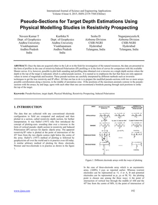
- 1. International Journal of Science and Engineering Applications Volume 4 Issue 4, 2015, ISSN-2319-7560 (Online) www.ijsea.com 192 Pseudo-Sections for Target Depth Estimations Using Physical Modelling Studies in Resistivity Prospecting Naveen Kumar T Dept. of Geophysics Andhra University Visakhapatnam Andhra Pradesh India Karthika N Dept. of Geophysics Andhra University Visakhapatnam Andhra Pradesh India Seshu D Airborne Division CSIR-NGRI Hyderabad Telangana, India Naganjaneyeulu K Airborne Division CSIR-NGRI Hyderabad Telangana, India ABSTRACT: Once the data are acquired either in the Lab or in the field for investigation of the natural resources, the data are presented in the form of profiles in the case of resistivity/Induced Polarization (IP) profiling or in the form of curves for comparison with the available Master curves. It is, however, possible to plot both sounding and profiling data obtained over a traverse on a single depth section where the depth to the top of the target is indicated, which is called pseudo-section.. It is named so to emphasize the fact that these are only apparent values in terms of magnitude and location. These pseudo-sections are carefully interpreted by different methods such as inversion techniques to get the true resistivity and IP effect. All that one has to do is to prepare the modified pseudo-sections with two or more arrays possible corroboration along a traverse, in the middle of anomalous zone. If the positions of the maximum anomaly contour in the pseudo- sections with the arrays, by and large, agree with each other than one can recommend a borehole passing through such positions to strike the top of the target. Keywords: Pseudo-Sections, target depth, Physical Modeling, Resistivity Prospecting, Induced Polarization __________________________________________________________________________________________ 1. INTRODUCTION The data that are collected with any conventional electrode configuration in field are computed and analysed and then plotted in a section, called resistivity depth section, for further interpretation. It was Hallof (1957) who first introduced the concept of plotting-cum- sounding data over a traverse in the form of vertical pseudo- depth section in resistivity and Induced Polarization (IP) surveys for dipole- dipole array. The apparent resistivity/IP value is plotted at the point of intersection of the 45o lines from the two dipole centres right below the centre of the array. Hallof’s (1957) method of plotting is followed by geophysicists all over the world and is in practice even till today. A similar arbitrary method of plotting for three- electrode, Wenner and two-electrode is in practice as shown in the figure 1. Figure.1. Different electrode arrays with the ways of plotting In the case of three-electrode array which is an asymmetric array, (AMN), I p1p2 as reported earlier. Whereas (current electrodes can be represented as +I, -I or A, B and potential electrodes can be represented as p1, p2 or M, N) the plotting point is chosen one among the three ways: i) the point of intersection of vertical line through the middle of AM and the 450 line from the centre of MN, ii) the point of intersection of
- 2. International Journal of Science and Engineering Applications Volume 4 Issue 4, 2015, ISSN-2319-7560 (Online) www.ijsea.com 193 the two 450 lines drawn through A and the middle of MN and iii) the point of intersection of the 450 line from A and the vertical line through the middle of MN. In case of Wenner array, the plotting point is chosen at depth equal to the intra-electrode spacing (a), right below the centre of the array. In two-electrode (AM) the plotting point is depth equal to the spacing AM below its centre. 2. MATERIALS AND METHODOLOGY Taking into account the Depth Investigation Characteristic (DIC) of Roy and Apparao (1971a, b), Edwards (1977) suggested an empirical approach for a modified pseudo section by plotting apparent resistivity / IP value at depth below an electrode array, equal to effective depth of investigation, computed for homogeneous ground for the electrode geometry. The effective depth of investigation for an array has been defined by Edwards (1977), as that depth at which 50% of the total contribution (signal) originates from above the depth and 50% from below based on the above theory. Table 1 shows DIC for different electrode arrays. Table 1: Depth Investigation Characteristics Array Median Depth of Investigation, Zmed/L Maximum Contribution Depth of Investigation, Zmax/L Dipole-Dipole N=0.5 0.101 0.066 1.0 0.139 0.101 2.0 0.174 0.130 3.0 0.192 0.147 4.0 0.203 0.155 5.0 0.211 0.162 6.0 0.216 0.167 7.0 0.220 0.170 8.0 0.224 0.173 Wenner 0.173 0.111 Three-Electrode 0.259 0.165 Two-Electrode (Infinity Electrode At 10L) 0.724 0.350 Edwards (1977) found that the theory has practical validity and physical application. And, Edwards (1977) further agreed in line with Roy and Apparao (1971a, b) that the DIC for homogeneous earth can be usefully applied for all practical purposes. Edwards (1977) showed for instance, a common rule of thumb for non- out cropping bodies: If the maximum IP effect occurs for n=3 or 4 in dipole array, the depth to the anomalous body is of the order of one dipole length ‘a’; if for n=1 or 2, the depth is less than or equal to ‘0.5a’; if n=5 or 6 the depth is greater than ‘a’. This rule is not inconsistent with the computed results of Roy and Apparao as shown in table.1 for homogeneous ground. This observation has, in fact, stimulated Edwards (1977) to carry out his work on modified pseudo- sections. Edwards (1977), however, claimed that, by his method of plotting, the pseudo-section facilities an approximate location for the top surface of the anomalous body, if the data covers a significant range of depths. This may allow one to infer the true geological disposition of the ground structure. Model and field studies carried out by Apparao and Sarma (1981, 1983) and Sarma et al (1993) so far, support, by and large, that the pseudo- sections (IP and/or resistivity) for any array based on depth of investigation as defined by Roy and Apparao (1971a, b) carry, however, a superior advantage, over the modified pseudo-depth section of Edwards (1977) in direct location of target which is the primary objective in mineral exploration. 3. CONSTRUCTION OF PSEUDO-DEPTH SECTIONS Depth levels are designed as per the depths of investigations defined by the electrode array and its size. The data acquired in the field/Lab are plotted on the same depth level taking into account the lateral and depth wise scales. When the array size is increased, the depth of investigation is also increases and the data acquired with the increasing space of the array is plotted on the new deeper depth level and this process is continued as long as the array size is increased. After the entire data set is marked on all depth levels, contours are drawn joining equipotential values which finally results into a pseudo-depth section. The pseudo-depth section facilitates an approximate location of the top surface of the anomalous body, if the data covers a significant range of depths. This may allow one to infer the geological disposition of the ground structure. This method can be applied right in the field spot after computation process is over. These pseudo sections play a significant role to study the nature of the sub-surface. Especially, when scanning the sub- surface using multi-electrode systems, the output is in the form of images which is nothing but a pseudo depth section. All the Electrical Resistivity Tomography (ERT) studies are presented in the form of pseudo sections. The final outcome of all the interpreted results in the case of 1D, 2D and 3D studies is nothing but a pseudo depth section. It apparently plays an important role in helping to understand shallow sub-surface geological architecture. 4. EXPERIMENTATION For carrying out the model experiments for construction of modified pseudo-depth sections over 1D, 2D and 3D conducting targets, the tank model is used. The cross-section of the tank is illustrated in the figure 2. Aluminium sheet (100 X 10 X 1), Horizontal Aluminium Cylinder (Radius=1.5cm)) and Aluminium Cylinder (Radius=3.0 cm) are used for the present study. The thickness of the conducting sheet is taken as one unit and all other parameters are expressed in terms of thickness only. In the case of Cylinder and Sphere, the radius is taken as one unit and all other parameters are expressed in terms of a radius only. Very interesting results are obtained which are discussed as follows. Figure 3 illustrates the pseudo-depth sections constructed over a conducting sheet of one unit
- 3. International Journal of Science and Engineering Applications Volume 4 Issue 4, 2015, ISSN-2319-7560 (Online) www.ijsea.com 194 thickness. The orientations of the sheet are horizontal (00 ), inclined (300 ), inclined (600 ) and Vertical (900 ) and the electrode configuration is Wenner. The depth of the sheet is taken as one unit i.e. 1.0 cm. Figure.2. Cross section of the tank Figure.3. Modified Pseudo-depth sections over conducting target at different orientations with Wenner array. Target depth: 1.0 cm Inclinations: 00, 300, 600, and 900 Figure.4. Pseudo- depth sections over conducting cylindrical target (R = 1.5 cm) with different electrode configurations. Target depth= 0.5 R for Two-electrode, Three-electrode, Wenner and d= 0.75 for Dipole-Dipole. Figure 4 depicts the modified pseudo depth sections over an infinitely conducting cylinder (R=1.5 cm) with different arrays viz., two-electrode, three-electrode, Wenner and dipole- dipole, submerged in the host medium, water contained in a model tank. Figure 5 illustrates the modified pseudo-depth sections over a conducting spherical target (R=3.0 cm) with different electrode configurations. The model experiments are carried out over the conducting sheet in different orientations only with Wenner array to study the nature of anomaly pattern with inclination of the target. In the case of conducting Cylindrical and Spherical targets, the experimentation is carried out with different arrays to understand the anomaly variation with the array and its size. Extreme care has been taken to fix the 2D and 3D targets in the model tank so that the signatures are recorded with the measuring sensor. The apparent resistivity of the host medium, water is also measured separately and it is tallied with the physical real value. All the measurements over the targets are free from any anticipated tank wall effects. For this purpose, measurements are carried out in the tank with no target in the tank. The anomaly falls right on top of the cross- section of the cylinder and spherical models. Fortunately, in mineral exploration, the targets are either highly resistive or highly conductive, precisely the situation where in modified pseudo sections enable a field geophysicist locate the targets at depth.
- 4. International Journal of Science and Engineering Applications Volume 4 Issue 4, 2015, ISSN-2319-7560 (Online) www.ijsea.com 195 Figure.5. Pseudo depth sections over conducting sphere (R=3.0 cm) with different electrode arrays. Depth of target (d = 0.333R). 5. RESULTS AND DISCUSSION Model tank resistivity pseudo- depth sections obtained over a metallic sheet (110 cm X 10 cm X 1 cm) submerged in host medium, water, with Wenner array are analyzed and studied. The orientations of the metallic sheet are horizontal (00 ), inclined (300 ), inclined (600 ) and vertical (900 ) and the electrode configuration is Wenner and the depth to the top of the target is 1.0 X t where’t’ is the thickness of the target which is taken as one unit. Further, the pseudo-depth sections over 2D (Horizontal Aluminum Cylinder) and 3D (Aluminum Spherical Target) conducting targets, with the arrays viz., two- electrode, three-electrode Wenner, Dipole-Dipole radius (R) of the cylinder or sphere is taken as one unit. The depth section is obtained as per the definition given by Roy and Apparao (1971a, b). It can be seen that for any electrode array the maximum anomaly contours close-up and fall right over the metallic target cross section while in depth sections prepared as per practice in vogue, the target position is much above the position of the maximum anomaly contour. The pseudo- depth section plotted and prepared as per maximum contribution concept indicates useful information to determine the depth of anomaly-causing target body in field investigations and for determining probably the approximate shape and size of the target. In other words the depth section may help us in finding out the anomaly- causing target. The surprisingly good results have led us to compare our pseudo- sections with those of Edwards (1977) for each of the arrays, using the same model data. An examination of the model pseudo-section shows that the maximum anomaly contour does not coincide with the target position and falls well below the target for any array, even though the pseudo-sections are much better- off than their corresponding pseudo sections plotted as per normal practice. A comparison is also made with the pseudo-depth sections with the IP model data over a conducting target. Both the resistivity and IP pseudo-depth sections demonstrate that the maximum anomaly contour falls right on the top position of the target –sheet. The pseudo-depth sections are constructed when the sheet is inclined at 300 and at 600 from the horizontal. In this inclined position of the sheet too, it is observed that the maximum anomaly contour close up right over the target (top). Using finite element method, Coggon (1973) computed resistivity and IP pseudo- sections with dipole array plotted as per practice in vogue, for a sheet- like target when it is (a) horizontal (b) inclined and (c) vertical. Our lab model pseudo- depth sections over the conducting targets are compared with that out of Coggon’s (1973) theoretical sections. It is again found that the pseudo-depth sections modified as per definition of depth of investigation given by Roy and Apparao (1971a, b) using the same data has better advantage in investigating the target depth. The maximum anomaly contour, both in resistivity and IP, falls right over the target cross-section when it is horizontal. This in agreement with our laboratory results discussed earlier. When the target is vertical, the maximum anomaly contour falls again right over top position of the target cross-section .But when the sheet is inclined, the maximum IP anomaly contour coincides with the top of the target cross- section while the maximum resistivity anomaly contour is slightly off-set from the target position in opposition to dip direction. This does not, however, necessarily mean Coggon’s (1973) computations are incorrect. In fact a perusal of the catalogue of theoretical dipole pseudo- sections over inclined sheet does not suggest some exceptions due to the inherent characteristic of the electrode system and its relation to target dimensions. This implies the necessity to obtain modified pseudo-sections with two or three different electrode arrays over the same traverse for possible corroboration in exact location of the top of the target. Our experience so for with two-electrode array is that the maximum anomaly contour in a modified pseudo-section, both in resistivity and IP, falls invariably right over the top of the target cross-section immaterial of whether the target (conducting) is horizontal, inclined or vertical. Edwards (1977) feels, however, by way of his field illustrations that the median depth of investigation proposed by him appears to be a more suitable measure of effective depth than the maximum depth of investigation proposed by Roy and Apparao (1971a, b). However, when we compare the pseudo- depth section of dipole-dipole with that of two-electrode both prepared as per Roy and Apparao’s (1971a, b) definition of depth of investigation, then the dipole-dipole array seems to resolve the anomalies much better than the two-electrode array. But it must be said that the density of field data in two-electrode depth section is much less than dipole depth section. 6. CONCLUSION It can, therefore, be concluded that the above model, theoretical and field examples clearly demonstrate that our method of plotting pseudo-section would enable one to infer the
- 5. International Journal of Science and Engineering Applications Volume 4 Issue 4, 2015, ISSN-2319-7560 (Online) www.ijsea.com 196 disposition of the target directly in the field without going in for sophisticated interpretation procedures. All that one has to do is to prepare the modified pseudo-sections with two or more arrays possible corroboration along a traverse, in the middle of anomalous zone. If the positions of the maximum anomaly contours in the pseudo-sections with the arrays, by and large, agree with each other, then one can recommend a borehole passing through such positions to strike the top of the target. 7. ACKNOWLEDGEMENT Naveen Kumar T, is very much thankful to Dr. V. S. Sarma, Scientist (Retd.), CSIR-NGRI, Hyderabad for his suggestions in improving this paper. 8. REFERENCES [1] Apparao A, and Roy A, (a) Resistivity model experiments, Geoexploration, 1971a, 7, 45-54. [2] Apparao A, Roy A, (b) Resistivity model experiments II, Geoexploration, 1971b, 9, 195-206. [3] Apparao A, and Roy A, Field results for direct current resistivity profiling with Two-electrode array. Geoexploration, 1973, 11, 21-44. [4] Apparao A, Reddy BS and Sarma VS, Comparison of electrode arrays in induced polarization and resistivity profiling, Geoviews, 1981, 9, 9; 405-418. [5] Apparao A and Sarma VS, The modified pseudo-depth section as a tool in resistivity and IP prospecting- a case history, PAGEOPH, 1983, 121, 91-108. [6] Edwards LS, A modified pseudo-section for resistivity and IP, Geophysics, 1977, 42, 1020-1036 [7] Hallof PG, On the interpretation of resistivity and induced polarization measurements, Cambridge, MIT, PhD Thesis, 1957.