Download as PDF, PPTX

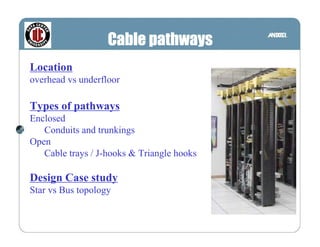
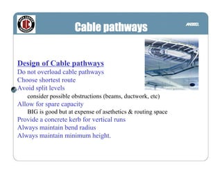
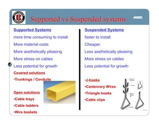
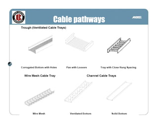
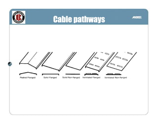
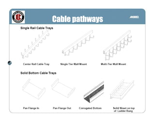
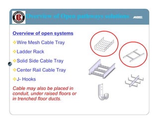

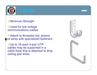
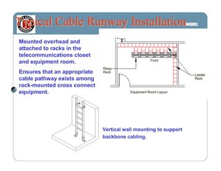
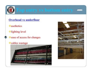


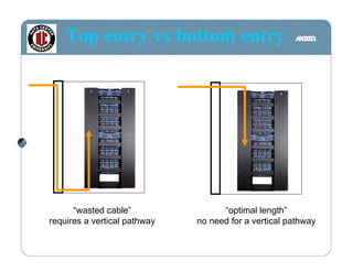


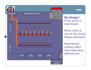


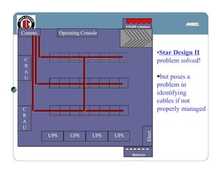


The document discusses various types of cable pathways for data center design including overhead vs underfloor installation. It covers enclosed pathways like conduits and trunkings as well as open pathways such as cable trays, J-hooks, and triangle hooks. The document also provides a case study comparing bus topology vs star topology for cable pathway design and discusses best practices for pathway installation.


