Series circuits ad parallel circuits
•Download as DOCX, PDF•
1 like•736 views

assiginement

Recommended
More Related Content
What's hot
What's hot (20)
Viewers also liked
Similar to Series circuits ad parallel circuits
Similar to Series circuits ad parallel circuits (20)
Recently uploaded
Recently uploaded (20)
Series circuits ad parallel circuits
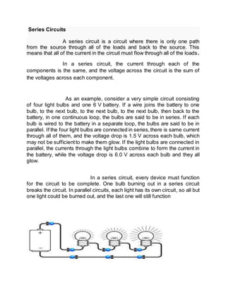
- 1. Series Circuits A series circuit is a circuit where there is only one path from the source through all of the loads and back to the source. This means that all of the current in the circuit must flow through all of the loads. In a series circuit, the current through each of the components is the same, and the voltage across the circuit is the sum of the voltages across each component. As an example, consider a very simple circuit consisting of four light bulbs and one 6 V battery. If a wire joins the battery to one bulb, to the next bulb, to the next bulb, to the next bulb, then back to the battery, in one continuous loop, the bulbs are said to be in series. If each bulb is wired to the battery in a separate loop, the bulbs are said to be in parallel. If the four light bulbs are connected in series,there is same current through all of them, and the voltage drop is 1.5 V across each bulb, which may not be sufficientto make them glow. If the light bulbs are connected in parallel, the currents through the light bulbs combine to form the current in the battery, while the voltage drop is 6.0 V across each bulb and they all glow. In a series circuit, every device must function for the circuit to be complete. One bulb burning out in a series circuit breaks the circuit. In parallel circuits, each light has its own circuit, so all but one light could be burned out, and the last one will still function
- 2. Explanation: Let's start with a series circuit consisting of three resistors and a single battery: The first principle to understand about series circuits is that the amount of current is the same through any component in the circuit. This is because there is only one path for electrons to flow in a series circuit, and because free electrons flow through conductors like marbles in a tube, the rate of flow (marble speed) at any point in the circuit (tube) at any specific point in time must be equal. From the way that the 9 volt battery is arranged, we can tell that the electrons in this circuit will flow in a counter-clockwise direction, from point 4 to 3 to 2 to 1 and back to 4. However, we have one source of voltage and three resistances. How do we use Ohm's Law here? An important caveat to Ohm's Law is that all quantities (voltage, current, resistance, and power) must relate to each other in terms of the same two points in a circuit. For instance, with a single-battery, single-resistor circuit, we could easily calculate any quantity because they all applied to the same two points in the circuit:
- 3. Since points 1 and 2 are connected together with wire of negligible resistance, as are points 3 and 4, we can say that point 1 is electrically commonto point 2, and that point 3 is electrically common to point 4. Since we know we have 9 volts of electromotive force between points 1 and 4 (directly across the battery), and since point 2 is common to point 1 and point 3 commonto point 4, we must also have 9 volts between points 2 and 3 (directly across the resistor). Therefore, we can apply Ohm's Law (I = E/R) to the current through the resistor, because we know the voltage (E) across the resistor and the resistance (R) of that resistor. All terms (E, I, R) apply to the same two points in the circuit, to that same resistor, so we can use the Ohm's Law formula with no reservation. However, in circuits containing more than one resistor, we must be careful in how we apply Ohm's Law. In the three-resistorexample circuit below, we know that we have 9 volts between points 1 and 4, which is the amount of electromotive force trying to push electrons through the series combination of R1, R2, and R3. However, we cannot take the value of 9 volts and divide it
- 4. by 3k, 10k or 5k Ω to try to find a current value, because we don't know how much voltage is across any one of those resistors,individually. The figure of 9 volts is a total quantity for the whole circuit, whereas the figures of 3k, 10k, and 5k Ω are individual quantities for individual resistors. If we were to plug a figure for total voltage into an Ohm's Law equation with a figure for individual resistance,the result would not relate accurately to any quantity in the real circuit.
- 5. Parallel Circuits A parallel circuit is one that has two or more paths for the electricity to flow , the loads are parallel to each other. If the loads in this circuit were light bulbs and one blew out, there is still current flowing to the others because they are still in a direct path from the negative to positive terminals of the battery. A Parallel circuit is one with several different paths for the electricity to travel. It's like a river that has been divided up into smaller streams, however, all the streams come back to the same point to form the river once again. The parallel circuit has very different characteristics than a series circuit. For one, the total resistance of a Parallel Circuit is NOT equal to the sum of the resistors (like in a series circuit). The total resistance in a parallel circuit is always less than any of the branch resistances. Adding more parallel resistances to the paths causes the total resistance in the circuit to decrease. As you add more and more branches to the circuit the total current will increase because Ohm's Law states that the lower the resistance, the higher the current.
- 6. Explanation: Let's start with a parallel circuit consisting of three resistors and a single battery: The first principle to understand about parallel circuits is that the voltage is equal across all components in the circuit. This is because there are only two sets of electrically common points in a parallel circuit, and voltage measured between sets of commonpoints must always be the same at any given time. Therefore,in the above circuit, the voltage across R1 is equal to the voltage across R2 which is equal to the voltage across R3 which is equal to the voltage across the battery. This equality of voltages can be represented in another table for our starting values:
- 7. Just as in the case of series circuits, the same caveat for Ohm's Law applies: values for voltage, current, and resistance must be in the same context in order for the calculations to work correctly. However, in the above example circuit, we can immediately apply Ohm's Law to each resistor to find its current because we know the voltage across each resistor (9 volts) and the resistance of each resistor:
- 8. At this point we still don't know what the total current or total resistance for this parallel circuit is, so we can't apply Ohm's Law to the rightmost ("Total") column. However, if we think carefully about what is happening it should become apparent that the total current must equal the sum of all individual resistor ("branch") currents:
- 9. As the total current exits the negative (-) battery terminal at point 8 and travels through the circuit, some of the flow splits off at point 7 to go up through R1, some more splits off at point 6 to go up through R2, and the remainder goes up through R3. Like a river branching into several smaller streams, the combined flow rates of all streams must equal the flow rate of the whole river. The same thing is encountered where the currents through R1, R2, and R3 join to flow back to the positive terminal of the battery (+) toward point 1: the flow of electrons from point 2 to point 1 must equal the sum of the (branch) currents through R1, R2, and R3.