
Recommended
More Related Content
Similar to 1. What two conditions must be met before an entity can be classif.docx
Similar to 1. What two conditions must be met before an entity can be classif.docx (20)
More from jackiewalcutt
More from jackiewalcutt (20)
Recently uploaded
Recently uploaded (20)
1. What two conditions must be met before an entity can be classif.docx
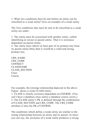
- 1. 1. What two conditions must be met before an entity can be classified as a weak entity? Give an example of a weak entity. The Two conditions that must be met to be classified as a weak entity are under : 1. The entity must be associated with another entity ,called identifying or owner or parent entity. That it is existence dependent on parent entity. 2. The entity must inherit at least part of its primary key from its parent entity.Only than it would be a valid and strong primary key. CRS_NAME CRS_CODE CONNECT CLASSNAME CLASS_SECTION Class Course For example, the (strong) relationship depicted in the above Figure shows a weak CLASS entity: 1. CLASS is clearly existence-dependent on COURSE. (You can’t have a database class unless a database course exists.) 2. The CLASS entity’s PK is defined through the combination of CLASS_SECTION and CRS_CODE. The CRS_CODE attribute is also the PK of COURSE. The conditions which define a weak entity are similar to the strong relationship between an entity and its parent. In short, you can say, the existence of a weak entity produces a strong
- 2. relationship. And if the entity is strong, its relationship to the other entity is weak. Whether or not an entity to be weak it is usually dependent on the database designer’s decisions. For instance, if the database designer had decided to use a single-attribute as shown in the text’s Figure below., the CLASS entity would be strong. (The CLASS entity’s PK is CLASS_CODE, which is not derived from the COURSE entity.) In this case, the relationship between COURSE and CLASS is weak. However, regardless of how the designer classifies the relationship – weak or strong – CLASS is always existence-dependent on COURSE. CONNECT CLASS_CODE Class CRS_NAM E Course CRS_CODE cr 2. What is a strong (or identifying) relationship, and how is it depicted in a Crow’s Foot ERD? A strong relationship exists / occurs when an entity is existence-dependent on another entity and inherits at least part of its primary key from that entity. The Visio Professional software shows the strong relationship as a solid line. In other words, a strong relationship exists when a weak entity is related to its parent entity. As discussed in the above question Class , the weak entity is related to strong entity Course with the help
- 3. of a relationship called CONNECT which is a showing /identifying a strong relationship. As shown in the above figure a strong relationship is represented by two decision boxes… One inside another embedded together represent this. 3. Given the business rule “an employee may have many degrees,” discuss its effect on attributes, entities, and relationships. (Hint: Remember what a multivalued attribute is and how it might be implemented.) Suppose that an employee has the following degrees: BBA, Ph.D , and MBA. These degrees could be stored in a single string as a multivalued attribute named EMP_DEGREE in an EMPLOYEE table such as the one shown next: EMP_NUM EMP_LNAME EMP_DEGREE 123 Carter BS, BBA 124 O’Shanski BBA, MBA, Ph.D. 125 Jones BS 126 Ortez BS, MS Although the preceding solution has no obvious design flaws, but it is likely to yield reporting problems. For example, suppose one want to get a count for all employees who have BBA degrees. He could, of course, can do an “in-string” search to find all of the BBA values within the EMP_DEGREE strings.
- 4. But such a solution is cumbersome i.e. time consuming from a reporting point of view. Query simplicity is a valuable thing for application developers – and to end users who like maximum query execution speeds. Database designers have to pay some attention to the competing database interests that exist in the data environment by all. One – very poor and old – solution is to create a field for each expected value. This “solution is shown next: EMP_NUM EMP_LNAME EMP_DEGREE1 EMP_DEGREE2 EMP_DEGREE3 123 Carter AA BBA 124 O’Shanski BBA MBA Ph.D. 125 Jones AS 126 Ortez BS MS
- 5. But this “solution yields nulls for all employees who have fewer than three degrees. And if even one employee earns a fourth degree, the table structure must be altered to accommodate the new data value. (One piece of evidence of poor design is the need to alter table structures in response to the need to add data of an existing type.) In addition, the query simplicity is not enhanced by the fact that any degree can be listed in any column. For example, a BA degree might be listed in the second column, after an “associate of arts (AA) degree has been entered in EMP_DEGREE1. One might simplify the query environment by creating a set of attributes that define the data entry, thus producing the following results: EMP_NUM EMP_LNAME EMP_AA EMP_AS EMP_BA EMP_BS EMP_BBA EMP_MS EMP_MBA EMP_PhD 123 Carter X X 124 O’Shanski
- 6. X X X 125 Jones X 126 Ortez X X This “solution” clearly proliferates the nulls at an ever- increasing pace. So not a good solution for the database designer . The only reasonable solution is to create a new DEGREE entity that stores each degree in a separate record, this producing the following tables. (There is a 1:M relationship between EMPLOYEE and DEGREE). Note that the EMP_NUM can occur
- 7. more than once in the DEGREE table. The DEGREE table’s PK is EMP_NUM + DEGREE_CODE. This solution also makes it possible to record the date on which the degree was earned, the institution from which it was earned, and so on. Table name: EMPLOYEE EMP_NUM EMP_LNAME 123 Carter 124 O’Shanski 125 Jones 126 Ortez Table name: DEGREE EMP_NUM DEGREE_CODE DEGREE_DATE DEGREE_PLACE 123 AA May-1999 Lake Sumter CC 123 BBA Aug-2004 U. of Georgia
- 8. 124 BBA Dec-1990 U. of Toledo 124 MBA May-2001 U. of Michigan 124 Ph.D. Dec-2005 U. of Tennessee 125 AS Aug-2002 Valdosta State 126 BS Dec-1989 U. of Missouri 126 MS May-2002 U. of Florida Note that this solution leaves no nulls, produces a simple query environment, and makes it unnecessary to alter the table structure when employees earn additional degrees. Thus making a new table is a good and result giving and less time consuming solution. 4. What is a composite entity, and when is it used? A composite entity is generally used to transform M:N relationships into 1:M relationships. A composite entity, also known as a bridge entity, is one that has a primary key
- 9. composed of multiple attributes. The PK attributes are inherited from the entities that it relates to one another. A composite entity is defined by the fact that at least one of the PK attributes is also a foreign key. For instance,consider the above question.Here we have created DEGREE table.In this the primary key attributes are EMP_NUM and DEGREE_CODE which is an example of composite entity. 5. Suppose you are working within the framework of the conceptual model in Figure Q4.5. Figure Q4.5 The Conceptual Model for Question 5 Given the conceptual model in Figure Q4.5: a. Write the business rules that are reflected in it. In this case, the business rules are derived from the ERD in a “reverse-engineering” procedure designed to document the database design. In a real world database design situation, the ERD is generated on the basis of business rules that are written before the first entity box is drawn. Following business rules can be identified :
- 10. 1. A customer can own many cars. 2. Some customers do not own cars. 3. A car is owned by one and only one customer. 4. A car may generate one or more maintenance records. 5. Each maintenance record is generated by one and only one car. 6. Some cars have not (yet) generated a maintenance procedure. 7. Each maintenance procedure can use many parts. (Comment: A maintenance procedure may include multiple maintenance actions, each one of which may or may not use parts. For example, 10,000-mile check may include the installation of a new oil filter and a new air filter. But tightening an alternator belt does not require a part.) 8. A part may be used in many maintenance records. (Comment: Each time an oil change is made, an oil filter is used. Therefore, many oil filters may be used during some period of time. Naturally, you are not using the same oil filter each time – but the part classified as “oil filter” shows up in many maintenance records as time passes.) Note that the apparent M:N relationship between MAINTENANCE and PART has been resolved through the use of the composite entity named MAINT_LINE. The MAINT_LINE entity ensures that the M:N relationship between MAINTENANCE and PART has been broken up to produce the two 1:M relationships shown in business rules 9 and 10. 9. Each maintenance procedure generates one or more maintenance lines. 10. Each part may appear in many maintenance lines. Use the following two tables to show some sample data entries. For example, take a look at the (simplified) contents of the following MAINTENANCE and LINE tables and note that the MAINT_NUM 10001 occurs three times in the LINE table: Sample MAINTENANCE Table Data
- 11. MAINT_NUM MAINT_DATE 10001 15-Mar-2008 10002 15-Mar-2008 10003 16-Mar-2008 Sample LINE Table Data MAINT_NUM LINE_NUM LINE_DESCRIPTION LINE_PART LINE_UNITS 10001 1 Replace fuel filter FF-015 1 10001 2 Replace air filter AF-1187 1 10001 3 Tighten alternator belt NA 0 10002 1 Replace taillight bulbs BU-2145 2 10003
- 12. 1 Replace oil filter OF-2113 1 10003 2 Replace air filter AF-1187 1 b. Identify all of the cardinalities. The Visio-generated Crow’s Foot ERD, shown in Figure Q4.5, does not show cardinalities directly. Instead, the cardinalities are implied through the Crow’s Foot symbols. You might write the cardinality (0,N) next to the MAINT_LINE entity in its relationship with the PART entity to indicate that a part might occur “N” times in the maintenance line entity or that it might never show up in the maintenance line entity. The latter case would occur if a given part has never been used in maintenance. 6. What is a recursive relationship? Given an example. A recursive relationship exists when an entity is related to itself.That it is when an entity call or use itself in its query. For example, a COURSE may be a prerequisite to a COURSE. Than it would be recursive relationship. 7. How would you (graphically) identify each of the following ERM components in a Crow’s Foot model? The answers to questions (a) through (d) are illustrated with the help of Figure Q4.7. FIGURE Q4.7 Crow’s Foot ERM Components
- 13. a. an entity An entity is represented by a rectangle containing the entity name. (Remember that, in ER modeling, the word "entity" actually refers to the entity set.) The Crow’s Foot ERD – as represented in Visio Professional – does not distinguish among the various entity types such as weak entities and composite entities. Instead, the Crow’s Foot ERD uses relationship types – strong or weak – to indicate the nature of the relationships between entities. For example, a strong relationship indicates the existence of a weak entity. A composite entity is defined by the fact that at least one of the PK attributes is also a foreign key. Therefore, the Visio Crow’s Foot ERD’s composite and weak entities are not differentiated – whether or not an entity is weak or composite depends on the definition of the business rule(s) that describe the relationships. In any case, two conditions must be met before an entity can be classified as weak: 1. The entity must be existence-dependent on its parent entity 2. The entity must inherit at least part of its primary key from its parent entity. b. the cardinality (0,N) Cardinalities are implied through the use of Crow’s Foot symbols. For example, note the implied (0,N) cardinality in Figure. c. a weak relationship
- 14. A weak relationship exists when the PK of the related entity does not contain at least one of the PK attributes of the parent entity. For example, if the PK of a COURSE entity is CRS_CODE and the PK of the related CLASS entity is CLASS_CODE, the relationship between COURSE and CLASS is weak. (Note that the CLASS PK does not include the CRS_CODE attribute.) A weak relationship is indicated by a dashed line in the (Visio) ERD. d. a strong relationship A strong relationship exists when the PK of the related entity contains at least one of the PK attributes of the parent entity. For example, if the PK of a COURSE entity is CRS_CODE and the PK of the related CLASS entity is CRS_CODE + CLASS_SECTION, the relationship between COURSE and CLASS is strong. (Note that the CLASS PK includes the CRS_CODE attribute.) A strong relationship is indicated by a solid line in the (Visio) ERD. 8. Write the ten cardinalities that are appropriate for this ERD. The cardinalities are indicated in Figure Q4.17sol. FIGURE Q4.17sol The Cardinalities 9. Write the business rules reflected in this ERD. The following business rules are reflected in the ERD: · A store may place many orders. (Note the use of “may” – which is reflected in the ORDER optionality.)
- 15. · An order must be placed by a store. (Note that STORE is mandatory to ORDER. In this ERD, the order environment apparently reflects a wholesale environment.) · An order contains at least one order line. (Note that ORDER_LINE is mandatory to ORDER, and vice-versa.) · Each order line is contained in one and only one order. (Discussion: Although a given item – such as a hammer – may be found in many orders, a specific hammer sold to a specific store is found in only one order.) · Each order line has a specific product written in it. · A product may be written in many orders. (Discussion: Many stores can order one or more specific products, but a product that is not in demand may never be sold to a store and will, therefore, not show up in any order line -- note that ORDER_LINE is optional to PRODUCT. Also, note that each order line may indicate more than one of a specific item. For example, the item may be “hammer” and the number sold may be 1 or 2, or 500. The ORDER_LINE entity would have at least the following attributes: ORDER_NUM, ORDLINE_NUM, PROD_CODE, ORDLINE_PRICE, ORDLINE_QUANTITY. The ORDER_LINE composite PK would be ORDER_NUM + ORDLINE_NUM. You might add the derived attribute ORDLINE_AMOUNT, which would be the result of multiplying ORDLINE_PRICE and ORDLINE_QUANTITY.) · A store may employ many employees. (Discussion: A new store may not yet have any employees, yet the database may already include the new store information … location, type, and so on. If you made the EMPLOYEE entity mandatory to STORE, you would have to create an employee for that store before you had even hired one.) · Each employee is employed by one (and only one) store. · An employee may have one or more dependents. (Discussion: You cannot require an employee to have dependents, so DEPENDENT is optional to EMPLOYEE. Note the use of the word “may” in the relationship.) · A dependent must be related to an employee. (Discussion: It
- 16. makes no sense to keep track of dependents of people who are not even employees. Therefore, EMPLOYEE is mandatory to DEPENDENT.) 10. What two attributes must be contained in the composite entity between STORE and PRODUCT? Use proper terminology in your answer. The composite entity must at least include the primary keys of the entities it references. The combination of these attributes may be designated to be the composite entity's (composite) primary key. Each of the (composite) primary key's attributes is a foreign key that references the entities for which the composite entity serves as a bridge. As you discuss the model in Figure Q4.17sol, note that an order is represented by two entities, ORDER and ORDER_LINE. Note also that the STORE’s 1:M relationship with ORDER and the ORDER’s 1:M relationship with ORDER_LINE reflect the conceptual M:N relationship between STORE and PRODUCT. The original business rules probably read: · A store can order many products · A product can be ordered by many stores. 11. Describe precisely the composition of the DEPENDENT weak entity’s primary key. Use proper terminology in your answer. The DEPENDENT entity will have a composite PK that includes the EMPLOYEE entity’s PK and one of its attributes. For example, if the EMPLOYEE entity’s PK is EMP_NUM, the DEPENDENT entity’s PK might be EMP_NUM + DEP_NUM.
- 17. Simplified Crow’s Foot entity box (no attribute component.) STUDENT Crow’s Foot entity box (attribute component included.) Crow’s Foot connectivity symbol, implied (0,N) cardinality. A weak relationship A strong relationship CRS_NAME CRS_NAME STUDENT STU_NUM (PK) STU_LNAME STU_FNAME STU_INITIAL DEPT_CODE (FK) Simplified Crow’s Foot entity box (no attribute component.) STUDENT Crow’s Foot entity box (attribute component included.) Crow’s Foot connectivity symbol, implied (0,N) cardinality. A weak relationship A strong relationship BMIS 325 CMS Project: Phase I Instructions Part A: Background Information:
- 18. CMS Systems, Inc. is a company that provides information systems consulting services to companies in the telecom industry in the United States and the United Kingdom. Due to its success, CMS is hoping to expand its operations into other parts of Europe. Despite its large size, CMS currently uses a manual/spreadsheet-based process for maintaining employee and client data. Management has now decided to implement a company-wide database that will serve all of its operations. CMS currently employs 1,500 individuals (900 in the US and 600 in the UK) who serve as systems analysts, developers, managers, testers, maintenance engineers, accountants, lawyers, and sales representatives. Each employee has a first name, last name, unique CMS ID, office location, email address, salary, title, level, and supervisor. CMS has more than 200 clients in the US and UK. Clients are identified by various names by CMS associates. As such, they represent a source of confusion for the company. The legal department refers to clients by their legal names, while the sales and consulting departments refer to them by a more common name. One example is British Telecom. CMS’s legal team uses its full legal name “British Telecom, Ltd.,” while the sales force and consultants refer to it as “BT.” The accounting department uses a mixture of legal and common names to identify clients. Thus, to avoid confusion, both legal and common names must be available to all users. Data that must be kept about clients include client names, an address (city, state, zip, country), and contact information (discussed below). Clients have contacts within their companies that CMS employees must utilize. For example, the accounting department must know a client’s billing contact in order to know where to send the bill. Maintenance engineers must know a client’s systems engineering contact to know with whom to speak when a problem arises. CMS’s sales representatives must know a client’s sales contact to determine who is responsible for the buying decisions at a client site. Although only these three contact “types” are currently used by CMS, it is foreseeable that
- 19. additional contact types might be useful as the company expands into other parts of the world. Currently, a client has only one billing contact, one systems engineering contact, and one sales contact at any given time. This structure is not expected to change (that is, more than one billing contact per client as of a particular point in time is not anticipated); however, it is important to retain all contact information over time. That is, when one contact is replaced by another contact, it is essential to retain information about the original contact. For example, assume an invoice is sent to Contact A, who is later replaced by Contact B. If the invoice is lost, CMS must have an audit trail to show that it was sent to Contact A (who was the known contact for the client at that time). Clients can have one or more contracts with CMS to provide a variety of consulting services. For example, a single client might have one contract for maintenance of an existing system and also have another contract (sometimes called a work order by the sales force) for the development of a new system. Some clients are billed based upon negotiated contracts, which stipulate a pre-determined amount for charges regardless of the number of hours that employees actually work on the contracts. Such contracts are called “fixed price” contracts. Other clients are billed based on the total number of hours provided by CMS employees multiplied by a rate per employee type per employee hour. These arrangements are called “T&M – Time and Materials” contracts. T&M contracts often specify a maximum number of hours for which the client is willing to pay. CMS managers must ensure that when these maximum (cap) amounts are exceeded, the clients are not billed for such additional hours. For T&M contracts, the rate per hour for each consultant is determined by the employee’s level of expertise. For example, a client might pay $100/hour for an employee who is at the level of Systems Analyst I. That same client would pay $250/hour for an employee designated as a Manager Level II. Although T&M and Fixed Price contracts are the only two types
- 20. of contracts currently used by CMS, it is likely that other types of contracts will be used in the near future. All CMS employees must keep a record of the time they spend working for each client. Because employees can work for more than one client and perform different functions for each client, CMS utilizes “project management” to keep track of employee assignments to client contracts. Employees can be assigned to many different projects throughout their tenure. They also can be assigned to more than one project at a given time. In fact, it is not unusual for an employee to spend time on two or more different projects within the same day. Likewise, projects can consist of many different employees. Project assignments change over time. For example, Employee “A” may work on Project “X” during January, and in February, that same employee may be reassigned to Project “Y”. It is important to maintain records of the dates for which each employee is assigned to each project. Additionally, each project has a manager who oversees its progress and ensures that contracts are fulfilled and profitable (e.g. US project managers try to prevent hours worked in excess of the maximum allowed by a fixed price contract). Just as a client can have more than one contract with CMS, a contract can consist of more than one project. For example, a contract for the development of a new system could be fulfilled in multiple phases. Phase I could include implementation at one client site using a group of consultants in close proximity to that site. Phase II could include implementation at a different site with a potentially different set of consultants. Both of these phases are considered separate projects, even though they are governed by the same contract. To further complicate matters, if such a contract specifies a maximum number of hours for overall implementation, the project managers of each project will have to agree how to split up the cap amounts between the two projects and maintain appropriate data about the split. The number of hours worked for each employee on each project must be recorded on a daily basis. Employees currently log their
- 21. time using an Excel worksheet. An example of this worksheet is presented below. Notice that the employee’s supervisor is listed on the worksheet. This supervisor may or may not be the same person as the project manager. Each employee is assigned to one supervisor, and each supervisor manages one or more employees. The concepts of supervisor and project manager have completely different meanings at CMS. A supervisor manages an employee with respect to evaluations, vacation requests, raises, etc. A project manager manages a project, allocating the time of employees assigned to the project. A project manager is not required to sign off on an employee’s timesheet. A supervisor, however, is required to approve his employees’ timesheets by placing his initials beside his name. Part A Deliverable: For this phase, you are required to create an ER Diagram that will facilitate the development of CMS’s company-wide database. It should be created using ER Assistant and include entities and attributes, relationships, and accompanying notes. You should take a screen shot of your ERD while it is displayed in ER Assistant and paste the screen shot into a Word document. Make sure that the ERD fits on a single sheet and is legible. Accompanying notes should be included on a separate sheet of the document. Name this Word document CMS Project Part A - [your last name followed by your first initial]. Example: CMS Project Part A – SmithJ.doc The scope of the database includes all entities referenced above. The first goal of this phase of development is to support a timekeeping system that will replace the spreadsheet process illustrated above. Note that you will not actually create the timekeeping system. You are responsible only for designing the database that will be used by the system. Part B: Background:
- 22. After much deliberation, CMS has decided to broaden its operations by expanding into various parts of Europe and also Canada. It plans to recruit employees from Canada, Italy, France, and Ireland. Each of these countries offers different benefit packages. Presently, under the manual spreadsheet system, human resource personnel have to maintain only two types of benefit allotments. In the newly expanded company, this manual process will be unmanageable. The following table lists the different benefit packages in each country. Some characteristics are unique to each country while others are unique to a region. Region Country Holidays WeeklyHours VacationDaysAllowed North America US 11 40 10 North America Canada 12 40 15 Europe UK 10 38 10 Europe France 14 38 10
- 23. Europe Ireland 10 38 15 Europe Italy 9 38 20 In the same manner that employees must track the time they spend working on projects, they must also log the days they use as holidays and vacation. Below is a sample timesheet for recording benefit time taken. Note that this benefit section exists on the same timesheet that is used to log hours to projects, but benefits are not related to projects. In addition to the need to accommodate benefit tracking in the new database, a change has occurred since the last iteration. In Part A, CMS stated, “a client has only one billing contact, one systems engineering contact, and one sales contact at any given time. This structure is not expected to change (that is, more than one billing contact per client as of a particular point in time is not anticipated)”. Recent developments from a newly acquired client have caused this assertion to no longer be true. France Telemobile, Inc. is a new client in France and has three different systems engineering contacts to support its one contract with CMS. Thus, a change in initial design is required. Finally, CMS is implementing two new types of contracts, Maintenance and License, to be added to its list of possible contracts. Currently, maintenance is included as part of an initial work order. In keeping with the rules of Accounting and revenue recognition for software providers, maintenance is an important
- 24. feature of a contract and has special rules that affect how much revenue can be recognized for licenses. To simplify its procedures, the company will be issuing separate contracts for maintenance to clearly distinguish between license revenue, which can be recognized at the time of system delivery, and maintenance revenue, which in most cases must be recognized over the duration of the maintenance agreement. Many of the features of CMS’s custom work orders have evolved into a standard set of templates that will be sold as a package to other companies to expand CMS’s client-base. Therefore, the company has created various products that incorporate the most widely used features of its custom development initiatives. The products are called TeleTrak-BP, TeleTrak-FM, and TeleSource. Each product will be sold as an out-of-the-box solution to tracking usage and subscriptions in the Telecom industry. Each product will be sold under a License contract. Presently, a license contract will be issued for exactly one product, but it is possible that a license agreement will be written in the future that will cover multiple products as new products are developed. Part B Deliverable: Using ER Assistant, modify your original ERD to accommodate the requirement to allow more than one instance of a given contact type per contract. Also, include new entities and relationships to support benefit tracking in all countries. Depending on your initial design, you may or may not have to modify your ERD to accommodate the new contract types (License and Maintenance). You will also have to account for the introduction of products in the business model. In a separate Word document, take a screenshot of your revised ERD and paste it in. Include accompanying notes. After completing your new ER Diagram, convert the diagram into tables with primary keys and foreign keys as appropriate. Use SQL Server to create your tables. Be sure to enforce referential integrity in your CREATE TABLE statements using
- 25. “on delete”, “on update”, etc. where appropriate. As in Part A, your ERD screenshot should be able to legibly fit on a single sheet in the Word document. To receive credit for your table conversions, include the SQL queries used to generate the tables and paste them into your Word document. Also execute the following command for each table and include results in your document: exec sp_help [table name] Name this document CMS Project Part B – [your last name followed by your first initial]. Screenshots are required each SQL, DML, DDL, and DCL statement for a grade to be given. Note, one screenshot is not the idea; however, multiple screenshots along the way is the goal. Using the link provided in Blackboard, upload your 2 documents for Phase I of this project by 11:59 p.m. (ET) on Monday of Module/Week 5. Page 1 of 6 CMS Project: Phase II Instructions In this phase, you will create tables based upon the ERD and SQL code below. You will then populate each table with the data presented below. Finally, you will create queries that will be used to support reports for Accounting and Management. You will not actually create the reports in a GUI environment– only the queries that will serve as the basis for the reports. Screenshots are required for a grade to be given. One screenshot is not the idea; however, multiple screenshots along the way is the goal. Background: The following ERD will be used as the basis for this Phase. Part A: Table Creation and Data Loading
- 26. Instructions: Create a new database in SQL Server and run the following CREATE TABLE commands. Note that you must run the CREATE TABLE statements in the order presented (and load the data in the order presented) to avoid conflicts resulting from foreign key constraints. Additional instructions for materials to turn in for this phase of your project are included at the end of this specification document. CREATE TABLE Regions (RegionID int not null, RegionAbbreviation varchar(4), RegionName varchar(100), CONSTRAINT PK_Regions PRIMARY KEY (RegionID)) CREATE TABLE Countries (CountryID int not null, CountryName varchar(50), WeeklyHours int, Holidays int, VacationDays int, RegionID int, CONSTRAINT PK_Countries PRIMARY KEY (CountryID), CONSTRAINT FK_CountriesRegions FOREIGN KEY (RegionID) References Regions) CREATE TABLE EmployeeTitles (TitleID int not null, Title varchar(15), CONSTRAINT PK_EmpTitles PRIMARY KEY (TitleID)) CREATE TABLE BillingRates (TitleID int not null, Level int not null, Rate float, CurrencyName varchar(5), CONSTRAINT PK_BillingRates PRIMARY KEY (TitleID,
- 27. Level), CONSTRAINT FK_BillingRatesTitles FOREIGN KEY (TitleID) References EmployeeTitles) CREATE TABLE Employees (EmpID int not null, FirstName varchar(30), LastName varchar(30), Email varchar(50), Salary decimal(10,2), TitleID int, Level int, SupervisorID int, CountryID int, CONSTRAINT PK_Employees PRIMARY KEY (EmpID), CONSTRAINT FK_EmployeesCountries FOREIGN KEY (CountryID) References Countries, CONSTRAINT FK_EmployeesEmpTitles FOREIGN KEY (TitleID) References EmployeeTitles, CONSTRAINT FK_EmployeeSupervisors FOREIGN KEY (SupervisorID) References Employees) CREATE TABLE ContactTypes (ContactTypeID int not null, ContactType varchar(30) CONSTRAINT PK_ContactTypes PRIMARY KEY (ContactTypeID)) CREATE TABLE ContractTypes (ContractTypeID int not null, ContractType varchar(30) CONSTRAINT PK_ContractTypes PRIMARY KEY (ContractTypeID)) CREATE TABLE BenefitTypes (BenefitTypeID int not null,
- 28. BenefitType varchar(30) CONSTRAINT PK_BenefitTypes PRIMARY KEY (BenefitTypeID)) CREATE TABLE Clients (ClientID int not null, LegalName varchar(50), CommonName varchar(50), AddrLine1 varchar(50), AddrLine2 varchar(50), City varchar(25), State_Province varchar(25), Zip varchar(9), CountryID int, CONSTRAINT PK_Clients PRIMARY KEY (ClientID), CONSTRAINT FK_ClientsCountries FOREIGN KEY (CountryID) REFERENCES Countries) CREATE TABLE Contacts (ContactID int not null, FirstName varchar(50), LastName varchar(50), AddrLine1 varchar(50), AddrLine2 varchar(50), City varchar(25), State_Province varchar(25), Zip varchar(9), CountryID int, ContactTypeID int, CONSTRAINT PK_Contacts PRIMARY KEY (ContactID), CONSTRAINT FK_ContactsCountries FOREIGN KEY (CountryID) REFERENCES Countries) CREATE TABLE ContractTypes
- 29. (ContractTypeID int not null, ContractTypeDesc varchar(50), CONSTRAINT PK_ContractTypes PRIMARY KEY (ContractTypeID)) CREATE TABLE Contracts (ContractID int not null, ContractDesc varchar(100), ClientID int, ContractTypeID int, CONSTRAINT PK_Contracts PRIMARY KEY (ContractID), CONSTRAINT FK_ContractsClients FOREIGN KEY (ClientID) REFERENCES Clients, CONSTRAINT FK_ContractsContractTypes FOREIGN KEY (ContractTypeID) REFERENCES ContractTypes) CREATE TABLE ContractsContacts (ContractID int not null, ContactID int not null, CONSTRAINT PK_ContractsContacts PRIMARY KEY (ContractID, ContactID), CONSTRAINT FK_CC_Contracts FOREIGN KEY (ContractID) REFERENCES Contracts, CONSTRAINT FK_CC_Contacts FOREIGN KEY (ContactID) REFERENCES Contacts) CREATE TABLE Projects (ProjectID int not null, ProjectName varchar(50), HourCapAmount decimal(10,2), ProjectManagerID int, ContractID int, CONSTRAINT PK_Projects PRIMARY KEY (ProjectID), CONSTRAINT FK_ProjectsEmployees FOREIGN KEY (ProjectManagerID) REFERENCES Employees,
- 30. CONSTRAINT FK_ProjectsContracts FOREIGN KEY (ContractID) REFERENCES Contracts) CREATE TABLE EmployeesProjects (EmpID int not null, ProjectID int not null, StartDate smalldatetime, EndDate smalldatetime, CONSTRAINT PK_EmployeesProjects PRIMARY KEY (EmpID, ProjectID), CONSTRAINT FK_EP_Employees FOREIGN KEY (EmpID) REFERENCES Employees, CONSTRAINT FK_EP_Projects FOREIGN KEY (ProjectID) REFERENCES Projects) CREATE TABLE Timesheets (TimesheetID int not null, SupervisorApproveDate smalldatetime, CONSTRAINT PK_Timesheets PRIMARY KEY (TimesheetID)) CREATE TABLE WorkHours (EmpID int not null, ProjectID int not null, WH_Day int not null, WH_Month int not null, WH_Year int not null, HoursWorked float, TimesheetID int, CONSTRAINT PK_WorkHours PRIMARY KEY (EmpID, ProjectID, WH_Day, WH_Month, WH_Year), CONSTRAINT FK_WorkHoursEmployees FOREIGN KEY (EmpID) REFERENCES Employees, CONSTRAINT FK_WorkHoursProjects FOREIGN KEY
- 31. (ProjectID) REFERENCES Projects, CONSTRAINT FK_WorkHoursTimesheets FOREIGN KEY (TimesheetID) REFERENCES Timesheets) CREATE TABLE BenefitsTaken (EmpID int not null, BenefitTypeID int not null, BT_Day int not null, BT_Month int not null, BT_Year int not null, HoursTaken float, TimesheetID int, CONSTRAINT PK_BenefitsTaken PRIMARY KEY (EmpID, BenefitTypeID, BT_Day, BT_Month, BT_Year), CONSTRAINT FK_BenefitsTakenEmployees FOREIGN KEY (EmpID) REFERENCES Employees, CONSTRAINT FK_BenefitsTakenBenefitTypes FOREIGN KEY (BenefitTypeID) REFERENCES BenefitTypes, CONSTRAINT FK_BenefitsTakenTimesheets FOREIGN KEY (TimesheetID) REFERENCES Timesheets) Data Section The following information is currently maintained in various spreadsheets throughout CMS. Data from these spreadsheets must be uploaded into your newly created tables before the database can be considered operational. REGIONS ID Abbr. Region Name 1 NAR North America 2 CALA Central and Latin America 3 APAC Asia and Pacific 4 EMEA Europe, Middle East, and Africa COUNTRIES
- 32. ID Country Name Weekly Hours Holidays Vacation Days Region 1 United States 40 11 10 NAR 2 Canada 40 12 15 NAR 3 United Kingdom 38 10 10 EMEA 4 France 38 14 10 EMEA 5 Ireland 38 10 15 EMEA 6 Italy 35 9 20 EMEA 7 Thailand 40 17 20 APAC 8 Singapore 40 17 21 APAC 9 Panama 40 12 15 CALA BENEFIT TYPES ID Benefit Type Name 1 Vacation 2 Holiday 3 Jury Duty 4 Maternity Leave 5 Paternity Leave 6 Military Duty CONTACT TYPES ID Contact Type Name 1 Systems Engineer 2 Sales 3 Billing CONTRACT TYPES
- 33. ID Contract Type Name 1 Maintenance 2 Fixed Price 3 License 4 Time and Materials CLIENTS ID Legal Name Common Address1 Address2 City State Zip Country 1 BMA British Mobile 130 Wake Dr. Wake NC 24539 US 2 FT France Mobile 123 East St. Suite #2 Paris 45678 France 3 IBC IBC 456 Main Johor 78945 Singapore 4 MTM MTM 6789 First St. Mead GA 45678 US 5 BT Britain Tele 98769 Park St. Level 3 London 48695 UK CONTRACTS ID ContractDesc Contract Type Client 1 Work Order 1 Maint FT 2 Work Order 1 T&M BT 3 Work Order 1 Fixed Price IBC 4 Work Order 2 Maint IBC 5 Work Order 1 Fixed Price MTM 6 Work Order 2 T&M FT CONTACTS ID First Last Addr1 Addr2 City State Zip Country Type 1 Bugg Bunny 123 Looney NoWhere AK 45678 US SysEng 2 Elmer Fudd 789 Park Pl. Apt 3 Skyville NM 45678 US Billing 3 Daffy Duck 45678 One St. Norwood
- 34. 45678 UK Sales 4 Darth Vader 456 Two St. Towns 47896 UK Sales 5 Luke Sky #4 Tatooine Paris 45678 France Billing 6 Princess Lea 723 Coruscant Rome 45678 Italy SysEng 7 John Doe 987 Main St. Paris 78945 France SysEng 8 Jane Doe 7658 Oak Ln. Crue VA 45678 US SysEng CONTRACTS’ CONTACTS Contract Client Contact Name Work Order 1 BT Daffy Duck Work Order 1 FT John Doe, Jane Doe, Princess Lea Work Order 2 FT Elmer Fudd Work Order 1 IBC Buggs Bunny Work Order2 IBC Luke Sky Work Order 2 IBC Darth Vader Work Order 1 MTM Daffy Duck EMPLOYEE TITLES ID Title 1 Consultant 2 Analyst 3 Director BILLING RATES TitleID Level Rate Currency 1 1 150.00 USD 1 2 200.00 USD 1 3 300.00 USD 2 1 50.00 USD 2 2 100.00 USD 2 3 150.00 USD
- 35. 3 1 250.00 USD 3 2 350.00 USD 3 3 450.00 USD EMPLOYEES ID First Last CountryID Email Salary Title LevelID 1 Matthew Smith 1 [email protected] 45000 Consultant 1 2 Mark Jones 1 [email protected] 94000 Director 1 3 Luke Rice 4 [email protected] 65000 Consultant 2 4 John Rich 5 [email protected] 74000 Consultant 3 5 James Doe 6 [email protected] 40000 Analyst 1 6 Peter Pride 3 [email protected] 60000 Analyst 2 7 Eric Potter 3 [email protected] 81000 Consultant 3 8 Paul Davis 1 [email protected] 103000 Director 2 PROJECTS ID Project Name HourCapAmount ProjectManager Contracts Client 1 IBC – India 120 Davis Work Order 2 IBC 2 FT-Maint 100 Doe Work Order 2 FT 3 BT – WO 1 Time 270 Rich Work Order1 BT 4 BT – WO1 Materials Rich Work Order1 BT 5 IBC - WO1 Davis
- 36. Work Order 1 IBC 6 IBC – WO2 Davis Work Order 2 IBC 7 MTM – WO1 Pride Work Order 1 MTM 8 FT – WO2 Time 500 Doe Work Order 2 FT 9 FT –WO2 Materials Doe Work Order 2 FT PROJECT-EMPOYEE ASSIGNMENTS Employee Project StartDate EndDate Doe IBC-India 1/1/2013 Doe IBC - WO1 5/7/2013 Doe BT – WO1 Materials 2/1/2013 4/30/2013 Smith FT-Maint 2/1/2013 Jones FT-Maint 3/1/2013 Rice MTM – WO1 1/1/2013 WORK HOURS Employee Project Day Month Year HoursWorked TimeSheet Doe IBC-India 2 4 2013 8 1 Doe IBC-India 3 4 2013 8 1 Doe IBC-India 4 4 2013 8 1 Doe IBC-India 5 4 2013 8 1 Doe IBC-India 6 4 2013 8 1 Doe IBC-India 9 4 2013 8 1 Doe IBC-India 10 4 2013 8 1 Doe IBC-India 11 4 2013 8 1 Doe IBC-India 12 4 2013 8 1 Doe IBC-India 13 4 2013 4 1 Doe IBC - WO1 13 4 2013 4 1 Doe IBC - WO1 16 4 2013 4 1 Doe IBC - WO1 16 4 2013 4 1 Doe IBC-India 17 4 2013 8 1
- 37. Doe IBC-India 18 4 2013 8 1 Doe IBC-India 19 4 2013 5 1 Doe IBC-WO1 19 4 2013 3 1 Doe IBC-India 20 4 2013 8 1 Doe IBC-India 23 4 2013 8 1 Doe IBC-India 24 4 2013 8 1 Doe IBC-India 26 4 2013 8 1 Doe IBC-India 27 4 2013 8 1 Doe IBC-India 30 4 2013 8 1 Doe IBC-WO1 1 5 2013 8 2 Doe IBC-WO1 2 5 2013 8 2 Doe IBC-WO1 3 5 2013 8 2 Doe IBC-WO1 4 5 2013 8 2 Doe IBC-India 7 5 2013 8 2 Doe IBC-WO1 8 5 2013 8 2 Doe IBC-WO1 9 5 2013 8 2 Doe IBC-WO1 10 5 2013 8 2 Doe IBC-WO1 11 5 2013 8 2 Doe IBC-India 14 5 2013 8 2 Doe IBC-WO1 15 5 2013 8 2 Doe IBC-WO1 16 5 2013 8 2 Doe IBC-WO1 17 5 2013 8 2 Doe IBC-WO1 18 5 2013 8 2 Doe IBC-India 21 5 2013 8 2 Doe IBC-WO1 22 5 2013 8 2 Doe IBC-WO1 23 5 2013 8 2 Doe IBC-WO1 24 5 2013 8 2 Doe IBC-India 28 5 2013 8 2 Doe IBC-WO1 29 5 2013 8 2 Doe IBC-WO1 30 5 2013 8 2 Doe IBC-WO1 31 5 2013 8 2 Jones FT-Maint 2 4 2013 8 3 Jones FT-Maint 3 4 2013 8 3 Jones FT-Maint 4 4 2013 8 3 Jones FT-Maint 5 4 2013 8 3 Jones FT-Maint 6 4 2013 8 3
- 38. Jones FT-Maint 9 4 2013 8 3 Jones FT-Maint 10 4 2013 8 3 Jones FT-Maint 11 4 2013 8 3 Jones FT-Maint 12 4 2013 8 3 Jones FT-Maint 13 4 2013 15 3 Jones FT-Maint 16 4 2013 14 3 Jones FT-Maint 17 4 2013 8 3 Jones FT-Maint 18 4 2013 8 3 Jones FT-Maint 19 4 2013 10 3 Jones FT-Maint 20 4 2013 8 3 Jones FT-Maint 23 4 2013 8 3 Jones FT-Maint 24 4 2013 8 3 Jones FT-Maint 26 4 2013 8 3 Jones FT-Maint 27 4 2013 8 3 Jones FT-Maint 30 4 2013 8 3 Jones FT-Maint 1 5 2013 8 4 Jones FT-Maint 2 5 2013 8 4 Jones FT-Maint 3 5 2013 8 4 Jones FT-Maint 4 5 2013 8 4 Jones FT-Maint 7 5 2013 8 4 Jones FT-Maint 8 5 2013 8 4 Jones FT-Maint 9 5 2013 8 4 Jones FT-Maint 10 5 2013 8 4 Jones FT-Maint 11 5 2013 8 4 Jones FT-Maint 14 5 2013 8 4 Jones FT-Maint 15 5 2013 8 4 Jones FT-Maint 16 5 2013 8 4 Jones FT-Maint 17 5 2013 8 4 Jones FT-Maint 18 5 2013 8 4 Jones FT-Maint 21 5 2013 8 4 Jones FT-Maint 22 5 2013 8 4 Jones FT-Maint 28 5 2013 8 4 Jones FT-Maint 29 5 2013 8 4 Jones FT-Maint 30 5 2013 8 4 Jones FT-Maint 31 5 2013 8 4 Smith FT-Maint 2 4 2013 8 5
- 39. Smith FT-Maint 3 4 2013 8 5 Smith FT-Maint 4 4 2013 8 5 Smith FT-Maint 5 4 2013 8 5 Smith FT-Maint 9 4 2013 8 5 Smith FT-Maint 10 4 2013 8 5 Smith FT-Maint 11 4 2013 8 5 Smith FT-Maint 12 4 2013 8 5 Smith FT-Maint 16 4 2013 14 5 Smith FT-Maint 17 4 2013 8 5 Smith FT-Maint 18 4 2013 8 5 Smith FT-Maint 19 4 2013 10 5 Smith FT-Maint 20 4 2013 8 5 Smith FT-Maint 23 4 2013 8 5 Smith FT-Maint 24 4 2013 8 5 Smith FT-Maint 26 4 2013 8 5 Smith FT-Maint 27 4 2013 8 5 Smith FT-Maint 30 4 2013 8 5 Smith FT-Maint 1 5 2013 8 6 Smith FT-Maint 2 5 2013 8 6 Smith FT-Maint 3 5 2013 8 6 Smith FT-Maint 4 5 2013 8 6 Smith FT-Maint 7 5 2013 8 6 Smith FT-Maint 8 5 2013 8 6 Smith FT-Maint 9 5 2013 8 6 Smith FT-Maint 10 5 2013 8 6 Smith FT-Maint 11 5 2013 8 6 Smith FT-Maint 14 5 2013 8 6 Smith FT-Maint 15 5 2013 8 6 Rice MTM – WO1 2 4 2013 8 7 Rice MTM – WO1 3 4 2013 8 7 Rice MTM – WO1 4 4 2013 8 7 Rice MTM – WO1 5 4 2013 8 7 Rice MTM – WO1 6 4 2013 8 7 Rice MTM – WO1 9 4 2013 8 7 Rice MTM – WO1 10 4 2013 8 7 Rice MTM – WO1 11 4 2013 8 7
- 40. Rice MTM – WO1 12 4 2013 8 7 Rice MTM – WO1 16 4 2013 14 7 Rice MTM – WO1 17 4 2013 8 7 Rice MTM – WO1 18 4 2013 8 7 Rice MTM – WO1 19 4 2013 10 7 Rice MTM – WO1 20 4 2013 8 7 Rice MTM – WO1 23 4 2013 8 7 Rice MTM – WO1 24 4 2013 8 7 Rice MTM – WO1 26 4 2013 8 7 Rice MTM – WO1 27 4 2013 8 7 Rice MTM – WO1 30 4 2013 8 7 Rice MTM – WO1 1 5 2013 8 8 Rice MTM – WO1 2 5 2013 8 8 Rice MTM – WO1 3 5 2013 8 8 Rice MTM – WO1 4 5 2013 8 8 Rice MTM – WO1 7 5 2013 8 8 Rice MTM – WO1 8 5 2013 8 8 Rice MTM – WO1 9 5 2013 8 8 Rice MTM – WO1 10 5 2013 8 8 Rice MTM – WO1 11 5 2013 8 8 Rice MTM – WO1 14 5 2013 8 8 Rice MTM – WO1 15 5 2013 8 8 BENEFITS TAKEN Employee Day Month Year BenefitType TimeSheet Doe 25 4 2013 Holiday 1 Doe 25 5 2013 Holiday 2 Jones 25 4 2013 Holiday 3 Jones 23 5 2013 Vacation 3 Jones 24 5 2013 Vacation 4 Jones 25 5 2013 Holiday 4 Smith 6 4 2013 Vacation 5 Smith 25 4 2013 Holiday 5 Smith 25 5 2013 Holiday 6 Rice 25 4 2013 Holiday 7 Rice 25 5 2013 Holiday 8 TIMESHEETS
- 41. ID SupervisorApproveDate 1 4/30/2013 2 5/31/2013 3 4/30/2013 4 5/31/2013 5 4/30/2013 6 5/31/2013 7 4/30/2013 8 5/31/2013 Part B: Reports 1. Human Resources: The HR Department requires a list of all the employees who are employed by CMS. This information should be organized as follows: Region Country Employee name (Last, First) Title + Level (e.g. “Consultant - 1”) Salary (in USD) **Sort data in ascending order first by Region, then by Country, then by Employee last name, then by Title, then by Salary Instructions: For this assignment, write the query that produces the results as described above. 2. Invoicing Accounting requires information to produce invoices. For each client, CMS’s Invoicing Controller must know the following information as of the last day of each month: Client Name Contract Name(s) Project(s) Employees who logged hours to a project from the first day of the current month until the last day of the current month Total number of hours logged for each employee during the month
- 42. Employee rate Total Charges per employee (i.e. employee rate x employee hours worked) Billing contact(s) [name, address] for each contract **Sort data in ascending order first by Client, then by Project, then by employee. Instructions: All of this information should be produced using a single query that can serve as the basis for a report. Do not use views or stored procedures in conjunction with your query. For this assignment, you will write your query for only the month of April 2013. You may hardcode the month number in your query. In the real-world, you would likely run this report for the current month, in which case you would want to use the getdate() function to retrieve the current date. Conversely, you might produce this query as a stored procedure that takes a given month as an argument and returns a resultset. For your assignment, however, just assume this report will be run for April 2013 and hardcode this date in your query to produce the results. 3. Benefit Tracking The Human Resources department requires a report that provides information on benefit information. Assume a calendar year whereby new benefit allotments are granted as of January 1 and must be used by December 31 of same year. No carryover benefits are allowed. Number of benefits days allotted to each employee Number of benefit days taken year-to-date Number of benefit days remaining in the calendar year Number of holidays allotted to each employee Number of holidays taken year-to-date Number of holidays remaining in the calendar year **Data should be sorted in ascending order by Employee Last Name Instructions: For this assignment, write a query that produces the results
- 43. described above. Assume that you are running the report for the 2013 calendar year. As in the previous report, in the real-world, you would likely use the getdate() function to determine the current date and run the report from the beginning of the current year until the present time. For this assignment, however, you may hardcode the year 2013 in your query and retrieve all of the data for that year. 4. Management Exception reporting a. Management must keep track of employees whose combined hours have exceeded the maximum allowed hours on projects. This report must be run before invoicing occurs in order to prevent billing in excess of contractual amounts. Show only projects whose cap amounts have been exceeded. Project Name Maximum allowed hours per project Total hours worked on project Overage (the difference between the cap and actual hours) **Sort data by Project Name b. In a separate query, show the details for the projects whose cap amounts have been exceeded: Project Name Employees who worked on project Total hours worked on project per employee **Sort data by Project Name, then by employees who worked on the project Instructions: For this assignment, write a query for 4(a) and a separate query for 4(b). The results should reflect the requirements described above. 5. Payroll The Payroll department requires a report of employees who are logging more hours per week than they are legally required to work per country stipulations. These employees are paid
- 44. overtime wages for hours worked in excess of weekly stipulated hours. Employee Name Employee Country Weekly Hours per employee per country Hours logged by employee in current week Instructions: For this assignment, produce a query that determines employees who have incurred overtime during April 2013. Phase II Deliverables: 1. In a Word document, take screen shots of the data in each of your tables using basic SELECT statements. For example, SELECT * from Clients 2. Write queries for each of the reports above. In the same Word document, include screenshots of your queries from SQL Server Express (or SQL Server). Below EACH query, include (via screen shots) the results of each query. 3. Name your Word document as follows: Phase II CMS Project – [your last name followed by your first initial] Page 1 of 16 Bills Charges BillingRates Rate Currency EmpIsA