
Recommended
Recommended
More Related Content
Similar to To Study, Analyse and Implement MPPT PandO Based Photovoltaic PV System using PID Controller
Similar to To Study, Analyse and Implement MPPT PandO Based Photovoltaic PV System using PID Controller (20)
More from ijtsrd
More from ijtsrd (20)
Recently uploaded
Recently uploaded (20)
To Study, Analyse and Implement MPPT PandO Based Photovoltaic PV System using PID Controller
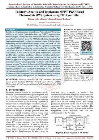
- 1. International Journal of Trend in Scientific Research and Development (IJTSRD) Volume 6 Issue 6, September-October 2022 Available Online: www.ijtsrd.com e-ISSN: 2456 – 6470 @ IJTSRD | Unique Paper ID – IJTSRD51828 | Volume – 6 | Issue – 6 | September-October 2022 Page 57 To Study, Analyse and Implement MPPT-P&O Based Photovoltaic (PV) System using PID Controller Raghavendera Kumar1 , Pramod Kumar Rathore2 1 Student, 2 Assistant Professor, 1,2 RKDF College of Engineering, Bhopal, Madhya Pradesh, India ABSTRACT In order to extract maximum power from a Photovoltaic (PV) screen, a different Maximum Power Point Tracking (MPPT) algorithm has been developed, among which the Perturb and Observe (P&O) MPPT algorithm is commonly used. The P&O algorithm may be done either by direct duty ratio or by voltage comparison power. Both have time monitoring and oscillation disadvantages across the MPP. In this case, the reference voltage produced by the algorithm is fed to the controller (PI/PID) to produce the corresponding duty ratio. The PID controller gains are determined under the normal test conditions (STC) (1000 W/m2, 25°C) of the PV panel and the same values are used for other operating conditions which do not offer satisfactory results under different operating conditions. In this article, an adaptive approach is suggested for the measurement of gains for controllers under varying operating conditions without the use of external sensors. The suggested approach defines a linear association between the PID gains measured for the STC and those for other operating conditions, and this relationship adapts the PID gains for various operating conditions. The models and experimental findings demonstrate that the suggested adaptive system specificallymeasures the maximum power and optimizes the disruption characteristics. KEYWORDS: Adaptive controller, DC–DC converter, Maximum power point tracking (MPPT), Perturb and observe (P&O), Photovoltaic (PV), Proportional integral differential controller (PID controller) How to cite this paper: Raghavendera Kumar | Pramod Kumar Rathore "To Study, Analyse and Implement MPPT- P&O Based Photovoltaic (PV) System using PID Controller" Published in International Journal of Trend in Scientific Research and Development (ijtsrd), ISSN: 2456-6470, Volume-6 | Issue-6, October 2022, pp.57-60, URL: www.ijtsrd.com/papers/ijtsrd51828.pdf Copyright © 2022 by author(s) and International Journal of Trend in Scientific Research and Development Journal. This is an Open Access article distributed under the terms of the Creative Commons Attribution License (CC BY 4.0) (http://creativecommons.org/licenses/by/4.0) 1. INTRODUCTION Increasing energy demand to population growth, industrial expansion and technologydevelopment, has led to exploring alternative energy sources for energy generation. Environmental issues with the concerns on greenhouse effects, global warming, depletion of natural reserves like natural gas, fossil fuels, coal, etc. is motivating research to invest in technology that can generate energy from renewable energy sources. Renewable energy is energy generate from the renewable natural resources, such as wind, solar radiation, rainfall tides, geothermal heat etc. The PV solar energy is direct way to convert, solar radiation into electricity and is based on the Photovoltaic effect. PV system technology has the following advantages 1) No pollution , it does not produce carbon dioxide, 2)No mechanical moving parts, no noise, direct conversion of solar radiation into electricity and Disadvantages 1) solar energy is somewhat more expensive to produce than conventional sources of energy due in part to the cost of manufacturing PV cell devices and in part to the conversion efficiencies of the equipment 2) solar power is a variable energy source, with energy production dependent on the sun. A solar PV cell generates DC current from the sunlight. The output current of a solar array depends on the ambient temperature, solar insolation, the size and configuration of the PV array. Figure.1. Block Diagram of PV Model IJTSRD51828
- 2. International Journal of Trend in Scientific Research and Development @ www.ijtsrd.com eISSN: 2456-6470 @ IJTSRD | Unique Paper ID – IJTSRD51828 | Volume – 6 | Issue – 6 | September-October 2022 Page 58 1.1. PV modules modeling A photovoltaic PV cell can be represented by an equivalent circuit, shown in Fig.1.The PV cell characteristics can be obtained by using standard equations. For simulation an entire PV system array the model of a photovoltaic PV module is developed first. Each PV system module considered in this paper. The PV cells connected in series are providing an open circuit voltage (Voc) and a short circuit current (Isc). Diode PV cell is shown in Figure.2 Equation-4 shows output current-voltage characteristic of a ideal PV cell in a single diode model. Figure.2. Solar cell equivalent circuit The equation is solved by designing a program in MATLAB, taking into account the number of solar cells which has the photovoltaic panel. The diode voltage is Vg equal to 1.2 V for crystalline silicon < 1.7 V for amorphous silicon. Where b= Vg*q/ (A*k) PV system is giving the output Voltage & Current that will be vary with the change in solar temperature and sun Irradiation. Hence to get constant voltage at the load duty cycle of the DC-DC converter should change with change in PV system voltage. In order to get constant voltage at the load MPPT Controller are design that can control the duty cycle of DC-DC converter.1.2. 1.2. Boost (DC/DC) Converter The boost converter is also known as the step-up converter. It can be used in the cases where the output voltage more than the input voltage, essentially the functioning like is versed buck converter. The practical applications which use a boost type converter appear in grid systems. µ =V0 /Vi = T/Toff = 1/1-D 1.2 Where Toff is the duration that the switch is not active, D is a duty ratio, T is the time period. Figure.3. Boost converter There are two separate ways of service where the booster converter operates. The converter is focused on the switch being closed and opened. The first mode when the switch is closed known as charging mode, second mode when the switch is opened known as discharging mode. 2. MPPT Algorithms The MPPT (maximum Power point) is a greater frequency DC/DC converters. Theytake the DC input from solar panels change to higher frequency AC & convert it back down to different DC current & voltage to exactly matched to system of the batteries. MPPT' operating at higher audio frequencies usually in 30- 80 KHz range. The benefit of higher frequency circuits is that we can be constructed with higher performance and small components. The traditional controller is charging the discharge battery, simply connecting the modules directly to the battery. This forces the modules system to operate at battery voltage, typically is not the ideal. The main principle of incremental conductance method is that the derivative of the output power (P), in terms of voltage (V), at the peak power points equal to zero (dP/dV = 0). Therefore, from the equation P=I.V, the following equation is obtained; 2.1 at the MPPT, the opposite of the instantaneous conductance of PV array system on the left side of the equation equals to the incremental conductance on the right hand side. Thus, the derivative of the points should be greater than zero on the left of the MPP while, less than zero on the right side:
- 3. International Journal of Trend in Scientific Research and Development @ www.ijtsrd.com eISSN: 2456-6470 @ IJTSRD | Unique Paper ID – IJTSRD51828 | Volume – 6 | Issue – 6 | September-October 2022 Page 59 3. PID controller A PID (proportional-integral-derivative) controller is a control loop feedback mechanism. Feedback mechanism mainly used in industrial control systems. The PID controller attempts to correct the error between a desired setpoint & a measured process variable by calculating & then output of a corrective action that can adjust the process according. As the PID controller involves calculation three different (separate) parameters, Proportional(P), Derivative(D) and the Integral (I) values. The Proportional (P) value is determine the reaction to current error, the Derivative (D) value is determine reaction based on the rate at which the error has been changed and the Integral (I) value determines the reaction based on the sum of the recent errors. To add these three actions are used to adjusting the process via a control elements. We are using PID controller to improve the performance of the voltage and peak power. PID controller gain changes the value of the output will change but after a fixed gain the value cannot be changed. 4. RESULTS The PV device increases the value of peak power, current and peak voltage by regulating the gain of the PID controller. Results are showing to the difference in between existing design and proposed design. For the improved performance the PID controller is using. Fig 4. System Representation in MATLAB (a) (b) (c) (d) (e) Fig 5-(a)-(e) figures shows various waveforms for current voltage and power from different sections. 5. Conclusion The PV cell produces DC current from the sunlight. The solar array is created by linking the individual solar cell device together. The output current of the solar array depends on the atmospheric temperature,
- 4. International Journal of Trend in Scientific Research and Development @ www.ijtsrd.com eISSN: 2456-6470 @ IJTSRD | Unique Paper ID – IJTSRD51828 | Volume – 6 | Issue – 6 | September-October 2022 Page 60 the solar insolation, the scale and layout of the PV array. In general, wider area PV panels can generate more energy and narrower PV panels will produce fewer energy. From the simulation result, the PID controller demonstrated improved results than other MPPT techniques. In the document, we use the PID controller to boost output power efficiency. If we do not add the PID controller, the output power would be 66.45 W. It gets enhanced when the PID controller is added and the output power is 79.24 W. In order to further improve the efficiency of the PV system, the Neural network may be used to further improve the performance of the output capacity. After implementing the neural network controller, the effects of the current, voltages and electricity are increased. REFERENCES [1] Zhu Y, Shi X, Dan Y, Li P, Liu W, Wei D, et Application of PSO algorithm in global MPPT for PV array. CSEE 2012; 32: 42-8. 64 [2] Mellit A, Rezzouk H, Messai A, Medjahed B. FPGA-based real time implementation of MPPT-controller for photovoltaic systems. 2011; 36: 1652-61. [3] M. Miyatake, M. Veerachary, F. Toriumi, N. Fujii and H. Ko, "Maximum Power Point Tracking of Multiple Photovoltaic Arrays: A PSO Approach,” Aerospace and Electronic Systems, IEEE Transactions on, vol. 47, pp. 367, january, 2011. [4] N. Fermia, D. Granozio, G. Petrone and M. Vitelli, "Predictive Adaptive MPPT Perturb and Observe Method,” Aerospace and Electronic Systems, IEEE Transactions on, vol. 43, pp. 934, july, 2007. [5] LK Dwivedi, P. Yadav, Dr. R. K. Saket “MATLAB based modelling and maximum power point tracking (MPPT) method for photovoltaic system under partial shading conditions ’’ IRJET vol. 3, iss. 7, 2016 [6] D. F. Dunster, Semiconductors for Engineers. Business Books,. [7] World Energy Council., "Renewable energy resources A guide to the future,” Kogan Page, [8] N. Femia, G. Petrone, G. Spagnuolo and M. Vitelli, "Optimization of perturb and observe maximum power point tracking method,” Power Electronics, IEEE Transactions on, vol. 20, pp. 963, july, 2005. [9] Jun Qi, Youbing Zhang*, Yi Chen College of Information Engineering, Zhejiang University of Technology, Hangzhou 310023, China, Renewable Energy 66 (2014) 337-345 [10] Kakosimos PE, Kladas AG. Implementation of photovoltaic array MPPT through fixed step predictive control technique. Renew Energy 2011; 36: 2508-14. [11] Patel H, Agarwal V. Maximum power point tracking scheme for PV systems operating under partially shaded conditions. IEEE Trans Ind Electron 2008; 55: 1689-98. [12] Ji Y-H, Jung D-Y, Kim J-G, Kim J-H, Lee T- W, Won C-Y. A real maximum power point tracking method for mismatching compensation in PV array under partially shaded conditions. IEEE Trans Power Electron 2011; 26: 1001-9. [13] LK Dwivedi, V. singh, A. Pareek, P. Yadav “MATLAB/ SIMULINK based study of series- parallel connected photovoltaic system under partial shaded condition ’’ IRJET vol. 3, iss. 10, 2016 [14] R. Ramaprabha and B. L. Mathur, "Characteristics of solar PV array under partial shaded conditions,” in TENCON 2008 - 2008 IEEE Region 10 Conference, 2008.