
Recommended
Recommended
More Related Content
Similar to Simulation Model for 3 Phase, 3 Wire Grid Connected System using Hybrid PV Wind Energy Conversion
Similar to Simulation Model for 3 Phase, 3 Wire Grid Connected System using Hybrid PV Wind Energy Conversion (20)
More from ijtsrd
More from ijtsrd (20)
Recently uploaded
Recently uploaded (20)
Simulation Model for 3 Phase, 3 Wire Grid Connected System using Hybrid PV Wind Energy Conversion
- 1. International Journal of Trend in Scientific Research and Development (IJTSRD) Volume 7 Issue 1, January-February 2023 Available Online: www.ijtsrd.com e-ISSN: 2456 – 6470 @ IJTSRD | Unique Paper ID – IJTSRD52630 | Volume – 7 | Issue – 1 | January-February 2023 Page 53 Simulation Model for 3-Phase, 3-Wire Grid Connected System using Hybrid PV-Wind Energy Conversion Kishan Tiwari1 , Manish Kethoriya2 1 Student, School of Research and Technology, People’s University, Bhopal, Madhya Pradesh, India 2 Assistant Professor, School of Research and Technology, People’s University, Bhopal, Madhya Pradesh, India ABSTRACT Due to rising energy demand and diminishing fossil fuel supplies, the quest for renewable energy sources has gained momentum. As a result, researchers have been more interested in harnessing renewable energy sources like sun and wind to create long-term, reliable sources of energy. The purpose of this article is to discuss long-term solutions for supplying electricity to outlying locations. The framework of a hybrid system is presented in this study. The suggested setup is a hybrid of solar photovoltaics (PV) and a wind turbine using a Doubly Fed Induction Generator (DFIG). The Maximum Power Point Tracking (MPPT) technology is used in solar panels to increase output. There are two controllers on the DFIG: one for the rotors and one for the grid. The inverter AC-DC-AC is implemented using the vector control approach, and both the rotor side converter and the grid side converter may generate or observe reactive power, as well as regulate the DC-link voltage. This study uses MATLAB Simulink to describe a PV wind system that is linked to an existing power infrastructure. This paper explains how to simulate a PV/wind hybrid system on three-phase power networks. An explanation of the simulation findings for a range of irradiance and wind speeds is provided as well. KEYWORDS: Solar PV, MPPT, Hybrid System, DFIG, Three Phase Grid, AC Load How to cite this paper: Kishan Tiwari | Manish Kethoriya "Simulation Model for 3-Phase, 3-Wire Grid Connected System using Hybrid PV-Wind Energy Conversion" Published in International Journal of Trend in Scientific Research and Development (ijtsrd), ISSN: 2456- 6470, Volume-7 | Issue-1, February 2023, pp.53-70, URL: www.ijtsrd.com/papers/ijtsrd52630.pdf Copyright © 2023 by author (s) and International Journal of Trend in Scientific Research and Development Journal. This is an Open Access article distributed under the terms of the Creative Commons Attribution License (CC BY 4.0) (http://creativecommons.org/licenses/by/4.0) 1. INTRODUCTION Over the last decade, it became apparent that the world’s resources of fossil fuels are beginning to come to an end. Estimates of energy resources vary but oil and gas reserves are thought to come to an end in roughly 40 and 60 years respectivelyand coal reserves could only be able to last another 200 years. The rapid depletion of fossil fuel resources on a worldwide basis has necessitated an urgent search for alternative energy sources to cater to the present days’ demand. Another key reason to reduce our reliance on fossil fuels is the growing evidence of the global warming phenomena. Since the industrial revolution, by burning these fossil fuels, we have caused a dramatic increase in the release of carbon dioxide into the atmosphere. The carbon dioxide accumulates in the atmosphere and absorbs the long-wave, infrared radiation emitted by the planet that will otherwise be released into space. By holding this radiation in the Earth's atmosphere, the temperature of the Earth has increased. This global warming effect would have far- reaching effects if it is not reduced as quickly as possible. The natural equilibrium of the planet is very fragile and an increase in temperature of 1 ° C to 2 ° C will break the ice caps that cause extensive floods throughout the world. It is therefore necessary to find alternative sources of energy to offset the continuously rising electricity consumption while minimising harmful environmental impacts. Alternative energy options, such as solar, wind, biomass, ocean, thermal and tidal, have drawn large- scale power generation industries. Thus, owing to their availability and incentives in local power generations, solar and wind power systems are seen as attractive forms of power generation. 1.1. Photovoltaic (PV) Power System PV power system converts sunlight into electricity. The basic unit of a photovoltaic power system is the PV cell, where cells may be grouped to form panels or modules. The panels then can be grouped to form IJTSRD52630
- 2. International Journal of Trend in Scientific Research and Development @ www.ijtsrd.com eISSN: 2456-6470 @ IJTSRD | Unique Paper ID – IJTSRD52630 | Volume – 7 | Issue – 1 | January-February 2023 Page 54 large photovoltaic array that connected in series or parallel, as shown in Fig.1. Panels connected in parallel increase the current and connected in series provide a greater output voltage. Fig. 1: Photovoltaic cell, module and array Solar cells are built of semiconductor materials capable of producing electrical current when exposed to sunlight. When a photon (light particle) strikes a photovoltaic cell, the semiconductor material captures some of the energy it carries. The energy shakes the electron loose,allowingittomovefreely. Electricalfields generatedbetweenthe positive layer (P-type) and the negative layer (N-type) of the cells then cause the loose electrons to travel in a certain direction through the connecting wire as direct current (DC) electricity. The whole method of conversion is shown in Fig. 2. Fig. 2: Schematic Block Diagram of PV Cell Small photovoltaic systems can be designed for portable use, on a fixed structure, or permanently mounted. No matter the installation, it is desired to get the maximum amount of power from the panel with minimal cost. As with wind turbinepower systems, solarpanels use various MPPT approaches depending on the case. One specific device uses an unloaded reference photovoltaic cell from which the MPPT controller determines the optimal power levels. This additional cell makes the discovery of a particular maximal power point that is not subject to electrical noise. However, extra cells can be expensive and require a greater surface area. As a consequence, this MPPT system should be reserved for fixed installations where 10 or more panels are used to collect electricity. When photovoltaic panels or other intermittent energy source are installed, particular attention shall be given to their power output in relation to the appropriate load. They are also installed to improve the power grid, or they themselves are supplemented by secondary batteries or generators. Another installation is based on photovoltaic panels, a rechargeable battery and a non-rechargeable backup battery. 1.2. Wind Energy Conversion System (WECS) Wind turbine is an important element in a wind power system to generate electricity. It is categorizeinto different sizes according to the amount of power generated. A big wind turbine can produce up to two megawatts (MW ) of electricity. A small wind turbine generates less than 100 kW of electricity, which is ideal for use as a backup source. A very small wind turbine produces between 20 and 500 watts of electricity and is usually used for charging batteries. The wind turbine absorbs the kinetic energy of the wind in a rotor composed of two or three blades physically connected to an electrical generator and is mounted on a high tower to maximise energy capture. There are actually two types of configuration for the wind turbine, the vertical-axis configuration and the commonly common horizontal-axis configuration. As shown in Fig. 3 , a horizontal-axis wind turbine consists of the following basic components.
- 3. International Journal of Trend in Scientific Research and Development @ www.ijtsrd.com eISSN: 2456-6470 @ IJTSRD | Unique Paper ID – IJTSRD52630 | Volume – 7 | Issue – 1 | January-February 2023 Page 55 1. Tower structure 2. Rotor with three blades attached to the hub 3. Shaft with mechanical gear 4. Electrical generator 5. Yaw mechanism Fig. 3: Components of a horizontal-axis wind turbine The process of converting wind energy into electricity involves manycomponents. The most noticeableelements are the blades and hubs. They run in a horizontal axis rotor like an airliner or a helicopter propeller, except in reverse. Vertical axis turbines are used less commercially because of their inefficient land use. However, theydo not need high wind speeds to start generating electricity, so theyaremost widelyusedinsuburbanareasand atlow altitudes. The hub of either the direction of the turbine may be connected to the shaft on the gearbox or straight to the engine. The gearbox is used to adjust the input torque and angular velocity. Sizes more fitting for the engine. The generator in the wind turbine is a component that transforms rotarykinetic energy into electricity. Electricity produced maybe DC, single-phase AC or three-phase AC. Each of them has a particular application which, depending on the application, introduces various difficulties. AC generators output one or two wires with a sine- wave voltage and current. The frequency of this output varies with the speed of angular rotation of the generator. The amplitude of these waves varies with the speed of rotation and the load of the output. One of the most complicated facets of using wind turbines as a source of energy is the interfacing of that power with the power grid or with equipment built to utilise the power grid. This has been done in two ways throughout history. Next, the output power frequency was changed by mechanical means. The internal generator was programmed to spin at a constant rpm, either byalteringthe gear ratio orby changing thebladepitch. Inmore advanced systems, electronic circuits are used to convert the amplitude and frequency of the power generated. The use of power electronics decreases electrical efficiency by producing heat in electrical components, but can have asignificant degree of control overthemechanicaldevice. This control helps further energyto be collected at
- 4. International Journal of Trend in Scientific Research and Development @ www.ijtsrd.com eISSN: 2456-6470 @ IJTSRD | Unique Paper ID – IJTSRD52630 | Volume – 7 | Issue – 1 | January-February 2023 Page 56 low speeds, decreased wear on the drive train, managed shutdown of the turbine and turbine speed control to increase input from the wind to the mechanical system. Using power from a generator to charge a battery or a battery bank can be challenging. The least complex approach is to use a DC generator that transfers all power directlyto thebattery. This configuration wouldnotallowtheturbineto adjust itsspeed, because it will not be able to determine the optimum speed of the rotor under increasing wind conditions. In addition, the battery could be overcharged and permanentlydamaged. In comparison, DC generators aremuch less physicallypowerful orstable than AC generators. If a single-phase or three-phase AC generator is corrected using two or six diodes, the resulting system will be more powerful than a DC generator, but still have the same speed and overcharging limits. 1.3. HYBRID SYSTEM The dc circuit is set at a steady dc voltage in many small-scale systems and typically consists of a battery bank with energy storage, a controller to prevent the batteries from overcharging, and a load. The load maybe dc, or in an ac setup, the inverter may be used. Connecting a wind generatorto aconstantdcvoltagehasbigissuesduetothe misalignment ofthe weak impedance between the generator and the constant dc voltage (battery), which restricts the flow of power to the dc grid. In response to these issues, the researchers investigated the integration of the dc- dc converter in the dc connection. The power conditioning system manages the whole powermanagement of the hybrid system. Fig.4 describes the planned electronic power interface, consisting of a wind side dc / ac converter, PV side dc / dc converter, traditional dc capacitor and grid side inverter Fig. 4: Power electronic interface of the hybrid system The voltage shift on the dc rectifier adjusts the voltage of the generator terminal and hence provides power over the current flowing out of the generator. As the current is proportional to the torque, the dc-dc converter will control the turbine rpm. The regulation of the dc-dc converter can be accomplished by means of a predetermined relationship between the rotor speed and therectifierdcvoltageto achievetheoptimum powerpoint monitoringor by means of a predetermined relationship between the electrical frequency generator and the dc-link voltage. Using these approaches, the PV / WECS hybrid generation system can provide almost good quality electricity. However, these approaches have the downside of needing expensive batteries and the installation of dump load is not an effective way of dissipating fluctuating power. Furthermore, they cannot guarantee the certainty of load requirements at all times, particularly under bad environmental conditions, where there is no power from the PV and WECS systems. Alternative energy options, such as solar, wind, biomass and ocean thermal and tidal, have drawn large-scale power generation industries. Solar and wind powersystems are perceived to be attractive sources of energydue to their affordability and topological advantages for local power generation. However, the downside, common to wind and solar solutions, is their volatile existence and reliance on weather and climate change, and fluctuations in solar and wind energy may not be compatible with the time distribution of demand. All of these energy systems will have to be oversized to make them fully reliable, resulting in an even higher overall cost. It is
- 5. International Journal of Trend in Scientific Research and Development @ www.ijtsrd.com eISSN: 2456-6470 @ IJTSRD | Unique Paper ID – IJTSRD52630 | Volume – 7 | Issue – 1 | January-February 2023 Page 57 sensible that neither a stand-alone solar energy system nor a wind energy system can provide continuous energy supply due to seasonal and intermittent variations. Fortunately, the difficulties created bythe variable existence of these resources can be partly or entirely solved by combining the two resources into a proper mix, using the strengths of one source to overcome the weakness of the other. This is clear from the fact that, in many places, more solar radiation and less wind are possible during the summer months and, equally, more windandlesssolar radiationareavailableduringthewinter.Hybridsystemsthatintegratesolar andwindpowergenerationunitswith battery backups will minimise their individual variability and dramatically reduce energy storage needs. With compatible characteristics of solar and wind energy resources at some sites, hybrid solar-wind power generation systems provide us with a highlystable supplyof energy. As a result, hybridsolar-wind powergeneration systems are becoming more and more common for the power supply of small electrical loads at remote locations (telecommunications facilities, alpinehuts or dataloggingstationsforenvironmental criteria and remote villages / locations without grid power). The planet is facing the challenge of solving the oil crisis. The ever-increasing need for traditional energy sources and the need for a stable globe and a better existence for all living beings on this planet are moving society towards research and development of new, environmentallysound energysources. Renewable energysources, such as thephotovoltaic(PV)systemandthewind energyconversion(WEC) system, have become two promising potential energy sources, while others, such as fuel cells, are at an early stage of growth. A power generation system that incorporates two or more separate sources of energy is considered a hybrid system. Hybrid power plants have greater stability and lower generation costs than those using only one source of electricity. Wind and photovoltaic are used as primary sources of electricity. The basic control system tracks the maximum power from the wind power source without calculating the speed of the wind or engine, which is very helpful for real small wind turbines. The same regulation theory refers to the monitoring of the highest power point of the photovoltaic device without detecting the level of irradiance and the temperature. Integrating photovoltaic and wind energy sources as a storage system for massive traditional batteries or super- storage condensers, leads to a stable, non-polluting energy supply and lowers overall maintenance costs. The hybrid system shall be fitted with a maximum power point trackingcontroller,which shallmonitorthemaximum power from each source and which shall be supplied to the grid. Various MPPT methods have been considered in applications for green energy. Although the demonstration or contrast of MPPT performance with other methods is outside the reach of the current work, for its simplicity and faster tracking response, a voltage- based MPPT for PV and WEC systems has been suggested. The goal of integrating WEC and PV power generation systems is to optimise output energy and reduce output volatility. The proposed hybrid system is connected to the grid by means of an inverter. 2. LITERATURE SURVEY Modeling of a stand-alone Wind-PV Hybrid Generation System Using (MATLAB/SIMULINK), Md. Wazedur Rahman; Karthikeyan Velmurugan; Md. Sultan Mahmud; Abdullah Al Mamun; Prasanth Ravindran, Published in: 2021 International Conference on Computing, Communication, and The consumption rate of fossil fuels increases promptly with the rapid deterioration of mineral resources. The associated pollution problem has led the researcher's attention to the development of experimental and simulation-based different renewable energy models. However, hybrid renewable energy sources are more efficient, reliable, and cost-effective than single renewable energy sources. For unbound localities where typical electrifications are difficult to reach, a self- sustainable PV-wind hybrid system imparts a viable solution. Wind energy conversion systems (WECS) and solar photovoltaic (PV) systems are considered for this proposed hybridization of the energy source model. This project has been developed for a standalone PV-wind hybrid generation system by considering different environmental conditions on MATLAB/Simulink software. The design of both WECS and PV systems is based on mathematical expressions developed in MATLAB/Simulink. The wind turbine so called the heart of WECS consist of a permanent magnet synchronous generator (PMSG) and a rectifier for providing DC power to the load. The unregulated DC power output procured from a PV system, further regulated by a boost converter which is integrated with a maximum power point tracking (MPPT). WECS and solar PV subsystems are imparted energy to the same DC bus where the total energy is utilized for the common DC load. The presented unique performance analysis will help the researchers to explore the PV-wind hybrid generation system for further improvements. MPPT Algorithm Based on Fuzzy Logic and Artificial Neural Network (ANN) for a Hybrid Solar/Wind Power Generation System, Hayat Elaissaoui; Mohammed Zerouali; Abdelghani El Ougli; Belkassem Tidhaf, Published in: 2020 Fourth International Conference On Intelligent Computing in Data Sciences (ICDS) In this paper we have studied a hybrid system that combines two photovoltaic and wind energy system. For the purpose of improving the performance of this system, we have proposed a new Maximum Power point
- 6. International Journal of Trend in Scientific Research and Development @ www.ijtsrd.com eISSN: 2456-6470 @ IJTSRD | Unique Paper ID – IJTSRD52630 | Volume – 7 | Issue – 1 | January-February 2023 Page 58 tracking MPPT. The proposed algorithm is based on fuzzylogic (FL) and ANN artificial neural network. For the photovoltaic system (PV), ANN is used to estimate the maximum output voltage of the photovoltaic generator (PVG) under different environmental conditions (Temperature and Solar irradiance). The fuzzy logic is used to control the DC-DC boost converter. For the wind turbine system (WT), the ANN is employed to estimate the maximum output voltage for different wind speed values and the Fuzzy Logic Controller (FLC) is used to control the DC-DC boost converter. To verify the effectiveness of the proposed MPPT, the simulation is done under MATLAB/SIMULINK. Performance Analysis of Single MPPT Technique using RBFN for PV and Wind Hybrid System, Divyanshi Srivastava; Rahul Kumar Rai; S.K. Srivastava, Published in: 2019 2nd International Conference on Power Energy, Environment and Intelligent Control (PEEIC) The renewable energy resources are intermittent in nature and it requires a unique control technique for generate the maximum power. Hybrid Renewable energy resources are mainly consists of solar and wind system. This paper describes a single MPPT controller for hybrid solar and wind system. A single MPPT control technique is used for tracking maximum power and having high efficiency as compared with other conventional methods. The performance analysis of a grid connected hybrid system with different irradiation for PV and variable speed for wind system is designed. The hybrid renewable system is simulated and analyzed by considering a 100KW solar system and 2.2KW wind system. The Proposed Mppt controller is designed in Matlab/Simulink software. Autonomous Battery Storage Energy System Control of PV-Wind Based DC Microgrid Aquib Jahangir; Sukumar Mishra, Published in: 2018 2nd International Conference on Power, Energy and Environment: Towards Smart Technology (ICEPE) This paper describes the simulation and modelling of a DC microgrid. The developed micro grid system comprises a wind turbine, solar PV array, battery energy storage system and its control interfaced with dc loads. Interfacing of the wind turbine and solar PV array via boost converter operating at MPPT to the dc grid. A constant dc bus voltage is maintained with the help of controlled Battery Energy Storage System (BESS)which is connected via a bidirectional buck-boost converter. The system is designed and analyzed in MATLAB-SIMULINK under different operating conditions of wind speed and solar irradiation and the results have been plotted. Output Maximization by Modeling and Simulation of Hybrid Wind/Photovoltaic Standalone Generation, P Rakshith; Jahnavi R Bhat; M Ashwini; C R Rakshitha; Vinay kumar sharma, Published in: 2017 International Conference on Current Trends in Computer, Electrical, Electronics and Communication (CTCEEC) This paper illustrate the hybridsystem of both Wind energy system and Photovoltaic module, which is simulated in MATLAB/SIMULINK software. In which a SEPIC (DC/DC converter) converter is used to convert the varying DC voltage to a constant output voltage by using its control mechanism. MPPT is in charge for extracting the maximum possible output power from the photovoltaic and the wind energy system. In this paper Incremental conductance (InCond) method is used as the algorithm in our MPPT block. The simulated system proposed uses a three-level, three phases, twelve pulse inverter for converting DC voltage generated by the photovoltaic model and the wind energy system to AC voltage at desired frequency and voltage level. The usage of three-level inverter reduces Total Harmonic Distortion (THD) in output voltage. Solar PV system primarilypowers DC and AC loads with battery storage option. Lead-acid batteries are used due to their large availability in many sizes, low cost and well firm performance characteristics. The importance of developing MPPT (Maximum Power Tracking) algorithms is demonstrated by analyzing the effect of shading on the PV system efficiency. The main concentration here is to develop a system to make use of the renewable energy source (i.e., Photovoltaic and Wind power) which is available in the vicinity to provide power to the isolated loads and increases the efficiency of the system by implementing MPPT technique. 3. METHODOLOGY Spotless and sustainable power sources like photovoltaic (PV) control is played a significant job in electric power age, and become basic nowadays because of deficiency and natural effects of customary powers. The sunlight-based vitality is straightforwardly changed over into electrical vitality by sun based photovoltaic modules. As a result of nonlinear I-V and PV qualities of PV sources, their yield power is principally relied on the ecological conditions and nature of burden associated. Thus, these conditions will be influenced the general productivity of the PV frameworks [1]. But the productivity of the sun-based PV module is low. Because of the mind-boggling expense of sun-based cells, a most extreme power point tracker is expected to work the PV cluster at its greatest power point. Subsequently the greatest power is extricated from the PV generator depends on three variables: insolation, load profile (load impedance) and cell temperature (surrounding temperature). To get the most extreme power from PV, a greatest power point tracker (MPPT) is utilized [2]. There are so many
- 7. International Journal of Trend in Scientific Research and Development @ www.ijtsrd.com eISSN: 2456-6470 @ IJTSRD | Unique Paper ID – IJTSRD52630 | Volume – 7 | Issue – 1 | January-February 2023 Page 59 methods and algorithms for tracking of the MPP of the PV systems. In this paper, comparative investigations of Perturb and observe (P&O) algorithm and artificial neural network (ANN) technique algorithm using dc-dc converter is done in terms of the maximum power transfer capability of these algorithms. 3.1. SOLAR CELL AND EFFECT OF IRRADIANCE AND TEMPERATURE PHOTOVOLTAIC (PV) SYSTEM In this section, model development of a PV module is given in detail. The PV model developed for this study is based on the research work by Caisheng Wang (2006). Modelling for PV Cell/Module The most commonly used model for a PV cell is the one-diode equivalent circuit as shown in Fig.5. Since the shunt resistance Rsh is large, it normally can be neglected. The five parameters model shown in Fig.5(a) can therefore be simplified into that shown in Fig.5(b). This simplified equivalent circuit model is used in this study. Fig.5: One-diode equivalent circuit model for a PV cell. (a) Five parameters model; (b) Simplified four parameters model. 3.2. EFFECT OF VARIATION OF SOLAR IRRADIATION The P-V and I-V curves of a solar cell are highly dependent on the solar irradiation values. The solar irradiation as a result of the environmental changes keeps on fluctuating, but control mechanisms are available that can track this change and can alter the working of the solar cell to meet the required load demands. Higher is the solar irradiation, higher would be the solar input to the solar cell and hence power magnitude would increase for the same voltage value. With increase in the solar irradiation the open circuit voltage increases. This is due to the fact that, when more sunlight incidents on to the solar cell, the electrons are supplied with higher excitation energy, thereby increasing the electron mobility and thus more power is generated [7] and [10]. Figure 6: Variation of P-V curve with solar irradiation
- 8. International Journal of Trend in Scientific Research and Development @ www.ijtsrd.com eISSN: 2456-6470 @ IJTSRD | Unique Paper ID – IJTSRD52630 | Volume – 7 | Issue – 1 | January-February 2023 Page 60 Figure 7: Variation of I-V curve with solar irradiation 3.3. EFFECT OF VARIATION OF TEMPERATURE On the contrary the temperature increase around the solar cell has a negative impact on the power generation capability. Increase in temperature is accompanied by a decrease in the open circuit voltage value. Increase in temperature causes increase in the band gap of the material and thus more energyis required to cross this barrier. Thus, the efficiency of the solar cell is reduced [7] and [10]. Figure 8: Variation of P-V curve with temperature Figure 9: Variation of I-V with temperature
- 9. International Journal of Trend in Scientific Research and Development @ www.ijtsrd.com eISSN: 2456-6470 @ IJTSRD | Unique Paper ID – IJTSRD52630 | Volume – 7 | Issue – 1 | January-February 2023 Page 61 3.4. MODES OF OPERATION There are two modes of operation of a boost converter. Those are based on the closing and opening of the switch. The first mode is when the switch is closed; this is known as the charging mode of operation. The second mode is when the switch is open; this is known as the discharging mode of operation [12]. 3.4.1. Charging Mode In this mode of operation; the switch is closed and the inductor is charged by the source through the switch. The charging current is exponential in nature but for simplicity is assumed to be linearly varying [11]. The diode restricts the flow of current from the source to the load and the demand of the load is met by the discharging of the capacitor. 3.4.2. Discharging Mode In this mode of operation; the switch is open and the diode is forward biased [11]. The inductor now discharges and together with the source charges the capacitor and meets the load demands. The load current variation is very small and in many cases is assumed constant throughout the operation. WAVEFORMS Figure 10: Waveforms of boost converter 3.5. STAND -ALONE SOLAR POWER SYSTEM The solar PV system consists of a PV module, the dc/dc boost converter, the maximum power point tracking algorithm and the load. Radiation (R) is incident on the PV module. It generates a voltage (V) and current (I) which will be fed into the load [3]. The voltage power characteristic of a photovoltaic (PV) array is nonlinear and time varying because of the changes caused by the atmospheric conditions. When the solar radiation and temperature varies the output power of the PV module also changes. In order to obtain the maximum efficiency of the PV module, it must operate at the maximum point of the PV characteristic. The most extreme power point relies upon the temperature and irradiance which are non-direct in nature. The greatest power point following control framework is utilized and work viability on the non-straight varieties in the parameters, such as temperature and radiations [4]. A MPPT is used for extracting the maximum power from the solar PV module and transferring that power to the load. A dc/dc converter (boost converter) serves the purpose of transferring maximum power from the solar PV module to the load. A dc/dc converter acts as an interface between the load and the module. The dc/dc converter with maximum power point tracking algorithm and the load is shown in Fig. 11. By changing the duty cycle, the load impedance as seen by the source is varied and matched at the point of the peak power with the source so as to transfer the maximum power. Therefore, MPPT techniques are needed to maintain the PV array’s operating at its MPP [3].
- 10. International Journal of Trend in Scientific Research and Development @ www.ijtsrd.com eISSN: 2456-6470 @ IJTSRD | Unique Paper ID – IJTSRD52630 | Volume – 7 | Issue – 1 | January-February 2023 Page 62 Fig. 11: Block Diagram of PV System with MPPT 3.6. MAXIMUM POWER POINT TRACKING Most extreme Power Point Tracking (MPPT) is helpful apparatus in PV application. Sun oriented radiation and temperature are the primary factor for which the electric power provided by a photovoltaic framework. The voltage at which PV module can create greatest power is called 'most extreme power point (pinnacle control voltage). The primary rule of MPPT is in charge of separating the greatest conceivable power from the photovoltaic and feed it to the heap by means of dc-to-dc converter which steps up/ down the voltage to required size [5]. A. DC/DC Boost Converter The dc-dc converter is used to supply a regulated dc output with the given dc input. These are widely used as an interface between the photovoltaic panel and the load in photovoltaic generating systems. The load must be adjusted to match the current and voltage of the solar panel so as to deliver maximum power. The dc/dc converters are described as power electronic switching circuits. It converts one form of voltage to other. These may be applicable for conversion of different voltage levels. Fig. 12 shows the circuit diagram of dc-dc boost convertor [7]. Fig. 12: Circuit Diagram of Boost Converter The dc-dc boost converter circuit consists of Inductor (L), Diode (D), Capacitor (C), load resistor (RL), the control switch(S). These components are connected in such a way with the input voltage source (Vin) so as to step up the voltage. The output voltage of the boost converter is controlled by the duty cycle of the switch. Hence by varying the ON time of the switch, the output voltage can be varied. The relationships of input voltage, output voltage and duty cycle are as follow: (1) Where, Vin, Vo are the input and output voltage of the converter and D is the duty cycle of the control switch. 3.7. WIND ENERGY CONVERSION SYSTEM Among the renewable energy technologies for electricity production, wind energy technologyis themost mature and promising one. The usage of wind energy conversion systems (WECS) is growing worldwide. Moreover, the economic aspects of wind energy technologies are promising enough to support their use in both stand-alone and grid-connected applications. As the speed of the wind differs continuouslyin the region, the energyavailable from it varies continuously. This necessitates the need for complex models of all the systems involved, which lead to changes in the wind, to provide a clearer understanding of the overall environment. The permanent magnet synchronous generator (PMSG) is also used for the production of wind power. However, they are mainly used in grid-connected service. 3.7.1. Dynamic Model for Wind Turbine The following sections explain the modeling and the control principles of the wind turbine based on research work reviewed.
- 11. International Journal of Trend in Scientific Research and Development @ www.ijtsrd.com eISSN: 2456-6470 @ IJTSRD | Unique Paper ID – IJTSRD52630 | Volume – 7 | Issue – 1 | January-February 2023 Page 63 op Wind Turbine Characteristics: The power P wind (in watts) extracted from the wind is given as: Pwind =1/2 ρAv3 CP (λ, ϴ) Where T is the air density in kg / m3, A is the area occupied by the rotor blades in m2, v is the wind velocity in m / s. Cp is called the power coefficient of the rotor efficiency and is the function of the tip speed ratio (TSR) and the pitch angle (approximately). Full rotor performance Cp is obtained by a given TSR, which is specific to the aerodynamic nature of a particular turbine. The rotor must spin at high speed at high wind speed and at low wind speed to keep TSR stable at low wind speed. Optimal degree at all stages. Wind turbines with high tip speed ratios are chosen for service over a large range of wind speeds. Cp classes – curves with a pitch angle as a parameter obtained by calculation or computation maybe represented as a nonlinear function. Proper adaptation of the coefficients C1 – C5 will result in aclosesimulation of the particular turbine under consideration. The values for C1 – C5 used in this analysis are shown. The Cp-like characteristic curves at various pitch angles are plotted in Fig. 14. In Fig 14, from the set of curves we will observe that when the pitch angle is equal to 2 degrees, the tip speed ratio has a wide range and a maximum C p value of 0.35, which is ideal for wind turbines designed to operate over a wide range of wind speeds. With an increase in the pitch angle, the range of the TSR and the maximal value of the power coefficient are substantially decreased. The system chosen to transform the mechanical energy from the turbine to electrical energy was a permanent magnet synchronous generator (PMSG) which is particularly suitable for this application due to its highly beneficial characteristics such as high power density, lack of gearbox and external excitation, compact size and reduced weight. The hierarchical model of the PMSG model predicts no saturation, no sinusoidal back e.m.f. and marginal eddy current and hysteresis losses. It takes into account the iron losses and the dynamic equations for the PMSG currents are: where id, iq are the dq axes currents, vd' Vq are the dq axes voltages, Icd’ icq are the dq axes iron losses currents, imd, imq are the dq axes magnetizing currents, Ld, Lq are the dq axes inductances, If ψpm is the mutual flux due to magnets, OJ is the fundamental frequency of the stator currents, Rc is the iron losses resistance and Rst is the stator resistance. 3.7.2. MPPT FOR WECS Optimal torque control The aim of the torque controller is to optimise the efficiency of harvesting wind energy at a broad range of wind speeds, while preserving the overall defined value of the power generated by the system. It can be seen from the block diagram seen in Fig. 13 that the idea of this method is to adjust the PMSG torque at a given wind speed according to the wind turbine 's optimum reference torque. For each wind speed, a typical characteristic wind turbine with an ideal torque-speed curve plotted to intersect the Cp-max points as shown in Fig.3.14. The optimum torque of the unit ( i.e. the ideal energy capture) is calculated by the Topt Curve and the regulatory target is to keep the turbine on this curve while the wind speed varies. A torque relationship is enforced by the MPPT system on any wind speed that is able to extract maximum power. The curve Topt is defined by: Topt =Kopt * w 2 Kopt =0.5 *ρ A * (rm /λopt)3 *Cp-max Fig. 13: The block diagram of optimal torque control MPPT method
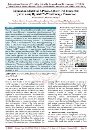
- 12. International Journal of Trend in Scientific Research and Development @ www.ijtsrd.com eISSN: 2456-6470 @ IJTSRD | Unique Paper ID – IJTSRD52630 | Volume – 7 | Issue – 1 | January-February 2023 Page 64 Fig. 14: Wind turbine characteristic for maximum power extraction 4. SIMULATION AND RESULTS This work explains grid connected PV wind system in MATLAB Simulink. simulation of a hybrid PV wind system for three phase grid system. The simulation results for varying irradiance conditions and varying wind speed conditions are also explained. Figure 15 Three Phase grid connected PV wind system
- 13. International Journal of Trend in Scientific Research and Development @ www.ijtsrd.com eISSN: 2456-6470 @ IJTSRD | Unique Paper ID – IJTSRD52630 | Volume – 7 | Issue – 1 | January-February 2023 Page 65 TABLE I: PV PARAMETERS Parameters Specifications Scale Array, Multiplier for 100 kW 0.45 Nominal Grid Connection L-L Voltage, Vrms 400 Grid Frequency, Fnom [Hz] 50 Simulation Time Step, Ts [s] 1e-6 Controller Time Step, Ts_Control 1e-4 TABLE II: WIND PARAMETERS This block implements a model of a variable speed pitch-controlled wind turbine using a doubly-fed induction generator (DFIG). Parameters Specifications Number of wind turbines 1 Nom. power, L-L volt. and freq. [Pn (VA), Vs_nom (Vrms), Vr_nom (Vrms), fn (Hz)] [45e3/.9 400 400 50] Stator [ Rs,Lls ] (p.u.) [ 0.023 0.18] Rotor [ Rr',Llr' ] (p.u.) [ 0.016 0.16] Magnetizing inductance Lm (p.u.) 2.9 Inertia constant, friction factor, and pairs of poles [ H(s) F(p.u.) p ] [0.685 0.01 3] Initial conditions [s th ias ibs ics phaseas phasebs phasecs] [ -0.2,0 0,0,0 0,0,0 ] TABLE III: THREE PHASE SOURCE (GRID) PARAMETERS Parameters Specifications Phase-to-phase voltage (Vrms) (34.5e3)*1.00243 Phase angle of phase A (degrees) 0.071468 Frequency (Hz) 50 3-phase short-circuit level at base voltage(VA) 154e6 Base voltage (Vrms ph-ph) 34.5e3 Inertia constant, friction factor, and pairs of poles [ H(s) F(p.u.) p ] [0.685 0.01 3] Initial conditions [s th ias ibs ics phaseas phasebs phasecs] [ -0.2,0 0,0,0 0,0,0 ] Figure 16. PVS GRID VOLTAGE AND CURRENT
- 14. International Journal of Trend in Scientific Research and Development @ www.ijtsrd.com eISSN: 2456-6470 @ IJTSRD | Unique Paper ID – IJTSRD52630 | Volume – 7 | Issue – 1 | January-February 2023 Page 66 Figure 17. WECS GRID SIDE – VOLTAGE AND CURRENT Figure 18. GRID – VOLTAGE AND CURRENT
- 15. International Journal of Trend in Scientific Research and Development @ www.ijtsrd.com eISSN: 2456-6470 @ IJTSRD | Unique Paper ID – IJTSRD52630 | Volume – 7 | Issue – 1 | January-February 2023 Page 67 Figure 19. GRID POWER (KW), SOLAR PV POWER (KW), DFIG POWER (KW) AND AC LOAD POWER (KW) Figure 20. LOAD 1 - VOLTAGE AND CURRENT
- 16. International Journal of Trend in Scientific Research and Development @ www.ijtsrd.com eISSN: 2456-6470 @ IJTSRD | Unique Paper ID – IJTSRD52630 | Volume – 7 | Issue – 1 | January-February 2023 Page 68 Figure 21. LOAD 2 - VOLTAGE & CURRENT 5. CONCLUSION In this study, a PV and Wind Hybrid Power System that is linked to the grid was modelled, simulated, and controlled. MATLAB/Simulink is used to model the system in a virtual setting. It has been shown that the MPPT method is the most effective in squeezing the most juice out of a PV array. A DFIG (doubly-fed induction generator) wind turbine is utilised in a Wind Energy Conversion system. Both the solar and wind power are fed into the power system. 5.1. FUTURE SCOPE: The suggested hybrid system is scalable to high- intensity non-linear loads. Both sinusoidally loading and non-sinusoidally loading systems may use this method. Different control schemes for the microgrid system may be created with the use of improved control approaches. Regulating the distributed generation (DG) power and managing it through DPFC to supply the load at the point of common coupling, and compensating for power quality issues, are both possible with the suggested technology. Direct current (DC) electricity from renewable sources is routed into a high-frequency alternating- current (AC) microgrid. In this situation, DPFC may be utilised to control power consumption and improve power quality. REFERENCES [1] Md. Wazedur Rahman; Karthikeyan Velmurugan; Md. Sultan Mahmud; Abdullah Al Mamun; Prasanth Ravindran “Modeling of a stand-alone Wind-PV Hybrid Generation System Using (MATLAB/SIMULINK)” IEEE 2021 International Conference on Computing, Communication, and Intelligent Systems (ICCCIS), 10.1109/ICCCIS51004.2021.9397194. [2] Hayat Elaissaoui; Mohammed Zerouali; Abdelghani El Ougli; Belkassem Tidhaf “MPPT Algorithm Based on Fuzzy Logic and Artificial Neural Network (ANN) for a Hybrid Solar/Wind Power Generation System” IEEE 2020 Fourth International Conference On Intelligent Computing in Data Sciences (ICDS), 10.1109/ICDS50568.2020.9268747. [3] Divyanshi Srivastava; Rahul Kumar Rai; S. K. Srivastava “Performance Analysis of Single MPPT Technique using RBFN for PV and Wind Hybrid System” IEEE 2019 2nd International Conference on Power Energy, Environment and Intelligent Control (PEEIC), 10.1109/PEEIC47157.2019.8976692. [4] Aquib Jahangir; Sukumar Mishra “Autonomous Battery Storage Energy System Control of PV- Wind Based DC Microgrid” IEEE 2018 2nd International Conference on Power, Energy and Environment: Towards Smart Technology (ICEPE), 10.1109/EPETSG.2018.8658550. [5] R. Alik and A. Jusoh, “Modified perturb and observe (p&o) with checking algorithm under various solar irradiation,” Solar Energy, vol. 148, pp. 128–139, 2017.
- 17. International Journal of Trend in Scientific Research and Development @ www.ijtsrd.com eISSN: 2456-6470 @ IJTSRD | Unique Paper ID – IJTSRD52630 | Volume – 7 | Issue – 1 | January-February 2023 Page 69 [6] O. Khan and W. Xiao, “Integration of start– stop mechanism to improve maximum power point tracking performance in steady state,” IEEE Transactions on Industrial Electronics, vol. 63, no. 10, pp. 6126–6135, 2016. [7] G. J. G. Jothi and N. Geetha, “An enhanced mppt technique for high gain dc-dc converter for photovoltaic applications,” in Circuit, Power and Computing Technologies (ICCPCT), 2016 International Conference on. IEEE, 2016, pp. 1–9. [8] G. Cipriani, V. D. Dio, F. Genduso, R. Miceli and D. L. Cascia, "A new modified Inc-Cond MPPT technique and its testing in a whole PV simulator under PSC,” in Proc. of the 2015 IEEE Applied Power Electronics Conference and Exposition (APEC), Charlotte, NC, pp. 3060- 3066. [9] S. K. Ji, H. Y. Kim, S. S. Hong, Y. W. Kim and S. K. Han, "Nonoscillation Maximum Power Point Tracking algorithm for Photovoltaic applications,” in Proc. of the 2014 Power Electronics and ECCE Asia (ICPE & ECCE), Jeju, pp. 380-385. [10] Yi-Hsun Chiu, Yu-Shan Cheng, Yi-Hua Liu, Shun-Chung Wang and ZongZhen Yang, "A novel asymmetrical FLC-based MPPT technique for photovoltaic generation system,” in Proc. of the 2014 International Power Electronics Conference (IPEC-Hiroshima 2014 - ECCE ASIA), Hiroshima, pp. 3778-3783. [11] S. Dwari, L. Arnedo, S. Oggianu and V. Blasko, "An advanced high performance maximum power point tracking technique for photovoltaic systems,” in Proc. of the 2013 IEEE Applied Power Electronics Conference and Exposition (APEC), Long Beach, CA, 2013, pp. 3011- 3015. [12] N. Mendis, K. M. Muttaqi, S. Sayeef and S. Perera, "Standalone Operation of Wind Turbine-Based Variable Speed Generators With Maximum Power Extraction Capability,” IEEE Transactions on Energy Conversion, vol. 27, no. 4, pp. 822-834, Dec. 2012. [13] S. Poshtkouhi and O. Trescases, "Multi-input single-inductor dc-dc converter for MPPT in parallel-connected photovoltaic applications,” in Proc. of the 2011 IEEE Applied Power Electronics Conference and Exposition (APEC), Fort Worth, TX, pp. 41-47. [14] I. Colak, E. Kabalci and G. Bal, "Parallel DC- AC conversion system based on separate solar farms with MPPT control,” in Proc. of the 2011 Power Electronics and ECCE Asia (ICPE & ECCE), Jeju, pp. 1469-1475. [15] G. Gamboa, J. Elmes, C. Hamilton, J. Baker, M. Pepper and I. Batarseh, "A unity power factor, maximum power point tracking battery charger for low power wind turbines,” in Proc. of the 2010 IEEE Applied Power Electronics Conference and Exposition (APEC), Palm Springs, CA, pp. 143-148. [16] M. E. Haque, M. Negnevitsky and K. M. Muttaqi,” A novel control strategy for a variable-speed wind turbine with a permanent magnet synchronous generator”. IEEE Transactions on industry application, vol. 46, no. 1, pp. 331-339, jan/feb 2010. [17] M. Kiani, D. Torregrossa, M. Simoes, F. Peyraut and A. Miraoui, "A novel maximum peak power tracking controller for wind energy systems powered by induction generators,” in Proc. of the 2009 IEEE Electrical Power & Energy Conference (EPEC), Montreal, QC, pp. 1-3. [18] M. Shirazi, A. H. Viki and O. Babayi, "A comparative study of maximum power extraction strategies in PMSG wind turbine system,” in Proc. of the 2009 IEEE Electrical Power & Energy Conference (EPEC), Montreal, QC, pp. 1-6. [19] H. Patel and V. Agarwal, "Maximum Power Point Tracking Scheme for PV Systems Operating Under Partially Shaded Conditions,” IEEE Transactions on Industrial Electronics, vol. 55, no. 4, pp. 1689-1698, April 2008. [20] M. E. Haque, K. M. Muttaqi and M. Negnevitsky, “Control of a Standalone variable speed wind turbine with a permanent magnet synchronous generator”, Proceeding of IEEE power and energy society general meeting, pp. 20-24 july 2008. [21] T. Esram and P. L. Chapman, "Comparison of Photovoltaic Array Maximum Power Point Tracking Techniques,” IEEE Transactions on Energy Conversion, vol. 22, no. 2, June 2007, pp. 439-449. [22] T. F. Chan, L. L. Lai, “permanent magnet machines for distributed generation: a review”, Proc. 2007 IEEE power engineering annul meeting, pp. 1-6. [23] M. Fatu, L. Tutelea, I. Boldea, R. Teodorescu,” Novel motion sensorless control of stand alone
- 18. International Journal of Trend in Scientific Research and Development @ www.ijtsrd.com eISSN: 2456-6470 @ IJTSRD | Unique Paper ID – IJTSRD52630 | Volume – 7 | Issue – 1 | January-February 2023 Page 70 permanent magnet synchronous generator (PMSG): harmonics and negative sequence voltage compensation under nonlinear load”, 2007 European conference on Power Electronic and Application, 2-5 Sept. 2007. [24] D. Sera, R. Teodorescu, and P. Rodriguez, “PV panel model based on datasheet values” , IEEE International Symposium on Industrial Electronics, ISIE, PP. 2392-2396, 2007. [25] H. Polinder, F. F. A van der Pijl, G. J. de Vilder, P. J. Tavner, “Comparison of direct- drive and geared generator concept for wind turbine”, IEEE Transactions on Energy Conversion, vol., 21, no. 3, pp725-733, Sept. 2006. [26] Seul Ki Kim, Eung Sang Kim, Jong Bo Ahn, “Modeling and control of a Grid connected Wind/PV Hybrid Generation System”, 2005/2006 IEEE PES Transmission and Distribution Conference and Exhibition, 21-24 May 2006, pp. 1202-1207. [27] Fernando Valencaga, Pablo F. Puleston and Pedro E. Battaiotto, “Power Control of a Solar/Wind Generation System Without Wind Measurement: A Passivity/Sliding Mode Approach”, IEEE Trans. Energy Conversion, Vol. 18, No. 4, pp. 501-507, December 2003. [28] N. Mohan, T. M. Undeland and W. P. Robbins, “Power Electronic: Converters, Application, and Design”, Wiley, 2002. [29] Francois Giraud and Zyiad M. Salameh, “Steady-State Performance of a GridConnected Rooftop Hybrid Wind-Photovoltaic Power System with Battery Storage”, IEEE Trans. Energy Conversion, Vol. 16, No. 1, pp. 1-7, March 2001. [30] RiadChedid and SaifurRahman, “Unit Sizing and Control of Hybrid Wind-Solar Power Systems”, IEEE Trans. Energy Conversion, Vol. 12, No. 1, pp. 79-85, March 1997.