
Recommended
Recommended
More Related Content
What's hot
What's hot (18)
Similar to Higher Order Low Pass FIR Filter Design using IPSO Algorithm
Similar to Higher Order Low Pass FIR Filter Design using IPSO Algorithm (20)
More from ijtsrd
More from ijtsrd (20)
Recently uploaded
Recently uploaded (20)
Higher Order Low Pass FIR Filter Design using IPSO Algorithm
- 1. International Journal of Trend in Scientific Research and Development (IJTSRD) Volume: 3 | Issue: 3 | Mar-Apr 2019 Available Online: www.ijtsrd.com e-ISSN: 2456 - 6470 @ IJTSRD | Unique Paper ID – IJTSRD22899 | Volume – 3 | Issue – 3 | Mar-Apr 2019 Page: 518 Higher Order Low Pass FIR Filter Design using IPSO Algorithm M. Santhanaraj1, Rishikesh. S. S2, Subramanian. A. N2, Vijai Sooriya. Su2 1Assistant Professor, 2Student 1,2Electronics and Communication Engineering, 1,2KPR Institute of Engineering and Technology, Coimbatore, Tamil Nadu, India How to cite this paper: M. Santhanaraj| Rishikesh. S. S | Subramanian.A.N| Vijai Sooriya. Su "Higher Order Low Pass FIR Filter Design using IPSO Algorithm" Published in International Journal of Trend in Scientific Research and Development (ijtsrd), ISSN: 2456- 6470, Volume-3 | Issue-3 , April 2019, pp.518-520, URL: http://www.ijtsrd.co m/papers/ijtsrd228 99.pdf Copyright © 2019 by author(s) and International Journal of Trend in Scientific Research and Development Journal. This is an Open Access article distributed under the terms of the Creative Commons Attribution License (CC BY 4.0) (http://creativecommons.org/licenses/ by/4.0) ABSTRACT This paper presents an optimal design of digital lowpass finiteimpulse response (FIR) filter using Improved Particle Swarm Optimization (IPSO). The design target of FIR filter is to approximate the ideal filters on the request of a given designing specifications. The traditional based optimization techniques are not efficient for digital filter design. The filter specification to be realized IPSO algorithm generates the best coefficients and try to meet the ideal frequency response. Improved Particle swarmoptimization (PSO)proposesanewequation for the velocity vector and updating the particle vectors and hence the solution quality is improved. The IPSO techniqueenhancesitssearch capabilitythatleads to a higher probability of obtaining the optimal solution. In this paper for the given problem the realization of the FIR filter has been performed. The simulation results have been performed by using the improved particle swarm optimization (IPSO) method. KEYWORDS: FIR Filter, PSO,IPSO, GA, Parks and McClellan (PM) Algorithm I. INTRODUCTION The most important part of DSP is filters which takes a digital input and gives a digital output. The most common form of signal processing used to remove the frequencies in selective part and to improve magnitude, phase or group delay of the spectrum of signal. FIR filter isattractive choices because of the ease in design and good in stability. Digital filter have wide variety of application like signal processing, control system, telecommunication, in various audio and video processing and in defense equipment etc. Digital filter are better than analog filter due to its wide range of application and better performance like small in size, reliable, gives higher accuracy. Digital filter are two types; finite impulse response (FIR) and infinite impulse response (IIR). Traditionally there are many well know method for digital filter design, such as window method, frequency sampling method, etc. The windowing method consists of window function as Butterworth, Chebyshev, Kaiser etc. for FIR filters and which further transformed to digital lowpass , high pass, band pass filters . The window method for digital filter design is fast, convenient, robust but generally suboptimal. The main objective function for the design of optimal digital filters involves accurate control of various parameters of frequency spectrum and highly non- uniform, nonlinear, non-differentiable and multimodal in nature. Chebyshev FIR digital filter design is most frequently used method for exact filter design. Most efficient method for the design of exact linear phase weighted Chebyshev. FIRdigital filter is the one based on the Remez-exchange algorithm proposed by parks and McCellellan but due to its computation complexity and high pass band ripples. Such filter has great error in filter design and need optimization. But classical optimization methods cannot optimize as such objectives function and cannot converge to the global minimum solution. Particle swarm optimization technique have been recognized for the design of optimal digital filters with superior control of parameters and the highest stop band attenuation, various heuristics and stochastic optimization method have been developed, which have proved themselves quite efficient and for the design of digital filter like GA. Differential evolution etc. Here in this paper weare exploring the benefits of design FIR filterusing a stochastic technique known as Practical swarm optimization algorithm. In many aspects PSO its self proves to be far more efficient than previously discussed techniques. The Particle swarm optimization is an evolutionary optimization technique developed by Eberhartet.al. The merits of PSO lie in its simplicity to implement as well as its convergence can control via few parameters. Numerous works has been done in order to explored flexibility of FIR filter design provided by PSO and the different alteration of PSO. IJTSRD22899
- 2. International Journal of Trend in Scientific Research and Development (IJTSRD) @ www.ijtsrd.com eISSN: 2456-6470 @ IJTSRD | Unique Paper ID - IJTSRD22899 | Volume – 3 | Issue – 3 | Mar-Apr 2019 Page: 519 II. PROBLEM STATEMENT Filter is classified as non-recursive typefilter whichmeans it requires no feedback. The lacks of feedback ensure that the impulse response will be finite in duration. The main advantages of FIR filer is its linear phasefrequencyresponse which can easily extract. That is why almost all design method described in the literature deal with filter wit this property. FIR filter structure is always stable,andcandesign to have a linear phase response. The impulse response h (n) are to be determine in the design process and the values of h(n) will be determine the type of the filter e.g. low pass, high pass, band pass and band stopetc.therearethreebroad criteria on which filter designed is based , namely the filter should provide as little distortion as possible to the signal; flat pass band; exhibit attenuation characteristics with the highest stop band possible. The advantage of the FIRfilter structure is that it can achieve linear phase frequency response. Hence all design methods are described in the literature deal with filters with this property. A digital FIR filter is characterized by, where N is the filter order which has N+1 number of filter coefficients, h(n). The coefficientsh(n) will determines the low pass filter, high pass filter, etc. The coefficientsh(n) are to be determined and N represents the order of the polynomial function. This paper presents the evenorderFIR low pass filter design with coefficients h(n). Hence, (N/2+1) number of h(n) coefficients are optimized, that are finally concatenated to find the required (N+1) number of filter coefficients. Magnitudes of Ideal filter in the pass band and stop band are one and zero. Error function is formed by the errors from the magnitude responses of the ideal filter and the designed filter. In each iteration of the evolutionary algorithm, fitness values of corresponding particle vectors are calculated and are used for updating the particle vectors with new coefficients h(n). The particle vectors obtained after some number of iterations is considered to be the optimal result or best result, obtaininganoptimalfilter.filter parameters which are responsible for the filter design are stop band normalized cut-off frequency ωs , pass band normalized cut-off frequency ωp , pass band and stop band ripples δp , δs .Parks and McClellan algorithm wereoriginally developed in which N,ωs , ωp, and the ratioδp /δs is fixed. In this paper, ImprovedParticleSwarmOptimizationalgorithm is used to obtain the magnitude filter response as close as possible to the ideal response and the particle vectorsi.e.the coefficients (h0, h1,.., hN),are optimized.IPSOalgorithmtries to minimize this error fitness J and hence optimizesthefilter performance. J involves summation of allthe absoluteerrors for the whole frequency band and thus, minimization of J gives much higher stop band attenuation and lesser stop band ripples and Transition width is also reduced. III. Particle Swarm Optimization PSO is a flexible, robust population-based stochastic search or optimization technique with implicit parallelism, which can easily handle with non-differential objective functions, unlike traditional gradient basedoptimization methods.PSO is less susceptible to getting trapped on local optima unlike GA, Simulated Annealing etc. Eberhart et al. Developed PSO concept similar to the behaviour of a swarm of birds. PSO is developed through simulation of bird flocking and fish schooling in multidimensionalspace.Birdflockingoptimizes a certain objective function. Each agent / particle vector knows its best value so far (pbest). This information corresponds to personal experiences of each vector. Moreover, each vector knows the best value so far in the group (gbest) among all pbests. Namely, each vector tries to modify its position using the following information: the distance between the current position andthe pbest, and the distance between the current position and the gbest. The first term of is the previous velocityof thevector.Thesecond and third terms are used to change the velocity of the vector. Without the second and third terms, the vector will keep on ‘‘flying’’ in the same direction until it hits the boundary. The parameter w corresponds to a kind of inertia and tries to explore new areas. Here, the vector is termed for the string of real filter coefficients, h(n), where n denotes the dimension of the vector or the number of filter coefficients (N/2+1) for even, symmetric, linear phase Nth order FIR LP or HP filter to be designed. IV. Improved Particle Swarm Optimization The position of the particle is updated through iterations. These updated positions of the particles from the probable solutions for the next iteration. This new version of PSO is called Improved Particle Swarm Optimization. V. STEPS OF IPSO (Step1) Initial Particles: Randomly generate the initial population matrix. (Step2) Update globalbest: Take the particle with the best fitness value or the minimum fitness value as the global best. (Step3)Update Personalbest: Compare the newly calculated fitnessvaluewiththeprevious one for each and every individual and select the one having the better fitness value as the personal best. (Step4) Update velocity of the particles: Update velocity of the particles. (Step5) Update position of the Particle: update position of the particles. (Step6) Termination: If the maximum number of iterations is reached terminating condition is encountered.
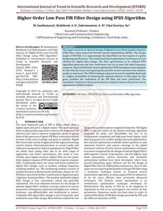
- 3. International Journal of Trend in Scientific Research and Development (IJTSRD) @ www.ijtsrd.com eISSN: 2456-6470 @ IJTSRD | Unique Paper ID - IJTSRD22899 | Volume – 3 | Issue – 3 | Mar-Apr 2019 Page: 520 Fig.1. Flowchart of IPSO VI. RESULTS AND ANALYSIS The following table the Minimum Deviation or Best Cost Function values for Improved Particle Swarm Optimization Algorithm. Here Improved Particle Swarm Optimization Algorithm (IPSO) is compared to Cuckoo Search Algorithm for better optimized results. ORDER POPULATION SIZE CSA IPSO [20] IPSO[40] 19 100 0.7 0.037245 0.00609 39 100 0.5 0.028633 0.01330 59 200 0.38 0.044178 0.00790 79 300 0.3 0.009050 0.00594 99 300 0.1 0.025994 0.01156 Fig2. CSA vs IPSO COMPARISION VII. CONCLUSION In this paper, IPSO has been used to design highr order, Low Pass FIR Filter and obtained results have been compared with some recently developed optimization algorithms like CSA and PSO. Among these two meta-heuristic algorithms like IPSO not only provides better stop-bandattenuationbut also better pass-band ripple in less computational time. Thus, we can conclude that CSA confirms efficient convergence globallywith highersuccessratesmaintaininga balance among stop-band attenuation, ripple and computational time. The future research scope includes the design of higherorderHigh-Pass,Band-Passand Band-Reject Filters using CSA.Although manyoptimizationmethodshave been discussed in this thesis for the design of digital FIR filter but there is still room to improve the design performance of the digital filter. Different new heuristic optimization methods can be explored which can reducethe complexity of the implementation of the algorithms, improves the performance of the design methods, reduces the design error and increases the convergence speed. REFERENCES [1] Stephane Coulombe and Eric Dubois, “Multidimensional windows over arbitrary lattices and their application to FIR filter design”, IEEE International Conference on Acoustics, Speech and signal Processing, 1996, vol.4 pp 2383-2386. [2] Wang Yunlong, Wang Shihu, Ji Rendong, “An Extreme Simple Method for Digital FIR Filter Design”, Third International conference on Measuring technology and Mechatronics Automation(ICMTMA),2011,vol 1,pp 410- 413. [3] T.W. Parks, J.H. McClellan, “Chebyshevapproximation for non recursive digital filters with linear phase,’ IEEE Trans. Circuits Theory, CT-19, 1972, pp. 189–194. [4] J.H. McClellan, T.W. Parks, L.R. Rabiner, “A computer program for designing optimum FIR linear phase digital filters,” IEEE Trans. Audio Electro acoust., AU-21, pp. 506–526, 1973. [5] L.R. Rabiner, “Approximate design relationships for low- pass FIR digital filters,” IEEE Trans. Audio Electroacoust., AU-21, 1973, pp. 456–460. [6] Randy L. Haupt, Sue Ellen Haupt, “Practical genetic Algorithms”, 2 nd ed., John Wiley & Sons, Inc., Publication, 2004